EP3300472B1 - Elektrisches bauteil - Google Patents
Elektrisches bauteil Download PDFInfo
- Publication number
- EP3300472B1 EP3300472B1 EP17191571.3A EP17191571A EP3300472B1 EP 3300472 B1 EP3300472 B1 EP 3300472B1 EP 17191571 A EP17191571 A EP 17191571A EP 3300472 B1 EP3300472 B1 EP 3300472B1
- Authority
- EP
- European Patent Office
- Prior art keywords
- component
- shield
- projection
- protrusion
- switching node
- Prior art date
- Legal status (The legal status is an assumption and is not a legal conclusion. Google has not performed a legal analysis and makes no representation as to the accuracy of the status listed.)
- Active
Links
Images


Classifications
-
- H—ELECTRICITY
- H05—ELECTRIC TECHNIQUES NOT OTHERWISE PROVIDED FOR
- H05K—PRINTED CIRCUITS; CASINGS OR CONSTRUCTIONAL DETAILS OF ELECTRIC APPARATUS; MANUFACTURE OF ASSEMBLAGES OF ELECTRICAL COMPONENTS
- H05K9/00—Screening of apparatus or components against electric or magnetic fields
- H05K9/0007—Casings
- H05K9/002—Casings with localised screening
- H05K9/0022—Casings with localised screening of components mounted on printed circuit boards [PCB]
-
- H—ELECTRICITY
- H10—SEMICONDUCTOR DEVICES; ELECTRIC SOLID-STATE DEVICES NOT OTHERWISE PROVIDED FOR
- H10W—GENERIC PACKAGES, INTERCONNECTIONS, CONNECTORS OR OTHER CONSTRUCTIONAL DETAILS OF DEVICES COVERED BY CLASS H10
- H10W42/00—Arrangements for protection of devices
- H10W42/20—Arrangements for protection of devices protecting against electromagnetic or particle radiation, e.g. light, X-rays, gamma-rays or electrons
Definitions
- the invention relates to an electrical component which is suitable for surface mounting and which has electromagnetic shielding.
- the object of the invention is to propose an improved component.
- the shield has a first projection protruding beyond the side surface of the electrical component.
- This has the advantage that not only the electromagnetic radiation that is emitted by the component is shielded, but also radiation that is emitted by areas that are adjacent to the component.
- the projection can protrude both over a single one of the side surfaces and over two or more of the side surfaces. In the case of a single projection, this is provided where particularly strong or particularly disruptive electromagnetic radiation is emitted. Even a small amount of radiation can be particularly disruptive if it hits components that are sensitive to interfering radiation. If there are two or more points at which such interfering radiation is emitted, a corresponding number of projections are provided for shielding this interfering radiation.
- two or four projections are provided which are arranged symmetrically.
- this has the advantage that neighboring areas of the component that are correspondingly symmetrically located are shielded.
- it facilitates the assembly of the component, since an arrangement of the component rotated by 180 ° is irrelevant due to the symmetry. Even if in this case only an area adjacent to the component If shielding is required, it is often more advantageous to use a component with two symmetrical projections, which, however, then only requires less installation effort. With a symmetrical arrangement of two projections, it is possible to dispense with ensuring the correct orientation of a single projection.
- the electrical component is, for example, a capacitor, a resistor, an inductance (coil), a transistor, an integrated circuit (IC), a diode or another electrical or electronic component.
- a component suitable for surface mounting is often referred to as an SMD (Surface Mounted Device). It generally has at least two functional connections, that is to say connections that are required for the function of the component. For a simple component such as a capacitor, resistor, inductor, or coil, there are usually two connections, for a simple transistor three, for more complex components and integrated circuits there are several. The connections are located on the underside of the component or on its side surfaces so that contact can be made on the underside.
- the underside is usually oriented towards a printed circuit board to be contacted, that is to say intended for surface mounting.
- the electromagnetic shield is, for example, a metal housing or a metallic layer surrounding the component, or some other suitable shield. It is attached in particular to the upper side of the component facing away from the printed circuit board, since this represents a large radiating surface that comes closest to adjacent components that are to be protected from electromagnetic interference.
- the ground connection of the shield connects it to a defined potential.
- the side surfaces of the component are generally perpendicular to its top or bottom and also to the circuit board on which the component is to be contacted. However, an inclined arrangement, curved side surfaces or the like are also possible here.
- the projection is advantageously arranged in a first area which is opposite a first of the functional connections. It is located on the same side surface on which this functional connection is located or which is adjacent to it. This has the advantage that the electromagnetic radiation emanating from the functional connection is shielded. This is particularly advantageous when the functional connection is not or not exclusively arranged on the underside of the component, but also extends at least partially on one of the side surfaces.
- the projection of the shield also shields the area adjacent to the functional connection, and thus additionally reduces the electromagnetic radiation and thus the influence on adjacent components. In the case of a one-sided projection, this is advantageously provided where there is a connection of the component which is particularly predestined to emit undesired electromagnetic radiation.
- the shield at least partially covers the side surface of the component in a second area which is not opposite to any of the functional connections. This has the advantage that shielding also takes place in this area of the side surface.
- the shield is advantageously made of sheet metal. This has the advantage that the projection is stable due to the thickness or shape of the sheet metal and does not deform or shift in position during operation even with fluctuating temperatures, external loads such as vibrations, drafts or the like. This ensures reliable shielding.
- the shielding consists of a metal layer which is applied to a carrier material at least in the area of the projection.
- a metal layer which is applied to a carrier material at least in the area of the projection.
- the projection or the entire shielding including the projection consists of a mechanically stable carrier material to which a metallic shielding layer is applied. It is within the scope of the invention to replace the shield with another suitable electromagnetic shielding material instead of metal, or to use such a material in addition.
- the component is advantageously provided to be connected to a switching node.
- the projection protrudes beyond the electromagnetic radiation-emitting parts of the switching node.
- This has the advantage of a particularly effective shielding, since alternating voltages and thus electromagnetic radiation often occur particularly at a switching node. It has been found that it is also sufficient here if the part of the switching node visible from above is protruded from the protrusion, and contact points covered by other components are not, or only partially protruded, from the protrusion. A certain shielding effect is already achieved by these components.
- the projection can also be designed to be rectangular with the width of the component and a length that corresponds to the maximum extent of the switching node.
- Other shapes can also be used sensibly depending on the application: a larger or smaller width of the projection, a larger or smaller length, a projection with a downwardly kinking edge area, with beveled corners, with a partially round shape or a stepped shape, or with other suitable ones Shape.
- the component is an inductance. Inductivities are particularly predestined by their properties, electromagnetic radiation at their switching input to emit.
- the projection according to the invention is particularly advantageous in this type of component.
- a switched-mode power supply according to the invention has a component according to the invention with a projection. Particularly in the case of switched-mode power supplies, for example due to their small size, the risk of electromagnetic radiation influencing adjacent components is particularly great.
- the shield according to the invention makes itself particularly advantageously noticeable with a projection.
- the conductor tracks of a switched-mode power supply are arranged in such a way that their parts intended for inspection purposes are not covered by the projection. These parts are, for example, test points at which it should be possible to tap from the outside for test purposes. Contact points of adjacent elements, which should be visible for quality control after assembly or also during operation, are not covered by the projection according to the invention.
- the parts that are not covered are to be designed so that they are as small as possible or emit as little disruptive radiation as possible.
- the solution according to the invention is in principle also suitable for shielding electromagnetic radiation from other wave ranges.
- This can, for example, also be disruptive thermal radiation, infrared light or visible light, should such occur, for example, in future optoelectronic components.
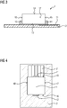
- Fig. 1 shows an electrical component 1 according to the prior art in a front view, which is suitable for surface mounting on a printed circuit board 2.
- the front functional connection 11, which is in contact with the printed circuit board 2, can be seen. It is arranged on the underside 13 of the component 1 as well as on the front side surface 15.
- the left side surface 17 and the right side surface 18 are not provided with connections.
- Fig. 2 shows the component 1 according to the prior art in side view. It can be seen that the front function connection 11 extends not only along the front side surface 15, but also a little way along the underside 13.
- the front function connection 11 adjoins a switching node 21, to which it is connected by means of the type known from the surface mounting technology of SMDs and way is contacted.
- the switching node 21 can be seen here in a sectional representation of the printed circuit board 2 and is shown schematically; in a correct side view it would not or only weakly be seen.
- the rear functional connection 12 is also contacted with a conductor track of the circuit board 2, this conductor track not being shown here.
- the rear functional connection 12 extends both over a part of the rear side surface 16 and over a part of the underside 13.
- Fig. 3 shows a component according to the prior art in side view, similar to FIG Fig. 2 .
- the front function connection 11 and the rear function connection 12 do not extend over the underside 13, but only over a part of the front side surface 15 and the rear side surface 16. They are designed to be somewhat wider than those of the Fig. 2 and are in contact with the switching node 21 or with another conductor track (not shown) on the circuit board 2.
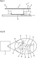
- Fig. 5 shows a component according to the invention in a front view, similar to FIG Fig. 1 .
- the electromagnetic shield 3 can be seen, which extends along the top 14, the left side surface 17 and the right side surface 18 of the component 1, as well as over parts of the underside 13.
- a left ground connection 37 and a right ground connection 38 ensure a connection of the shield 3 to ground potential or another defined potential.
- Other elements of the figure correspond to those too Fig. 1 and are not explained in more detail here.
- Fig. 6 shows a component with shielding according to the prior art in side view, similar to FIG Fig. 2 .
- the shield 3 can be seen, which extends over the top 14, but not over the rear side surface 16 or the front side surface 15.
- the right ground connection 38 which is at the rear in the figure, can be seen.
- Fig. 7 shows a component according to the invention in a side view, similar to FIG Fig. 6 .
- the shield 3 has a first projection 31 and a second projection 32.
- the projection 31 protrudes beyond the front side surface 15 so far that it covers the entire surface of the switching node 21 when viewed in a vertical projection.
- the second projection 32 is arranged symmetrically to the first projection 31 and projects far beyond the node, not shown here, at which the rear functional connection 12 is contacted. This connection is much smaller than the switching node 21 and therefore would not have required such a shield.
- the second projection 32 is designed symmetrically to the first projection 31.
- Fig. 8 shows a component according to the invention in side view, similar to that of FIG Fig. 7 .
- Only one projection 31 of the shield 3 is provided here. It is located on the front side surface 15, towering over the switching node 21.
- the shield 3 is in a region 161 of the rear side surface 16 these arranged overlapping.
- the shield 3 has a region 316 extending downward.
- Fig. 10 shows a component according to the invention in a plan view similar to FIG Fig. 9 .
- the shield 3 has both a first projection 31 and a second projection 32 which have the same width as the main part of the shield 3.
- the one here wider than in Fig. 9 designed switching node 21 is completely covered by the width of the first projection 31.
- Fig.11 shows a component according to the invention in side view.
- the shield 3 consists of a carrier material 35 which is coated with a metal layer 36.
- the coating is shown here only on the upper side of the carrier material 35; according to a variant not shown, it also extends over its lower side and optionally also along the side surfaces 15, 16, 17, 18 of the component 1.
- the metal layer 36 is connected to the ground connection 38 in connection and is connected to a defined potential via this.
- Fig.12 shows a circuit diagram detail of a switched-mode power supply 4 according to the invention, which is only indicated schematically here.
- An inductance 5 is provided as component 1 here. It is connected to a first transistor 41 and a second transistor 42, a diode 43, a capacitor 44 and a test point 45 via the switching node 21 highlighted with dots.
- the conductor track forming the switching node 21 has a large surface area which, due to the switching function of the transistors 41, 42, is predestined to emit electromagnetic radiation which is disruptive to neighboring components, in particular components neighboring the switched-mode power supply 4 influenced.
- the inductance 5 according to the invention is therefore provided with a shield with a projection, which is only symbolically indicated here in the circuit diagram with a T.
- the designation T indicates the T-shaped configuration of the shield with two projections.
- Ground connection 46, resistor 47 and the other components of the circuit diagram, not shown here, are not required for understanding the invention and are therefore not described in more detail here.
- Fig. 13 shows a section of the conductor tracks of a switched-mode power supply according to the invention.
- the conductor tracks are shown in white and the boundaries between them are shown in bold black.
- the position of the inductance 5 of the component 1, the transistors 41, 42 arranged within an integrated circuit 40, the diode 43 and a further component 48 is shown in dashed lines.
- the switching node 21 with contact surface 211 for contacting the front functional connection 11, contact surfaces 212 can be seen , 213, 214 for contacting the integrated circuit 40 and test points 215, 216.
- a contact surface 512 is provided for the rear functional connection 12 of the inductance 5, a contact surface 517 is provided for the left ground connection 37, and a contact surface 518 is provided for the right ground connection 38.
- the test point 215 is used to test the switching node 21.
- the test point 216 is also provided for this, but is somewhat further away from the main surface of the switching node 21. It is not covered by the projection 31 of the shield 3, see also
- Fig. 14 shows conductor tracks accordingly Fig. 13 , but here with the representation of the shield 3. Its circumference is shown in dash-dotted lines and its area is hatched. Except for the shield 3 all elements are identical to the previous illustration.
- the main part 33 of the shield 3 extends essentially over the inductance 5. It is followed by the projection 31 to the right. This has a more complex shape than the projections shown in the previous figures. In its upper area in the illustration, adjoining the main part 33, it has a bevel 311 which corresponds to the shape of the switching node 21 located below it.
- the projection 31 has a recess 312 so that the diode 43 is not covered and is therefore accessible for visual inspection.
- the test point 215, on the other hand, is covered by the projection 31.
- the test point 216 is not covered and is available for contact with a test device.
- the front section 313 of the projection 31 has a greater width than its area directly adjoining the main part 33.
- the relatively complex shape of the projection 31 shown here is adapted to the existing shape of the conductor tracks of the switching node 21.
- a simpler shape of the projection 31 is made possible by the fact that the shape of the switching node 21 and the adjacent conductor tracks is redesigned and, if necessary, components such as the diode 43 are arranged somewhat offset. If no optical inspection of the diode 43 or corresponding components is required, the projection 31 can project over them without any problems. Neither of these is shown here. It goes without saying that the variants presented above can also be modified and used in a different combination according to the invention.
Landscapes
- Engineering & Computer Science (AREA)
- Microelectronics & Electronic Packaging (AREA)
- Shielding Devices Or Components To Electric Or Magnetic Fields (AREA)
Description
- Die Erfindung betrifft ein elektrisches Bauteil, welches zur Oberflächenmontage geeignet ist und eine elektromagnetische Abschirmung aufweist.
- Aus der
EP 2 043 149 A1 ist ein Bauteil gemäß Oberbegriff des Anspruchs 1 bekannt. Dabei umschließt die Abschirmung das Bauteil sowohl an der Oberseite als auch an den Seitenflächen. - Aufgabe der Erfindung ist es, ein verbessertes Bauteil vorzuschlagen.
- Erfindungsgemäß ist vorgesehen, dass die Abschirmung einen über die Seitenfläche des elektrischen Bauteils hinausragenden ersten Vorsprung aufweist. Dies hat den Vorteil, dass nicht nur die elektromagnetische Strahlung abgeschirmt wird, die vom Bauteil emittiert wird, sondern auch Strahlung, die von Bereichen abgegeben wird, die dem Bauteil benachbart sind. Der Vorsprung kann dabei sowohl über eine einzige der Seitenflächen hinausragen, als auch über zwei oder mehrere der Seitenflächen. Bei einem einzigen Vorsprung ist dieser dort vorgesehen, wo besonders starke oder besonders störende elektromagnetische Strahlung emittiert wird. Auch eine geringe Strahlung kann besonders störend sein, wenn störstrahlungsempfindliche Bauteile von ihr getroffen werden. Gibt es zwei oder mehrere Stellen an denen derartige störende Strahlung emittiert wird, so werden entsprechend mehrere Vorsprünge zum Abschirmen dieser Störstrahlung vorgesehen. Vorzugsweise werden zwei oder vier Vorsprünge vorgesehen, die symmetrisch angeordnet sind. Dies hat zum einen den Vorteil, dass entsprechend symmetrisch gelegene Nachbarbereiche des Bauteils abgeschirmt werden. Zum anderen erleichtert es die Montage des Bauteils, da eine um 180° gedrehte Anordnung des Bauteils aufgrund der Symmetrie keine Rolle spielt. Auch wenn in diesem Fall nur ein dem Bauteil benachbarter Bereich einer Abschirmung bedarf, ist es oft günstiger ein Bauteil mit zwei symmetrischen Vorsprüngen zu verwenden, bei dem aber dann nur ein geringerer Montageaufwand erforderlich ist. So kann bei symmetrischer Anordnung zweier Vorsprünge auf das Sicherstellen der korrekten Orientierung eines einzigen Vorsprungs verzichtet werden.
- Das elektrische Bauteil ist beispielsweise ein Kondensator, ein Widerstand, eine Induktivität (Spule), ein Transistor, ein integrierter Schaltkreis (IC), eine Diode oder ein anderes elektrisches bzw. elektronisches Bauteil. Ein zur Oberflächenmontage geeignetes Bauteil wird oft auch als SMD (Surface Mounted Device) bezeichnet. Es weist im allgemeinen zumindest zwei Funktionsanschlüsse auf, also Anschlüsse, die zur Funktion des Bauteils benötigt werden. Bei einem einfachen Bauteil wie Kondensator, Widerstand, Induktivität, oder Spule sind es üblicherweise zwei Anschlüsse, bei einem einfachen Transistor drei, bei komplexeren Bauteilen und bei integrierten Schaltkreisen noch mehrere. Die Anschlüsse befinden sich auf der Unterseite des Bauteils oder an dessen Seitenflächen, sodass eine Kontaktierung auf der Unterseite erfolgen kann. Die Unterseite ist üblicherweise zu einer zu kontaktierenden Leiterplatte hin orientiert, also zur Oberflächenmontage vorgesehen. Die elektromagnetische Abschirmung ist beispielsweise ein Metallgehäuse oder eine das Bauteil umschließende metallische Schicht, oder eine andere geeignete Abschirmung. Sie ist insbesondere auf der der Leiterplatte abgewandten Oberseite des Bauteils angebracht, da diese eine große abstrahlende Fläche darstellt, die auch am ehesten benachbarten Bauteilen nahekommt, die vor elektromagnetischer Störstrahlung zu schützen sind. Der Masseanschluss der Abschirmung verbindet diese mit einem definierten Potential. Die Seitenflächen des Bauteils stehen im allgemeinen senkrecht zu dessen Oberseite bzw. Unterseite und auch zur Leiterplatte, auf der das Bauteil zu kontaktieren ist. Hier sind aber auch eine schräge Anordnung, gekrümmte Seitenflächen oder ähnliches möglich.
- Vorteilhafterweise ist der Vorsprung in einem ersten Bereich angeordnet, der einem ersten der Funktionsanschlüsse gegenüberliegt. Er liegt an derselben Seitenfläche, an der dieser Funktionsanschluss liegt, oder die diesem benachbart ist. Dies hat den Vorteil, dass die vom Funktionsanschluss ausgehende elektromagnetische Strahlung abgeschirmt wird. Dies ist insbesondere dann von Vorteil, wenn der Funktionsanschluss nicht oder nicht ausschließlich auf der Unterseite des Bauteils angeordnet ist, sondern sich auch zumindest teilweise auf einer der Seitenflächen hin erstreckt. Der Vorsprung der Abschirmung schirmt auch den dem Funktionsanschluss benachbarten Bereich ab, und reduziert so zusätzlich die elektromagnetische Strahlung und damit die Beeinflussung benachbarter Bauteile. Bei einem einseitigen Vorsprung ist dieser vorteilhafterweise dort vorgesehen wo sich ein Anschluss des Bauteils befindet der besonders prädestiniert ist, unerwünschte elektromagnetische Strahlung zu emittieren.
- Erfindungsgemäß ist vorgesehen, dass die Abschirmung in einem zweiten Bereich, der keinem der Funktionsanschlüsse gegenüberliegt, zumindest teilweise die Seitenfläche des Bauteils bedeckt. Dies hat den Vorteil, dass eine Abschirmung auch in diesem Bereich der Seitenfläche erfolgt.
- Vorteilhafterweise besteht die Abschirmung aus Metallblech. Dies hat den Vorteil, dass der Vorsprung durch die Dicke bzw. Formgebung des Blechs stabil ist und sich im Betrieb auch bei schwankenden Temperaturen, äußeren Belastungen wie Schwingungen, Luftzug oder ähnlichem, nicht oder nur in zulässigem Maße verformt oder in seiner Position verschiebt. Damit ist eine zuverlässige Abschirmung gewährleistet.
- Gemäß einer Variante der Erfindung besteht die Abschirmung aus einer Metallschicht, die zumindest im Bereich des Vorsprungs auf ein Trägermaterial aufgebracht ist. Dies hat den Vorteil, dass nur wenig Metall benötigt wird, aber aufgrund des Trägermaterials dennoch die erforderliche Stabilität erreicht wird. Oft reicht eine dünne Metallschicht zu Abschirmzwecken aus, weist aber nicht die erforderliche Stabilität auf, einen Vorsprung zu bilden. Daher besteht der Vorsprung oder die gesamte Abschirmung inklusive Vorsprung aus einem mechanisch stabilen Trägermaterial, auf das eine metallische Abschirmungsschicht aufgebracht ist. Es liegt im Rahmen der Erfindung, die Abschirmung statt aus Metall auch durch ein anderes geeignetes elektromagnetisch abschirmendes Material zu ersetzen, oder ein solches zusätzlich zu verwenden.
- Vorteilhafterweise ist das Bauteil dazu vorgesehen, mit einem Schaltknoten verbunden zu werden. Dabei überragt der Vorsprung die elektromagnetische Störstrahlung emittierenden Teile des Schaltknotens. Je größer der Abstand zwischen Vorsprung und Schaltknoten ist, desto größer wird der Überstand sinnvollerweise gewählt. Dies hat den Vorteil einer besonders effektiven Abschirmung, da insbesondere an einem Schaltknoten oft wechselnde Spannungen und damit elektromagnetische Abstrahlung auftritt. Es hat sich herausgestellt, dass es hier auch ausreichend ist, wenn der von oben sichtbare Teil des Schaltknotens vom Vorsprung überragt wird, und von anderen Bauteilen überdeckte Kontaktstellen nicht, oder nur teilweise vom Vorsprung überragt werden. Ein gewisser Abschirmungseffekt wird bereits durch diese Bauteile erzielt. Der Vorsprung kann aber auch der Einfachheit halber rechteckig mit der Breite des Bauteils und einer Länge die der maximalen Ausdehnung des Schaltknotens entspricht ausgelegt werden. Auch andere Formen sind je nach Anwendungsfall sinnvoll verwendbar: eine größere oder kleinere Breite des Vorsprungs, eine größere oder kleinere Länge, ein Vorsprung mit nach unten abknickendem Randbereich, mit abgeschrägten Ecken, mit einer teilweise runde Form oder einer gestuften Form, oder mit anderer geeigneter Form.
- Erfindungsgemäß ist das Bauteil eine Induktivität. Induktivitäten sind durch ihre Eigenschaften besonders prädestiniert, an ihrem Schalteingang elektromagnetische Strahlung zu emittieren. Der erfindungsgemäße Vorsprung ist bei dieser Art Bauteil besonders vorteilhaft.
- Ein Schaltnetzteil gemäß der Erfindung weist ein erfindungsgemäßes Bauteil mit Vorsprung auf. Gerade bei Schaltnetzteilen ist, beispielsweise aufgrund ihrer kleinen Bauform, die Gefahr elektromagnetischer Strahlungsbeeinflussung von benachbart angeordneten Bauelementen besonders groß. Hier macht sich die erfindungsgemäße Abschirmung mit Vorsprung besonders vorteilhaft bemerkbar.
- Erfindungsgemäß ist vorgesehen, die Leiterbahnen eines Schaltnetzteils so anzuordnen, dass ihre zu Inspektionszwecken vorgesehenen Teile nicht vom Vorsprung verdeckt werden. Diese Teile sind beispielsweise Testpunkte, an denen ein Abgriff von außen zu Testzwecken möglich sein soll. Auch Kontaktpunkte benachbarter Elemente, die zur Qualitätskontrolle nach der Montage oder auch im Betrieb sichtbar sein sollten, sind erfindungsgemäß nicht vom Vorsprung verdeckt. Dies hat den Vorteil, dass das Schaltnetzteil getestet und inspiziert werden kann, ohne auf den Vorteil der Abschirmung durch Vorsprung verzichten zu müssen. Die entsprechend nicht abgedeckten Teile sind so auszulegen, dass sie möglichst klein sind bzw. möglichst wenig störende Strahlung abgeben.
- Mit anderen Worten befasst sich die Erfindung mit dem Problem, dass Schaltknoten von Schaltnetzteilen elektromagnetische Abstrahlungen mit der Grundwelle und den Oberwellen der Regler-Schaltfrequenz verursachen. Dies führt häufig zu Grenzwertüberschreitungen bei EMV Abstrahlmessungen und erfordert oft eine komplette, kostenintensive Abschirmung des Netzteilbereiches um die geforderten Grenzwerte einhalten zu können. Dazu werden herkömmlicherweise Abschirmgehäuse über dem Netzteil verwendet. Diese sind auf der Leiterplatte anzuordnen, auf der sich das Schaltnetzteil befindet. Erfindungsgemäß wird vorgeschlagen, stattdessen ein Bauteil, hier die Induktivität, mit einer T-förmigen Abschirmung zu versehen, die den Bereich der angrenzenden Schaltung überdeckt, der elektromagnetische Störstrahlung abgibt. Diese Art der Abschirmung des Schaltknotens von Schaltreglern mittels einer in das Bauteil, hier die Induktivität, integrierten Lösung ermöglicht die Vermeidung des kostenintensiven Einsatzes von Abschirmgehäusen.
- Die erfindungsgemäße Lösung ist prinzipiell auch dazu geeignet, elektromagnetische Strahlung anderer Wellenbereiche abzuschirmen. Dies kann beispielsweise auch störende Wärmestrahlung, Infrarotlicht oder sichtbares Licht sein, sollte solches beispielsweise bei zukünftigen optoelektronischen Bauteilen störend auftreten.
- Weitere Vorteile und Ausgestaltungen der Erfindung ergeben sich auch aus der nachfolgenden Beschreibung anhand von Zeichnungen. Dabei zeigen:
- Fig.1
- Bauteil gemäß Stand der Technik in Vorderansicht
- Fig.2
- Bauteil gemäß Stand der Technik in Seitenansicht
- Fig.3
- Bauteil gemäß Stand der Technik in Seitenansicht
- Fig.4
- Bauteil gemäß Stand der Technik in Draufsicht
- Fig.5
- erfindungsgemäßes Bauteil in Vorderansicht
- Fig.6
- Bauteil gemäß Stand der Technik in Seitenansicht
- Fig.7
- erfindungsgemäßes Bauteil in Seitenansicht
- Fig.8
- erfindungsgemäßes Bauteil in Seitenansicht
- Fig.9
- erfindungsgemäßes Bauteil in Draufsicht
- Fig.10
- erfindungsgemäßes Bauteil in Draufsicht
- Fig.11
- erfindungsgemäßes Bauteil in Seitenansicht
- Fig.12
- Schaltplandetail eines erfindungsgemäßen Schaltnetzteils
- Fig.13
- Leiterbahnen eines erfindungsgemäßen Schaltnetzteils
- Fig.14
- Leiterbahnen eines erfindungsgemäßen Schaltnetzteils
-
Fig.1 zeigt ein elektrisches Bauteil 1 gemäß Stand der Technik in Vorderansicht, welches zur Oberflächenmontage auf einer Leiterplatte 2 geeignet ist. Man erkennt den vorderen Funktionsanschluss 11, der mit der Leiterplatte 2 in Kontakt steht. Er ist an der Unterseite 13 des Bauteils 1 angeordnet sowie an der vorderen Seitenfläche 15. Die linke Seitenfläche 17 und die rechte Seitenfläche 18 sind nicht mit Anschlüssen versehen. -
Fig.2 zeigt das Bauteil 1 gemäß Stand der Technik in Seitenansicht. Man erkennt, dass sich der vordere Funktionsanschluss 11 nicht nur entlang der vorderen Seitenfläche 15 erstreckt, sondern auch ein Stück weit entlang der Unterseite 13. Der vordere Funktionsanschluss 11 grenzt an einen Schaltknoten 21 an, an den er mittels aus der Oberflächenmontagetechnik von SMDs bekannten Art und Weise kontaktiert ist. Der Schaltknoten 21 ist hier in geschnittener Darstellung der Leiterplatte 2 erkennbar und schematisch dargestellt, in korrekter Seitenansicht wäre er nicht oder nur schwach erkennbar. Der hintere Funktionsanschluss 12 ist ebenfalls mit einer Leiterbahn der Leiterplatte 2 kontaktiert, wobei diese Leiterbahn hier nicht dargestellt ist. Der hintere Funktionsanschluss 12 erstreckt sich sowohl über einen Teil der hinteren Seitenfläche 16 als auch über einen Teil der Unterseite 13. -
Fig.3 zeigt ein Bauteil gemäß Stand der Technik in Seitenansicht, ähnlich zuFig.2 . Hier erstrecken sich der vordere Funktionsanschluss 11 und der hintere Funktionsanschluss 12 nicht über die Unterseite 13, sondern nur über ein Teil der vorderen Seitenfläche 15 beziehungsweise der hinteren Seitenfläche 16. Sie sind etwas breiter ausgelegt als diejenigen derFig.2 und stehen mit dem Schaltknoten 21 beziehungsweise mit einer nicht dargestellten anderen Leiterbahn der Leiterplatte 2 in Kontakt. -
Fig.4 zeigt ein Bauteil 1 gemäß Stand der Technik in Draufsicht. Man erkennt den vorderen Funktionsanschluss 11 und den hinteren Funktionsanschluss 12, die über die vordere Seitenfläche 15 beziehungsweise die hintere Seitenfläche 16 des Bauteils 1 hinausragen. Der vordere Funktionsanschluss steht in Kontakt mit dem Schaltknoten 21, der eine vergleichsweise große Ausdehnung auf der Leiterplatte 2 hat, und daher prädestiniert ist, elektromagnetische Strahlung zu emittieren. Am Schaltknoten 21 sind weitere, hier nicht dargestellte Bauteile kontaktiert, die zum Ausführen einer Schaltfunktion dienen. -
Fig.5 zeigt ein erfindungsgemäßes Bauteil in Vorderansicht, ähnlich zuFig.1 . Man erkennt die elektromagnetische Abschirmung 3, die sich entlang der Oberseite 14, der linken Seitenfläche 17 und der rechten Seitenfläche 18 des Bauteils 1 erstreckt, sowie über Teile der Unterseite 13. Ein linker Masseanschluss 37 und ein rechter Masseanschluss 38 sorgen für eine Verbindung der Abschirmung 3 zu Massepotential bzw. einem anderen definierten Potential. Andere Elemente der Abbildung entsprechen den zuFig. 1 beschriebenen und werden hier nicht näher erläutert. -
Fig.6 zeigt ein Bauteil mit Abschirmung gemäß Stand der Technik in Seitenansicht, ähnlich zuFig.2 . Man erkennt die Abschirmung 3, die sich über die Oberseite 14 erstreckt, aber nicht über die hintere Seitenfläche 16 oder die vordere Seitenfläche 15. In dieser Schnittdarstellung ist nur der rechte Masseanschluss 38, der in der Abbildung hinten liegt, erkennbar. -
Fig.7 zeigt ein erfindungsgemäßes Bauteil in Seitenansicht, ähnlich zuFig.6 . Hier weist die Abschirmung 3 einen ersten Vorsprung 31 und einen zweiten Vorsprung 32 auf. Der Vorsprung 31 ragt über die vordere Seitenfläche 15 so weit hinaus, dass er die gesamte Fläche des Schaltknotens 21 in senkrechter Projektion gesehen abdeckt. Der zweite Vorsprung 32 ist symmetrisch zum ersten Vorsprung 31 angeordnet und überragt den hier nicht dargestellten Knoten, an dem der hintere Funktionsanschluss 12 kontaktiert ist, weit. Dieser Anschluss ist wesentlich kleiner als der Schaltknoten 21 und hätte daher keine derartige Abschirmung erfordert. Aus Gründen der einfachen Montage ist aber der zweite Vorsprung 32 symmetrisch zum ersten Vorsprung 31 ausgelegt. -
Fig.8 zeigt ein erfindungsgemäßes Bauteil in Seitenansicht, ähnlich zu demjenigen derFig.7 . Hier ist nur ein Vorsprung 31 der Abschirmung 3 vorgesehen. Er befindet sich an der vorderen Seitenfläche 15, den Schaltknoten 21 überragend. An der hinteren Seitenfläche 16 ist die Abschirmung 3 in einem Bereich 161 der hinteren Seitenfläche 16 diese überdeckend angeordnet. Die Abschirmung 3 weist dazu einen sich nach unten erstreckenden Bereich 316 auf. -
Fig.9 zeigt ein erfindungsgemäßes Bauteil 1 in Draufsicht. Man erkennt die Abschirmung 3 mit Vorsprung 31, der eine geringere Breite als der Hauptteil der Abschirmung 3 aufweist. Gestrichelt dargestellt sind der Körper des Bauteils 1, der vordere Funktionsanschluss 11 und der hintere Funktionsanschluss 12 sowie der Schaltknoten 21, die von der Abschirmung verdeckt werden. Die Leiterplatte 2 ist von dieser nur teilweise verdeckt. Der Vorsprung 31 ist so dimensioniert, dass er den Schaltknoten 21 komplett überdeckt. -
Fig.10 zeigt ein erfindungsgemäßes Bauteil in Draufsicht ähnlich zuFig.9 . Hier weist die Abschirmung 3 sowohl einen ersten Vorsprung 31 als auch einen zweiten Vorsprung 32 auf, die die gleiche Breite wie der Hauptteil der Abschirmung 3 aufweisen. Der hier breiter als inFig. 9 ausgelegte Schaltknoten 21 wird von der Breite des ersten Vorsprungs 31 komplett überdeckt. -
Fig.11 zeigt ein erfindungsgemäßes Bauteil in Seitenansicht. Hier besteht die Abschirmung 3 aus einem Trägermaterial 35, welches mit einer Metallschicht 36 beschichtet ist. Die Beschichtung ist hier nur an der Oberseite des Trägermaterials 35 gezeigt, gemäß einer nicht dargestellten Variante erstreckt sie sich auch über deren Unterseite und gegebenenfalls auch entlang der Seitenflächen 15,16, 17,18 des Bauteils 1. Die Metallschicht 36 steht mit dem Masseanschluss 38 in Verbindung und ist über diesen mit definiertem Potential verbunden. -
Fig.12 zeigt ein Schaltplandetail eines erfindungsgemäßen Schaltnetzteils 4, welches hier nur schematisch angedeutet ist. Als Bauteil 1 ist hier eine Induktivität 5 vorgesehen. Sie steht über den gepunktet hervorgehobenen Schaltknoten 21 mit einem ersten Transistor 41 und einem zweiten Transistor 42, eine Diode 43, einem Kondensator 44 und einem Testpunkt 45 in Verbindung. - Aufgrund der vielen mit ihm in Verbindung stehenden Bauteile weist die den Schaltknoten 21 bildende Leiterbahn eine große Oberfläche auf, die aufgrund der Schaltfunktion der Transistoren 41,42 dazu prädestiniert ist, elektromagnetische Strahlung abzugeben, welche benachbarte Bauteile, insbesondere dem Schaltnetzteil 4 benachbarte Bauteile, störend beeinflusst. Die erfindungsgemäße Induktivität 5 ist daher mit einer Abschirmung mit Vorsprung versehen, die hier im Schaltplan nur symbolisch mit einem T angedeutet ist. Die Bezeichnung T weist auf die T-förmige Ausgestaltung der Abschirmung mit zwei Vorsprüngen hin. Masseanschluss 46, Widerstand 47 und die weiteren, hier nicht dargestellten Bauteile des Schaltplans sind zum Verständnis der Erfindung nicht erforderlich und werden daher hier nicht näher beschrieben.
-
Fig.13 zeigt einen Ausschnitt der Leiterbahnen eines erfindungsgemäßen Schaltnetzteils. Dabei sind die Leiterbahnen weiß dargestellt, die Grenzen zwischen ihnen fett schwarz. Gestrichelt dargestellt ist die Position der Induktivität 5 des Bauteils 1, der innerhalb eines integrierten Schaltkreises 40 angeordneten Transistoren 41,42, der Diode 43 und eines weiteren Bauteils 48. Man erkennt den Schaltknoten 21 mit Kontaktfläche 211 zum Kontaktieren des vorderen Funktionsanschlusses 11, Kontaktflächen 212, 213, 214 zum Kontaktieren des integrierten Schaltkreises 40 und von Testpunkten 215, 216. Für den hinteren Funktionsanschluss 12 der Induktivität 5 ist eine Kontaktfläche 512 vorgesehen, für den linken Masseanschluss 37 eine Kontaktfläche 517, und für den rechten Masseanschluss 38 eine Kontaktfläche 518. Der Testpunkt 215 dient zum Testen des Schaltknotens 21. Der Testpunkt 216 ist ebenfalls dafür vorgesehen, liegt aber etwas weiter beanstandet von der Hauptfläche des Schaltknotens 21. Er wird nicht von dem Vorsprung 31 der Abschirmung 3 überdeckt, siehe dazu auch die folgende Abbildung. -
Fig.14 zeigt Leiterbahnen entsprechendFig.13 , hier aber mit der Darstellung der Abschirmung 3. Ihr Umfang ist strichpunktiert dargestellt, ihre Fläche schraffiert. Bis auf die Abschirmung 3 sind alle Elemente mit der vorhergehenden Abbildung identisch. Der Hauptteil 33 der Abschirmung 3 erstreckt sich im wesentlichen über der Induktivität 5. An ihn schließt sich nach rechts der Vorsprung 31 an. Dieser weist eine komplexere Form auf als die zu den vorhergehenden Abbildungen gezeigten Vorsprünge. In seinem in der Darstellung oberen, an den Hauptteil 33 angrenzenden Bereich weist er eine Abschrägung 311 auf, die der darunter befindlichen Form des Schaltknotens 21 entspricht. Der Vorsprung 31 weist eine Ausnehmung 312 auf, sodass die Diode 43 nicht bedeckt, und somit einer visuellen Inspektion zugänglich ist. Der Testpunkt 215 hingegen wird vom Vorsprung 31 bedeckt. Dafür wird der Testpunkt 216 nicht bedeckt, und steht zum Kontaktieren mit einem Testgerät zur Verfügung. Der vordere Abschnitt 313 des Vorsprungs 31 weist eine größere Breite als dessen direkt an den Hauptteil 33 grenzender Bereich auf. Damit wird die in diesem Bereich liegende Form des Schaltknotens 21 soweit abgedeckt, dass eine möglichst gute Abschirmung erzielt wird und dennoch der Testpunkt 216 gut zugänglich ist. Die hier dargestellte relativ komplexe Form des Vorsprungs 31 ist der bestehenden Form der Leiterbahnen des Schaltknotens 21 angepasst. Vorteilhafterweise wird eine einfachere Form des Vorsprungs 31 dadurch möglich, dass die Form des Schaltknotens 21 und der benachbarten Leiterbahnen umgestaltet wird, und gegebenenfalls Bauteile wie die Diode 43 etwas versetzt angeordnet werden. Falls keine optische Inspektion der Diode 43 oder entsprechender Bauteile erforderlich ist, können diese problemlos vom Vorsprung 31 überragt werden. Dies ist beides hier nicht dargestellt. Es versteht sich, dass die oben dargestellten Varianten auch abgewandelt und in anderer Kombination erfindungsgemäß einsetzbar sind.
Claims (9)
- Elektrisches Bauteil welches zur Oberflächenmontage geeignet ist, mit zumindest zwei Funktionsanschlüssen (11,12) an einer Unterseite (13) des Bauteils (1), mit einer elektromagnetischen Abschirmung (3), die an einer Oberseite (14) des Bauteils (1) angeordnet und mittels zumindest einem Masseanschluss (37,38) versehen ist, und mit zumindest einer die Oberseite (14) und die Unterseite (13) verbindenden Seitenfläche (15,16,17,18), dadurch gekennzeichnet, dass die Abschirmung (3) einen über die Seitenfläche (15,16,17,18) hinausragenden ersten Vorsprung (31) aufweist.
- Bauteil gemäß Anspruch 1, wobei der Vorsprung (31) in einem ersten Bereich angeordnet ist, der einem ersten der Funktionsanschlüsse (11) gegenüberliegt.
- Bauteil nach einem der vorhergehenden Ansprüche,
dadurch gekennzeichnet, dass die Abschirmung (3) in einem zweiten Bereich, der keinem der Funktionsanschlüsse (11,12) gegenüberliegt, zumindest teilweise die Seitenfläche (15,16,17,18) bedeckt. - Bauteil nach einem der vorhergehenden Ansprüche,
dadurch gekennzeichnet, dass die Abschirmung (3) aus Metallblech besteht. - Bauteil nach einem der vorhergehenden Ansprüche,
dadurch gekennzeichnet, dass die Abschirmung (3) aus einer Metallschicht (36) besteht, die im Bereich des Vorsprungs (31,32) auf ein Trägermaterial (35) aufgebracht ist. - Bauteil nach einem der vorhergehenden Ansprüche, wobei das Bauteil (1) dazu vorgesehen ist, mit einem Schaltknoten (21) verbunden zu werden, der eine erste flächige Form aufweist, und wobei der Vorsprung (31,32) eine zweite flächige Form aufweist, die in senkrechter Projektion die erste flächige Form überragt.
- Bauteil nach einem der vorhergehenden Ansprüche,
dadurch gekennzeichnet, dass das Bauteil (1) eine Induktivität (5) ist. - Schaltnetzteil mit einem Bauteil (1) gemäß einem der vorhergehenden Ansprüche.
- Schaltnetzteil nach Anspruch 8 mit Leiterbahnen zum Verbinden des Bauteils (1,5) mit anderen Elementen (40,41,42,43,44,45,47,48), wobei die unterhalb des Vorsprungs (31,32) liegenden Leiterbahnen so angeordnet sind, dass ihre zu Inspektionszwecken vorgesehenen Teile (45,216) außerhalb des Bereichs des Vorsprungs (31,32) liegen.
Applications Claiming Priority (1)
| Application Number | Priority Date | Filing Date | Title |
|---|---|---|---|
| DE102016218266.8A DE102016218266A1 (de) | 2016-09-22 | 2016-09-22 | Elektrisches Bauteil |
Publications (3)
| Publication Number | Publication Date |
|---|---|
| EP3300472A2 EP3300472A2 (de) | 2018-03-28 |
| EP3300472A3 EP3300472A3 (de) | 2018-04-04 |
| EP3300472B1 true EP3300472B1 (de) | 2021-07-14 |
Family
ID=59901420
Family Applications (1)
| Application Number | Title | Priority Date | Filing Date |
|---|---|---|---|
| EP17191571.3A Active EP3300472B1 (de) | 2016-09-22 | 2017-09-18 | Elektrisches bauteil |
Country Status (2)
| Country | Link |
|---|---|
| EP (1) | EP3300472B1 (de) |
| DE (1) | DE102016218266A1 (de) |
Family Cites Families (2)
| Publication number | Priority date | Publication date | Assignee | Title |
|---|---|---|---|---|
| TWM318903U (en) | 2007-04-03 | 2007-09-11 | Chin-Fu Horng | Electromagnetic shielding device |
| EP2043149A1 (de) | 2007-09-27 | 2009-04-01 | Oticon A/S | Anordnung mit einem elektromagnetischen abgeschirmten SMD-Bauelement, Herstellungsverfahren und Anwendung |
-
2016
- 2016-09-22 DE DE102016218266.8A patent/DE102016218266A1/de not_active Withdrawn
-
2017
- 2017-09-18 EP EP17191571.3A patent/EP3300472B1/de active Active
Also Published As
| Publication number | Publication date |
|---|---|
| EP3300472A3 (de) | 2018-04-04 |
| EP3300472A2 (de) | 2018-03-28 |
| DE102016218266A1 (de) | 2018-03-22 |
Similar Documents
| Publication | Publication Date | Title |
|---|---|---|
| DE102010008553B4 (de) | Vorrichtung zur Abschirmung eines Elektronikmoduls | |
| EP0866422A2 (de) | Steckkarte für elektronische Geräte | |
| DE112016005793T5 (de) | Gleitende thermische Abschirmung | |
| EP0756447B1 (de) | Schaltungsanordnung für Kraftfahrzeuge | |
| DE102017112688A1 (de) | Kraftfahrzeugtürgriff mit Sendeeinrichtung und Sensoreinrichtung | |
| DE112015000298T5 (de) | Steuerung für einen Leistungswandler | |
| EP3300472B1 (de) | Elektrisches bauteil | |
| DE112018000569T5 (de) | Verbinder | |
| DE202006013058U1 (de) | Störstrom-widerstandsfähige Platinenanordnung | |
| DE102015108105A1 (de) | Abschirmungsstruktur einer elektronischen Geräteeinheit und Bedienfeldgehäuse | |
| DE102011053680A1 (de) | Schaltungsanordnung zur Verminderung von Oszillationsneigung | |
| DE102022207439B4 (de) | Elektronikmodul mit einem eine EMV-Schutzkammer bildenden Montageblech | |
| DE102011016480B3 (de) | Mehrteiliges Schirmgehäuse zur Abschirmung galvanisch voneinander getrennter elektrischer und/oder elektronischer Bauteile | |
| DE9300868U1 (de) | Einstückiges Isolierteil, insbesondere Spritzgießteil | |
| DE112018001014B4 (de) | Elektronische steuervorrichtung | |
| DE102017101399A1 (de) | Sensoranordnung | |
| DE202016106910U1 (de) | EMV-Kühlgerät | |
| EP0884938B1 (de) | Elektronische Baueinheit mit einer metallischen Abschirmung bei einem Anschlussbereich | |
| DE9404817U1 (de) | Leiterplattenanordnung | |
| EP3552468B1 (de) | Emv-kühlgerät | |
| DE102014109819B4 (de) | Abschirmgehäuse | |
| DE4302205C2 (de) | Einrichtung zum Reduzieren der Störstrahlung elektrischer Flachbaugruppen | |
| DE102023131023A1 (de) | Halbleitervorrichtung | |
| DE102020209603A1 (de) | Elektronische steuervorrichtung | |
| DE102023134138A1 (de) | Verfahren zum Sicherstellen der elektrischen Abschirmung eines Gerätegehäuses |
Legal Events
| Date | Code | Title | Description |
|---|---|---|---|
| PUAI | Public reference made under article 153(3) epc to a published international application that has entered the european phase |
Free format text: ORIGINAL CODE: 0009012 |
|
| STAA | Information on the status of an ep patent application or granted ep patent |
Free format text: STATUS: THE APPLICATION HAS BEEN PUBLISHED |
|
| PUAL | Search report despatched |
Free format text: ORIGINAL CODE: 0009013 |
|
| AK | Designated contracting states |
Kind code of ref document: A2 Designated state(s): AL AT BE BG CH CY CZ DE DK EE ES FI FR GB GR HR HU IE IS IT LI LT LU LV MC MK MT NL NO PL PT RO RS SE SI SK SM TR |
|
| AX | Request for extension of the european patent |
Extension state: BA ME |
|
| AK | Designated contracting states |
Kind code of ref document: A3 Designated state(s): AL AT BE BG CH CY CZ DE DK EE ES FI FR GB GR HR HU IE IS IT LI LT LU LV MC MK MT NL NO PL PT RO RS SE SI SK SM TR |
|
| AX | Request for extension of the european patent |
Extension state: BA ME |
|
| RIC1 | Information provided on ipc code assigned before grant |
Ipc: H01L 23/552 20060101ALI20180227BHEP Ipc: H05K 9/00 20060101AFI20180227BHEP |
|
| STAA | Information on the status of an ep patent application or granted ep patent |
Free format text: STATUS: REQUEST FOR EXAMINATION WAS MADE |
|
| 17P | Request for examination filed |
Effective date: 20181004 |
|
| RBV | Designated contracting states (corrected) |
Designated state(s): AL AT BE BG CH CY CZ DE DK EE ES FI FR GB GR HR HU IE IS IT LI LT LU LV MC MK MT NL NO PL PT RO RS SE SI SK SM TR |
|
| GRAP | Despatch of communication of intention to grant a patent |
Free format text: ORIGINAL CODE: EPIDOSNIGR1 |
|
| STAA | Information on the status of an ep patent application or granted ep patent |
Free format text: STATUS: GRANT OF PATENT IS INTENDED |
|
| INTG | Intention to grant announced |
Effective date: 20210315 |
|
| RIC1 | Information provided on ipc code assigned before grant |
Ipc: H01L 23/552 20060101ALI20210301BHEP Ipc: H05K 9/00 20060101AFI20210301BHEP |
|
| GRAS | Grant fee paid |
Free format text: ORIGINAL CODE: EPIDOSNIGR3 |
|
| GRAA | (expected) grant |
Free format text: ORIGINAL CODE: 0009210 |
|
| STAA | Information on the status of an ep patent application or granted ep patent |
Free format text: STATUS: THE PATENT HAS BEEN GRANTED |
|
| AK | Designated contracting states |
Kind code of ref document: B1 Designated state(s): AL AT BE BG CH CY CZ DE DK EE ES FI FR GB GR HR HU IE IS IT LI LT LU LV MC MK MT NL NO PL PT RO RS SE SI SK SM TR |
|
| REG | Reference to a national code |
Ref country code: GB Ref legal event code: FG4D Free format text: NOT ENGLISH |
|
| REG | Reference to a national code |
Ref country code: IE Ref legal event code: FG4D Free format text: LANGUAGE OF EP DOCUMENT: GERMAN |
|
| REG | Reference to a national code |
Ref country code: DE Ref legal event code: R096 Ref document number: 502017010887 Country of ref document: DE |
|
| REG | Reference to a national code |
Ref country code: AT Ref legal event code: REF Ref document number: 1411705 Country of ref document: AT Kind code of ref document: T Effective date: 20210815 |
|
| REG | Reference to a national code |
Ref country code: LT Ref legal event code: MG9D |
|
| REG | Reference to a national code |
Ref country code: NL Ref legal event code: MP Effective date: 20210714 |
|
| PG25 | Lapsed in a contracting state [announced via postgrant information from national office to epo] |
Ref country code: HR Free format text: LAPSE BECAUSE OF FAILURE TO SUBMIT A TRANSLATION OF THE DESCRIPTION OR TO PAY THE FEE WITHIN THE PRESCRIBED TIME-LIMIT Effective date: 20210714 Ref country code: RS Free format text: LAPSE BECAUSE OF FAILURE TO SUBMIT A TRANSLATION OF THE DESCRIPTION OR TO PAY THE FEE WITHIN THE PRESCRIBED TIME-LIMIT Effective date: 20210714 Ref country code: SE Free format text: LAPSE BECAUSE OF FAILURE TO SUBMIT A TRANSLATION OF THE DESCRIPTION OR TO PAY THE FEE WITHIN THE PRESCRIBED TIME-LIMIT Effective date: 20210714 Ref country code: LT Free format text: LAPSE BECAUSE OF FAILURE TO SUBMIT A TRANSLATION OF THE DESCRIPTION OR TO PAY THE FEE WITHIN THE PRESCRIBED TIME-LIMIT Effective date: 20210714 Ref country code: BG Free format text: LAPSE BECAUSE OF FAILURE TO SUBMIT A TRANSLATION OF THE DESCRIPTION OR TO PAY THE FEE WITHIN THE PRESCRIBED TIME-LIMIT Effective date: 20211014 Ref country code: NL Free format text: LAPSE BECAUSE OF FAILURE TO SUBMIT A TRANSLATION OF THE DESCRIPTION OR TO PAY THE FEE WITHIN THE PRESCRIBED TIME-LIMIT Effective date: 20210714 Ref country code: NO Free format text: LAPSE BECAUSE OF FAILURE TO SUBMIT A TRANSLATION OF THE DESCRIPTION OR TO PAY THE FEE WITHIN THE PRESCRIBED TIME-LIMIT Effective date: 20211014 Ref country code: PT Free format text: LAPSE BECAUSE OF FAILURE TO SUBMIT A TRANSLATION OF THE DESCRIPTION OR TO PAY THE FEE WITHIN THE PRESCRIBED TIME-LIMIT Effective date: 20211115 Ref country code: ES Free format text: LAPSE BECAUSE OF FAILURE TO SUBMIT A TRANSLATION OF THE DESCRIPTION OR TO PAY THE FEE WITHIN THE PRESCRIBED TIME-LIMIT Effective date: 20210714 Ref country code: FI Free format text: LAPSE BECAUSE OF FAILURE TO SUBMIT A TRANSLATION OF THE DESCRIPTION OR TO PAY THE FEE WITHIN THE PRESCRIBED TIME-LIMIT Effective date: 20210714 |
|
| PG25 | Lapsed in a contracting state [announced via postgrant information from national office to epo] |
Ref country code: PL Free format text: LAPSE BECAUSE OF FAILURE TO SUBMIT A TRANSLATION OF THE DESCRIPTION OR TO PAY THE FEE WITHIN THE PRESCRIBED TIME-LIMIT Effective date: 20210714 Ref country code: LV Free format text: LAPSE BECAUSE OF FAILURE TO SUBMIT A TRANSLATION OF THE DESCRIPTION OR TO PAY THE FEE WITHIN THE PRESCRIBED TIME-LIMIT Effective date: 20210714 Ref country code: GR Free format text: LAPSE BECAUSE OF FAILURE TO SUBMIT A TRANSLATION OF THE DESCRIPTION OR TO PAY THE FEE WITHIN THE PRESCRIBED TIME-LIMIT Effective date: 20211015 |
|
| REG | Reference to a national code |
Ref country code: DE Ref legal event code: R097 Ref document number: 502017010887 Country of ref document: DE |
|
| PG25 | Lapsed in a contracting state [announced via postgrant information from national office to epo] |
Ref country code: DK Free format text: LAPSE BECAUSE OF FAILURE TO SUBMIT A TRANSLATION OF THE DESCRIPTION OR TO PAY THE FEE WITHIN THE PRESCRIBED TIME-LIMIT Effective date: 20210714 |
|
| REG | Reference to a national code |
Ref country code: CH Ref legal event code: PL |
|
| PLBE | No opposition filed within time limit |
Free format text: ORIGINAL CODE: 0009261 |
|
| REG | Reference to a national code |
Ref country code: BE Ref legal event code: MM Effective date: 20210930 |
|
| STAA | Information on the status of an ep patent application or granted ep patent |
Free format text: STATUS: NO OPPOSITION FILED WITHIN TIME LIMIT |
|
| PG25 | Lapsed in a contracting state [announced via postgrant information from national office to epo] |
Ref country code: SM Free format text: LAPSE BECAUSE OF FAILURE TO SUBMIT A TRANSLATION OF THE DESCRIPTION OR TO PAY THE FEE WITHIN THE PRESCRIBED TIME-LIMIT Effective date: 20210714 Ref country code: SK Free format text: LAPSE BECAUSE OF FAILURE TO SUBMIT A TRANSLATION OF THE DESCRIPTION OR TO PAY THE FEE WITHIN THE PRESCRIBED TIME-LIMIT Effective date: 20210714 Ref country code: RO Free format text: LAPSE BECAUSE OF FAILURE TO SUBMIT A TRANSLATION OF THE DESCRIPTION OR TO PAY THE FEE WITHIN THE PRESCRIBED TIME-LIMIT Effective date: 20210714 Ref country code: MC Free format text: LAPSE BECAUSE OF FAILURE TO SUBMIT A TRANSLATION OF THE DESCRIPTION OR TO PAY THE FEE WITHIN THE PRESCRIBED TIME-LIMIT Effective date: 20210714 Ref country code: EE Free format text: LAPSE BECAUSE OF FAILURE TO SUBMIT A TRANSLATION OF THE DESCRIPTION OR TO PAY THE FEE WITHIN THE PRESCRIBED TIME-LIMIT Effective date: 20210714 Ref country code: CZ Free format text: LAPSE BECAUSE OF FAILURE TO SUBMIT A TRANSLATION OF THE DESCRIPTION OR TO PAY THE FEE WITHIN THE PRESCRIBED TIME-LIMIT Effective date: 20210714 Ref country code: AL Free format text: LAPSE BECAUSE OF FAILURE TO SUBMIT A TRANSLATION OF THE DESCRIPTION OR TO PAY THE FEE WITHIN THE PRESCRIBED TIME-LIMIT Effective date: 20210714 |
|
| 26N | No opposition filed |
Effective date: 20220419 |
|
| GBPC | Gb: european patent ceased through non-payment of renewal fee |
Effective date: 20211014 |
|
| REG | Reference to a national code |
Ref country code: DE Ref legal event code: R081 Ref document number: 502017010887 Country of ref document: DE Owner name: CONTINENTAL AUTOMOTIVE TECHNOLOGIES GMBH, DE Free format text: FORMER OWNER: CONTINENTAL AUTOMOTIVE GMBH, 30165 HANNOVER, DE Ref country code: DE Ref legal event code: R081 Ref document number: 502017010887 Country of ref document: DE Owner name: AUMOVIO GERMANY GMBH, DE Free format text: FORMER OWNER: CONTINENTAL AUTOMOTIVE GMBH, 30165 HANNOVER, DE |
|
| PG25 | Lapsed in a contracting state [announced via postgrant information from national office to epo] |
Ref country code: LU Free format text: LAPSE BECAUSE OF NON-PAYMENT OF DUE FEES Effective date: 20210918 Ref country code: IT Free format text: LAPSE BECAUSE OF FAILURE TO SUBMIT A TRANSLATION OF THE DESCRIPTION OR TO PAY THE FEE WITHIN THE PRESCRIBED TIME-LIMIT Effective date: 20210714 Ref country code: IE Free format text: LAPSE BECAUSE OF NON-PAYMENT OF DUE FEES Effective date: 20210918 Ref country code: GB Free format text: LAPSE BECAUSE OF NON-PAYMENT OF DUE FEES Effective date: 20211014 Ref country code: BE Free format text: LAPSE BECAUSE OF NON-PAYMENT OF DUE FEES Effective date: 20210930 |
|
| PG25 | Lapsed in a contracting state [announced via postgrant information from national office to epo] |
Ref country code: LI Free format text: LAPSE BECAUSE OF NON-PAYMENT OF DUE FEES Effective date: 20210930 Ref country code: CH Free format text: LAPSE BECAUSE OF NON-PAYMENT OF DUE FEES Effective date: 20210930 |
|
| PG25 | Lapsed in a contracting state [announced via postgrant information from national office to epo] |
Ref country code: HU Free format text: LAPSE BECAUSE OF FAILURE TO SUBMIT A TRANSLATION OF THE DESCRIPTION OR TO PAY THE FEE WITHIN THE PRESCRIBED TIME-LIMIT; INVALID AB INITIO Effective date: 20170918 |
|
| P01 | Opt-out of the competence of the unified patent court (upc) registered |
Effective date: 20230522 |
|
| PG25 | Lapsed in a contracting state [announced via postgrant information from national office to epo] |
Ref country code: CY Free format text: LAPSE BECAUSE OF FAILURE TO SUBMIT A TRANSLATION OF THE DESCRIPTION OR TO PAY THE FEE WITHIN THE PRESCRIBED TIME-LIMIT Effective date: 20210714 |
|
| REG | Reference to a national code |
Ref country code: AT Ref legal event code: MM01 Ref document number: 1411705 Country of ref document: AT Kind code of ref document: T Effective date: 20220918 |
|
| PG25 | Lapsed in a contracting state [announced via postgrant information from national office to epo] |
Ref country code: AT Free format text: LAPSE BECAUSE OF NON-PAYMENT OF DUE FEES Effective date: 20220918 |
|
| REG | Reference to a national code |
Ref country code: DE Ref legal event code: R081 Ref document number: 502017010887 Country of ref document: DE Owner name: CONTINENTAL AUTOMOTIVE TECHNOLOGIES GMBH, DE Free format text: FORMER OWNER: CONTINENTAL AUTOMOTIVE TECHNOLOGIES GMBH, 30165 HANNOVER, DE Ref country code: DE Ref legal event code: R081 Ref document number: 502017010887 Country of ref document: DE Owner name: AUMOVIO GERMANY GMBH, DE Free format text: FORMER OWNER: CONTINENTAL AUTOMOTIVE TECHNOLOGIES GMBH, 30165 HANNOVER, DE |
|
| PG25 | Lapsed in a contracting state [announced via postgrant information from national office to epo] |
Ref country code: MK Free format text: LAPSE BECAUSE OF FAILURE TO SUBMIT A TRANSLATION OF THE DESCRIPTION OR TO PAY THE FEE WITHIN THE PRESCRIBED TIME-LIMIT Effective date: 20210714 |
|
| PG25 | Lapsed in a contracting state [announced via postgrant information from national office to epo] |
Ref country code: MT Free format text: LAPSE BECAUSE OF FAILURE TO SUBMIT A TRANSLATION OF THE DESCRIPTION OR TO PAY THE FEE WITHIN THE PRESCRIBED TIME-LIMIT Effective date: 20210714 |
|
| PGFP | Annual fee paid to national office [announced via postgrant information from national office to epo] |
Ref country code: DE Payment date: 20250930 Year of fee payment: 9 |
|
| PGFP | Annual fee paid to national office [announced via postgrant information from national office to epo] |
Ref country code: FR Payment date: 20250922 Year of fee payment: 9 |
|
| PG25 | Lapsed in a contracting state [announced via postgrant information from national office to epo] |
Ref country code: TR Free format text: LAPSE BECAUSE OF FAILURE TO SUBMIT A TRANSLATION OF THE DESCRIPTION OR TO PAY THE FEE WITHIN THE PRESCRIBED TIME-LIMIT Effective date: 20210714 |
|
| REG | Reference to a national code |
Ref country code: DE Ref legal event code: R081 Ref document number: 502017010887 Country of ref document: DE Owner name: AUMOVIO GERMANY GMBH, DE Free format text: FORMER OWNER: CONTINENTAL AUTOMOTIVE TECHNOLOGIES GMBH, 30175 HANNOVER, DE |