EP3300528B1 - Schaltgerät mit einer vakuumröhre - Google Patents
Schaltgerät mit einer vakuumröhre Download PDFInfo
- Publication number
- EP3300528B1 EP3300528B1 EP16726057.9A EP16726057A EP3300528B1 EP 3300528 B1 EP3300528 B1 EP 3300528B1 EP 16726057 A EP16726057 A EP 16726057A EP 3300528 B1 EP3300528 B1 EP 3300528B1
- Authority
- EP
- European Patent Office
- Prior art keywords
- switching device
- closing
- opening
- contacts
- vacuum tube
- Prior art date
- Legal status (The legal status is an assumption and is not a legal conclusion. Google has not performed a legal analysis and makes no representation as to the accuracy of the status listed.)
- Active
Links
Images

Classifications
-
- H—ELECTRICITY
- H01—ELECTRIC ELEMENTS
- H01H—ELECTRIC SWITCHES; RELAYS; SELECTORS; EMERGENCY PROTECTIVE DEVICES
- H01H33/00—High-tension or heavy-current switches with arc-extinguishing or arc-preventing means
- H01H33/60—Switches wherein the means for extinguishing or preventing the arc do not include separate means for obtaining or increasing flow of arc-extinguishing fluid
- H01H33/66—Vacuum switches
- H01H33/666—Operating arrangements
-
- G—PHYSICS
- G01—MEASURING; TESTING
- G01R—MEASURING ELECTRIC VARIABLES; MEASURING MAGNETIC VARIABLES
- G01R31/00—Arrangements for testing electric properties; Arrangements for locating electric faults; Arrangements for electrical testing characterised by what is being tested not provided for elsewhere
- G01R31/327—Testing of circuit interrupters, switches or circuit-breakers
- G01R31/3271—Testing of circuit interrupters, switches or circuit-breakers of high voltage or medium voltage devices
- G01R31/3272—Apparatus, systems or circuits therefor
- G01R31/3274—Details related to measuring, e.g. sensing, displaying or computing; Measuring of variables related to the contact pieces, e.g. wear, position or resistance
-
- H—ELECTRICITY
- H01—ELECTRIC ELEMENTS
- H01H—ELECTRIC SWITCHES; RELAYS; SELECTORS; EMERGENCY PROTECTIVE DEVICES
- H01H1/00—Contacts
- H01H1/12—Contacts characterised by the manner in which co-operating contacts engage
- H01H1/14—Contacts characterised by the manner in which co-operating contacts engage by abutting
- H01H1/22—Contacts characterised by the manner in which co-operating contacts engage by abutting with rigid pivoted member carrying the moving contact
- H01H1/221—Contacts characterised by the manner in which co-operating contacts engage by abutting with rigid pivoted member carrying the moving contact and a contact pressure spring acting between the pivoted member and a supporting member
-
- H—ELECTRICITY
- H01—ELECTRIC ELEMENTS
- H01H—ELECTRIC SWITCHES; RELAYS; SELECTORS; EMERGENCY PROTECTIVE DEVICES
- H01H1/00—Contacts
- H01H1/50—Means for increasing contact pressure, preventing vibration of contacts, holding contacts together after engagement, or biasing contacts to the open position
- H01H1/54—Means for increasing contact pressure, preventing vibration of contacts, holding contacts together after engagement, or biasing contacts to the open position by magnetic force
-
- H—ELECTRICITY
- H01—ELECTRIC ELEMENTS
- H01H—ELECTRIC SWITCHES; RELAYS; SELECTORS; EMERGENCY PROTECTIVE DEVICES
- H01H47/00—Circuit arrangements not adapted to a particular application of the relay and designed to obtain desired operating characteristics or to provide energising current
- H01H47/22—Circuit arrangements not adapted to a particular application of the relay and designed to obtain desired operating characteristics or to provide energising current for supplying energising current for relay coil
-
- H—ELECTRICITY
- H01—ELECTRIC ELEMENTS
- H01H—ELECTRIC SWITCHES; RELAYS; SELECTORS; EMERGENCY PROTECTIVE DEVICES
- H01H3/00—Mechanisms for operating contacts
- H01H3/32—Driving mechanisms, i.e. for transmitting driving force to the contacts
- H01H2003/323—Driving mechanisms, i.e. for transmitting driving force to the contacts the mechanisms being adjustable
Definitions
- the invention relates to a switching device with a vacuum tube and an adjustable drive for opening and closing the contacts of the switching device.
- Switching devices for switching electrical currents may contain vacuum tubes.
- a vacuum tube for switching an electric current is disclosed.
- This vacuum tube includes a moving contact and a fixed contact, which can be separated from each other to turn off the electric current, and which are brought into contact for switching on the electric current.
- the switching characteristics of such a switching device with a vacuum tube as z.
- the switching force depends on the air pressure and thus on the altitude.
- Another aspect is the erection direction, in which the gravitation can act in the direction or opposite to the switching direction. This speeds up or slows down the circuit. Different switching forces lead to switching speeds and times deviating from the setpoint. Ideally, these differences need to be completely corrected.
- the DE 11 2011 105570 T5 describes an electromagnetic actuator for a vacuum circuit breaker which, by its electromagnetic actuation, controls the speed of contact switching of a vacuum interrupter used in the vacuum circuit breaker, the electromagnetic actuator comprising: a closing drive coil for the vacuum interrupter; and a first temperature sensor measuring a temperature in the vicinity of the closing drive coil, wherein a current passed through the closing drive coil is controlled on the basis of the temperature measured by the first temperature sensor.
- the invention is therefore based on the object to provide a switching device with a vacuum tube, which can automatically adapt to the operating location in the characteristics of the opening and closing of the switching device.
- the switching device according to the invention with a vacuum tube and an adjustable drive for opening and closing the contacts of the switching device according to claim 1 comprises a sensor for detecting physical characteristics of the operating location of the switching device, wherein the sensor is a sensor for measuring the position of the switching device, and a microcontroller , which evaluates the signal from the sensor, and adapts the adjustable drive for opening and closing the contacts dynamically to the place of operation. It is advantageous that such a switching device can be used at operating locations with highly fluctuating physical properties.
- the switching device can be used, for example, at a location with highly fluctuating pressure conditions.
- This can be, for example, an elevator of a mine shaft, in which the pressure conditions fluctuate greatly due to the change in the height.
- the switching device can also be adapted to the operating position.
- the force is adapted to the contacts the operating site by the adjustable drive for opening and closing.
- the adjustable opening and closing drive comprises a coil which serves for the electromagnetic adjustment of the switch force by the adjustable drive for opening and closing. The power of adjustable drive for opening and closing can be adjusted by controlling the coil current.
- the adjustable drive for opening and closing comprises at least one spring whose variable spring force is used to set the force on the contacts by the adjustable drive for opening and closing.
- the force of the drive for opening and closing the contacts can be adjusted by changing the length of the spring travel.
- the power of the drive for opening and closing the contacts is dynamically adjusted during operation of the switching device. It can be adjusted dynamically during operation of the switching device, the contact force to the site.
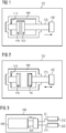
- FIG. 1 is a switching device 100 with a vacuum tube 160 and an adjustable drive 150 for opening and closing the contacts 110; 120 of the switching device 100 shown.
- the vacuum tube 160 comprises a fixed contact 110 which is mounted on a bolt 115 and a moving contact 120 which can be moved via a bolt 125. As shown in FIG. 1 are the contacts 110; 120 in the closed position, so that a current can flow.
- the switching device 100 comprises a drive 150 for opening and closing the contacts 110; 120.
- This drive 150 as shown in the FIG. 1 for opening the contacts 110; 120 move the moving contact 120 in the direction of arrow to the right.
- the adjustable drive 150 has the contacts 110; 120 separated.
- the switching device 100 is shown in more detail.
- the vacuum tube 160 includes a bellows 130 that seals the movable contact 120.
- the switching device 100 is typically set so that the force of the bellows 130 on the bolt 125 is equal to the external force due to the pressure differential between the vacuum in the vacuum tube 160 and the location of operation.
- the adjustable drive 150 for opening and closing the contacts 110; 120 includes an armature 501 which is rotatably mounted about an axis 500. According to the presentation of the FIGS. 4A and 4B are the contacts 110; 120 open, thus away from each other. By a movement of the anchor against clockwise as shown in FIG. 4A the moving contact 120 is moved toward the fixed contact 110 and thus closes the electrical current path of the switching device 100.
- the adjustable drive 150 further includes a spring 510 that causes the contacts 110; 120 are pressed against each other in the closed state with a defined force.
- the drive 150 comprises an electromagnet with a coil 530 which acts on a counterpart 531 on the armature 501 and rotates the armature counterclockwise by applying a coil current. This rotation closes the electrical contact of the switching device 100.
- the drive comprises an opening spring 520, which opens the contacts when switching off the electromagnet with coil 530. According to the position of the switching device 100, different forces act on the armature and different forces must be applied from the armature to close the switching device 100. This is for example in FIG. 4B shown, the electrical switch 100 off FIG. 4A represented rotated by 90 °.
- the switching device 100 additionally sensors 210; 220, for detecting physical characteristics of the operating location of the switching device 100. On the basis of the detected characteristics of the adjustable drive 150 for opening and closing the contacts 110; 120 adjusted the place of operation.
- the sensor 210 may be, for example, a sensor for measuring the air pressure; the sensor 220 is a sensor for measuring the position of the switching device 100.
- the sensor 210 is connected via a line 211 to the drive 150 for opening and closing the contacts 110; 120 connected.
- the adjustable drive 150 may include a microcontroller which evaluates the signal of the sensor and makes the necessary adjustments. Alternatively, this control can also be made separately from the drive 150.
- the sensor 220 is connected via the line 221 to the adjustable drive 150 for opening and closing the contacts 110; 120 connected.
- the adjustment of the adjustable drive 150 for opening and closing at the operating location is via an adjustment of the switching force on the contacts 110; 120 made.
- a coil 530 as shown in the FIGS. 4A and 4B is shown, the force on the contacts 110; 120 are made by changing the coil current.
- the electrical signals of the sensors 210; 220 which correspond to the physical properties, evaluated and adjusted the coil current accordingly.
- the spring forces of the spring 510; 520 adapt. This can be done for example by means of an electromechanical drive, the lengths of the spring travel of the springs 510; 520 adapts.
- Adapting the power of the drive 150 to open and close the contacts 110; 120 as well as the force of the pressure spring 510 and the opening spring 520 may be dynamic. This means that the force is adjusted dynamically during operation. For example, this can ensure that when changes, for example, the pressure, as is the case in a mine elevator, always on the force the contacts 110; 120 dynamically adjusted and kept constant.
- the control electronics can adjust the switching characteristics of the current environmental situation.
- changes in the environmental conditions can act on the switch 100 so that it always has a constant triggering value.
- environmental conditions that have a negative effect on the switching process can be fully compensated.
- positive-acting environmental conditions for example by lowering the coil current, can be compensated.
Landscapes
- Engineering & Computer Science (AREA)
- Theoretical Computer Science (AREA)
- Physics & Mathematics (AREA)
- General Physics & Mathematics (AREA)
- Driving Mechanisms And Operating Circuits Of Arc-Extinguishing High-Tension Switches (AREA)
- Switches Operated By Changes In Physical Conditions (AREA)
- High-Tension Arc-Extinguishing Switches Without Spraying Means (AREA)
- Particle Accelerators (AREA)
- Details Of Connecting Devices For Male And Female Coupling (AREA)
Description
- Die Erfindung betrifft ein Schaltgerät mit einer Vakuumröhre und einem einstellbaren Antrieb zum Öffnen und Schließen der Kontakte des Schaltgeräts.
- Schaltgeräte zum Schalten von elektrischen Strömen können Vakuumröhren enthalten. In der
DE 32 16 251 A1 wird beispielsweise eine Vakuumröhre zum Schalten eines elektrischen Stromes offenbart. Diese Vakuumröhre enthält einen Bewegkontakt und einen Festkontakt, die zum Ausschalten des elektrischen Stromes voneinander getrennt werden können, und die zum Einschalten des elektrischen Stromes in Kontakt gebracht werden. - Die Schalteigenschaften eines solchen Schaltgeräts mit einer Vakuumröhre, wie sie z. B. in Leistungsschaltern oder Schützen verwendet werden, werden üblicherweise an die Eigenschaften des Betriebsortes angepasst. So hängt beispielsweise bei einem Schaltgerät mit Vakuumröhren die Schaltkraft vom Luftdruck und damit von der Höhenlage ab. Ein weiterer Aspekt ist die Aufstellungsrichtung, bei der die Gravitation in Richtung oder entgegengesetzt der Schaltrichtung wirken kann. Dadurch wird die Schaltung beschleunigt oder gebremst. Unterschiedliche Schaltkräfte führen zu vom Sollwert abweichenden Schaltgeschwindigkeiten und Zeiten. Diese Unterschiede müssen idealerweise vollständig korrigiert werden.
- In der
US 2009/052107 A1 wird eine Steuerung für einen Vakuumschütz offenbart, wobei diese Steuerung den barometrischen Druck misst und einen kurzen Impedanzcharakterisierungsimpuls an die Spulen der Vakuumschützspulen liefert, um geeignete Betriebsbedingungen der Spulen zu beurteilen und um Spulen- oder Sensorfehler zu prüfen. - Die
DE 11 2011 105570 T5 beschreibt eine elektromagnetische Betätigungsvorrichtung für einen Vakuum-Leistungsschalter, die durch ihre elektromagnetische Betätigung die Geschwindigkeit des Kontaktschaltvorgangs einer bei dem Vakuum-Leistungsschalter verwendeten Vakuum-Schaltröhre steuert, wobei die elektromagnetische Betätigungsvorrichtung Folgendes aufweist: eine Schliessantriebsspule für die Vakuum-Schaltröhre; und einen ersten Temperatursensor, der eine Temperatur in der Umgebung der Schliessantriebsspule misst, wobei ein Strom, der durch die Schliessantriebsspule hindurchgeleitet wird, auf der Basis der von dem ersten Temperatursensor gemessenen Temperatur gesteuert wird. - Der Erfindung liegt daher die Aufgabe zugrunde, ein Schaltgerät mit einer Vakuumröhre anzugeben, welches sich automatisch in den Eigenschaften des Öffnens und Schließens des Schaltgeräts dem Betriebsort anpassen kann.
- Diese Aufgabe wird erfindungsgemäß durch ein Schaltgerät mit einer Vakuumröhre und einem einstellbaren Antrieb gemäß Anspruch 1 gelöst. Vorteilhafte Ausgestaltungen des erfindungsgemäßen Schaltgeräts sind in Unteransprüchen angegeben.
Das erfindungsgemäße Schaltgerät mit einer Vakuumröhre und einem einstellbaren Antrieb zum Öffnen und Schließen der Kontakte des Schaltgeräts gemäß Anspruch 1 umfasst einen Sensor zur Erfassung von physikalischen Eigenschaften des Betriebsortes des Schaltgeräts, wobei der Sensor ein Sensor zur Messung der Lage des Schaltgeräts ist, sowie einen Mikrocontroller, der das Signal des Sensors auswertet, und den einstellbaren Antrieb zum Öffnen und Schließen der Kontakte dynamisch dem Betriebsort anpasst.
Vorteilhaft ist, dass ein solches Schaltgerät an Betriebsorten eingesetzt werden kann mit stark schwankenden physikalischen Eigenschaften. - Vorteilhaft hierbei ist, dass ein solches Schaltgerät beispielsweise an einem Betriebsort mit stark schwankenden Druckverhältnissen eingesetzt werden kann. Dies kann beispielsweise ein Fahrstuhl eines Minenschachts sein, bei dem aufgrund der Änderung der Höhe die Druckverhältnisse stark schwanken. Ebenso ist es vorteilhaft, dass bei Schaltgeräten, die im Betrieb geschwenkt werden, wie dies beispielsweise auf Kränen der Fall sein kann, das Schaltgerät ebenfalls der Betriebslage angepasst werden kann.
In einer weiteren Ausgestaltung wird durch den einstellbaren Antrieb zum Öffnen und Schließen die Kraft auf die Kontakte dem Betriebsort angepasst.
In einer weiteren Ausgestaltung umfasst der einstellbare Antrieb zum Öffnen und Schließen eine Spule, die dem elektromagnetischen Einstellen der Schalterkraft durch den einstellbaren Antrieb zum Öffnen und Schließen dient. Die Kraft des einstellbaren Antriebs zum Öffnen und Schließen kann dabei durch Steuerung des Spulenstroms angepasst werden. - In einer alternativen Ausgestaltung umfasst der einstellbare Antrieb zum Öffnen und Schließen mindestens eine Feder, deren veränderbare Federkraft zum Einstellen der Kraft auf die Kontakte durch den einstellbaren Antrieb zum Öffnen und Schließen dient. Hierbei kann die Kraft des Antriebs zum Öffnen und Schließen der Kontakte durch die Veränderung der Länge des Federwegs angepasst werden.
- In einer weiteren Ausgestaltung wird die Kraft des Antriebs zum Öffnen und Schließen der Kontakte dynamisch während des Betriebs des Schaltgeräts angepasst. Es kann dynamisch während des Betriebs des Schaltgeräts die Kontaktkraft dem Betriebsort angepasst werden.
- Die oben beschriebenen Eigenschaften, Merkmale und Vorteile dieser Erfindung, sowie die Art und Weise, wie sie erreicht werden, werden klarer und deutlicher verständlich im Zusammenhang mit der folgenden Beschreibung der Ausführungsbeispiele, die in Zusammenhang mit den Figuren näher erläutert werden.
- Dabei zeigen:
- Figur 1
- Schaltgerät mit Vakuumröhre mit geschlossenen Kontakten;
- Figur 2
- Schaltgerät mit Vakuumröhre mit geöffneten Kontakten;
- Figur 3
- Schaltgerät mit Vakuumröhre und Sensoren; und
- Fig. 4A/4B
- Schaltgerät mit Vakuumröhre und einstellbarem Antrieb.
- In
Figur 1 ist ein Schaltgerät 100 mit einer Vakuumröhre 160 und einem einstellbaren Antrieb 150 zum Öffnen und Schließen der Kontakte 110; 120 des Schaltgeräts 100 dargestellt. Die Vakuumröhre 160 umfasst einen Festkontakt 110, der auf einem Bolzen 115 montiert ist und einen Bewegkontakt 120, der über einen Bolzen 125 bewegt werden kann. Entsprechend der Darstellung inFigur 1 sind die Kontakte 110; 120 in der Schließstellung, so dass ein Strom fließen kann. - Das Schaltgerät 100 umfasst einen Antrieb 150 zum Öffnen und Schließen der Kontakte 110; 120. Dieser Antrieb 150 kann entsprechend der Darstellung in der
Figur 1 zum Öffnen der Kontakte 110; 120 den Bewegkontakt 120 in Pfeilrichtung nach rechts bewegen. - Dies ist näher in der
Figur 2 dargestellt, in der der Festkontakt 110 vom Bewegkontakt 120 getrennt ist. Der einstellbare Antrieb 150 hat die Kontakte 110; 120 getrennt. - In den
Figuren 4A und 4B ist das Schaltgerät 100 näher dargestellt. Neben den Kontakten 110; 120 umfasst die Vakuumröhre 160 einen Faltenbalg 130, der für eine Abdichtung des beweglichen Kontakts 120 sorgt. Das Schaltgerät 100 ist typischerweise so eingestellt, dass die Kraft des Faltenbalgs 130 auf den Bolzen 125 entgegengesetzt gleich der äußeren Kraft aufgrund des Druckunterschieds zwischen dem Vakuum in der Vakuumröhre 160 und dem Betriebsort ist. - In den
Figuren 4A und 4B sind zusätzlich die äußeren elektrischen Kontakte 101; 102 dargestellt, an denen der Strompfad des zu schaltenden Verbrauchers angeschlossen wird. - Der einstellbare Antrieb 150 zum Öffnen und Schließen der Kontakte 110; 120 umfasst einen Anker 501, der um eine Achse 500 drehbar gelagert ist. Entsprechend der Darstellung der
Figuren 4A und 4B sind die Kontakte 110; 120 geöffnet, somit voneinander entfernt. Durch eine Bewegung des Ankers gegen den Uhrzeigersinn entsprechend der Darstellung inFigur 4A wird der Bewegkontakt 120 auf den Festkontakt 110 zu bewegt und so der elektrische Strompfad des Schaltgeräts 100 geschlossen. - Der einstellbare Antrieb 150 umfasst des Weiteren eine Feder 510, die dafür sorgt, dass die Kontakte 110; 120 im geschlossenem Zustand mit einer definierten Kraft gegeneinander gedrückt werden. Zusätzlich umfasst der Antrieb 150 einen Elektromagneten mit einer Spule 530, der auf ein Gegenstück 531 am Anker 501 wirkt und durch Beaufschlagung eines Spulenstroms den Anker gegen den Uhrzeigersinn dreht. Durch diese Drehung wird der elektrische Kontakt des Schaltgeräts 100 geschlossen. Außerdem umfasst der Antrieb eine Öffnungsfeder 520, welche bei Abschalten des Elektromagneten mit Spule 530 die Kontakte öffnet.
Entsprechend der Lage des Schaltgeräts 100 wirken unterschiedliche Kräfte auf den Anker und müssen unterschiedliche Kräfte vom Anker aufgebracht werden, um das Schaltgerät 100 zu schließen. Dies ist beispielsweise inFigur 4B dargestellt, die den elektrischen Schalter 100 ausFigur 4A um 90° gedreht darstellt. In so einer Konfiguration wirken andere Kräfte auf dem Anker aufgrund der Schwerkraft g, so dass hier ein anderer Abgleich des Antriebs 150 notwendig ist. Ebenso wirkt sich eine Änderung des Luftdrucks auf die Kraft aus, mit der der Bewegkontakt 120 gegen den Festkontakt 110 gedrückt werden muss beispielsweise zum Halten des Kontakts während des Stromflusses. - In
Figur 3 ist dargestellt, dass das Schaltgerät 100 zusätzlich Sensoren 210; 220 umfasst, zur Erfassung von physikalischen Eigenschaften des Betriebsortes des Schaltgeräts 100. Anhand der erfassten Eigenschaften wird der einstellbare Antrieb 150 zum Öffnen und Schließen der Kontakte 110; 120 den Betriebsort angepasst. - Der Sensor 210 kann beispielsweise ein Sensor zur Messung des Luftdrucks sein; der Sensor 220 ist ein Sensor zur Messung der Lage des Schaltgeräts 100. Der Sensor 210 ist über eine Leitung 211 mit dem Antrieb 150 zum Öffnen und Schließen der Kontakte 110; 120 verbunden. Zum Anpassen des einstellbaren Antriebs 150 an den Betriebsort kann dieser einen Mikrocontroller umfassen, der das Signal des Sensors auswertet und die notwendige Anpassungen vornimmt. Alternativ kann diese Steuerung auch separat vom Antrieb 150 vorgenommen werden.
Ebenso ist der Sensor 220 über die Leitung 221 mit dem einstellbaren Antrieb 150 zum Öffnen und Schließen der Kontakte 110; 120 verbunden. Die Anpassung des einstellbaren Antriebs 150 zum Öffnen und Schließen an den Betriebsort wird über eine Anpassung der Schaltkraft auf die Kontakte 110; 120 vorgenommen. Enthält dazu das Schaltgerät 100 eine Spule 530, wie es in denFiguren 4A und 4B dargestellt ist, so kann die Kraft auf die Kontakte 110; 120 durch eine Änderung des Spulenstroms vorgenommen werden. Dazu werden die elektrischen Signale der Sensoren 210; 220, die den physikalischen Eigenschaften entsprechen, ausgewertet und der Spulenstrom entsprechend angepasst.
Es ist ebenso möglich, die Federkräfte der Feder 510; 520 anzupassen. Dies kann beispielsweise mittels eines elektromechanischen Antriebs geschehen, der die Längen der Federwege der Federn 510; 520 anpasst.
Die Anpassung der Kraft des Antriebs 150 zum Öffnen und Schließen der Kontakte 110; 120 sowie die Kraft der Andruckfeder 510 und der Öffnungsfeder 520 kann dynamisch sein. Dies bedeutet, dass die Kraft während des Betriebs dynamisch angepasst wird. Beispielsweise kann dadurch sichergestellt werden, dass bei Änderungen beispielsweise des Drucks, wie dies in einem Mienenfahrstuhl der Fall ist, immer die Kraft auf die Kontakte 110; 120 dynamisch angepasst und so konstant gehalten wird. - Durch die Erfassung der Umgebungsbedingungen z. B. durch einen Sensor zur Messung des Luftdrucks oder einen Sensor zur Messung der Lage des Schaltgeräts 100 kann die Steuerelektronik die Schalteigenschaften der aktuellen Umgebungssituation anpassen. Durch eine Erhöhung des Spulenstroms oder eine Änderung der Federkonstante der Federn 510; 520 gegenüber dem Normalwert können Änderungen der Umgebungsbedingungen auf den Schalter 100 zurückwirken, so dass dieser immer einen konstanten Auslösewert hat. Damit können Umgebungsbedingungen, die negativ auf den Schaltvorgang wirken, vollständig kompensiert werden. Ebenso können positiv wirkende Umgebungsbedingungen, beispielsweise durch eine Absenkung des Spulenstroms, kompensiert werden.
- Durch eine dynamische Anpassung können neue Applikationen ermöglicht werden, für die eine feste Anpassung eines Schaltgeräts 100 ungeeignet ist. Beispielsweise bei Applikationen, bei denen das Schaltgerät 100 stark schwankenden Druckverhältnissen ausgesetzt ist oder wechselnde Bezugslagen aufweist.
Claims (8)
- Schaltgerät (100) mit einer Vakuumröhre (160) und einem einstellbaren Antrieb (150) zum Öffnen und Schließen der Kontakte (110; 120) des Schaltgeräts (100), wobei das Schaltgerät (100) einen Sensor (210; 220) umfasst zur Erfassung von physikalischen Eigenschaften des Betriebsorts des Schaltgeräts (100),
wobei das Schaltgerät (100) einen Mikrocontroller umfasst, der das Signal des Sensors (210; 220) auswertet, und den einstellbaren Antrieb (150) zum Öffnen und Schließen der Kontakte (110; 120) dynamisch dem Betriebsort anpasst,
dadurch gekennzeichnet, dass
der Sensor (210; 220) ein Sensor zur Messung der Lage des Schaltgeräts (100) ist. - Schaltgerät (100) mit einer Vakuumröhre (160) gemäß Anspruch 1, bei dem die Kraft auf die Kontakte (110; 120) durch den einstellbaren Antrieb (150) zum Öffnen und Schließen dem Betriebsort angepasst wird.
- Schaltgerät (100) mit einer Vakuumröhre (160) gemäß einem der vorherigen Ansprüche, bei dem der einstellbare Antrieb (150) zum Öffnen und Schließen eine Spule (530) umfasst, die dem elektromagnetischen Einstellen der Schalterkraft durch den einstellbaren Antrieb (150) zum Öffnen und Schließen dient.
- Schaltgerät (100) mit einer Vakuumröhre (160) gemäß Anspruch 3, bei dem die Kraft des einstellbaren Antriebs (150) zum Öffnen und Schließen durch eine Steuerung des Spulenstroms vorgenommen wird.
- Schaltgerät (100) mit einer Vakuumröhre (160) gemäß einem der Ansprüche 1 bis 2, bei dem der einstellbare Antrieb (150) zum Öffnen und Schließen mindestens eine Feder (510) umfasst, deren veränderbare Federkraft zum Einstellen der Kraft auf die Kontakte (110; 120) durch den einstellbaren Antrieb (150) zum Öffnen und Schließen dient.
- Schaltgerät (100) mit einer Vakuumröhre (160) gemäß Anspruch 5, bei dem die Kraft des Antriebs (150) zum Öffnen und Schließen der Kontakte (110; 120) durch die Veränderung der Länge des Federwegs der Federn (510; 520) vorgenommen wird.
- Schaltgerät (100) mit einer Vakuumröhre (160) gemäß einem der vorherigen Ansprüche, bei dem dynamisch während des Betriebs des Schaltgeräts (100) die Kraft des Antriebs (150) zum Öffnen und Schließen der Kontakte (110; 120) angepasst wird.
- Schaltgerät (100) mit einer Vakuumröhre (160) gemäß Anspruch 7, bei dem dynamisch während des Betriebs des Schaltgeräts (100) die Kontaktkraft dem Betriebsort angepasst wird.
Applications Claiming Priority (2)
| Application Number | Priority Date | Filing Date | Title |
|---|---|---|---|
| DE102015217403.4A DE102015217403A1 (de) | 2015-09-11 | 2015-09-11 | Schaltgerät mit einer Vakuumröhre |
| PCT/EP2016/061548 WO2017041913A1 (de) | 2015-09-11 | 2016-05-23 | Schaltgerät mit einer vakuumröhre |
Publications (2)
| Publication Number | Publication Date |
|---|---|
| EP3300528A1 EP3300528A1 (de) | 2018-04-04 |
| EP3300528B1 true EP3300528B1 (de) | 2019-03-06 |
Family
ID=56092896
Family Applications (1)
| Application Number | Title | Priority Date | Filing Date |
|---|---|---|---|
| EP16726057.9A Active EP3300528B1 (de) | 2015-09-11 | 2016-05-23 | Schaltgerät mit einer vakuumröhre |
Country Status (7)
| Country | Link |
|---|---|
| US (1) | US10431405B2 (de) |
| EP (1) | EP3300528B1 (de) |
| CN (1) | CN107949894B (de) |
| DE (1) | DE102015217403A1 (de) |
| ES (1) | ES2728426T3 (de) |
| TR (1) | TR201906791T4 (de) |
| WO (1) | WO2017041913A1 (de) |
Families Citing this family (2)
| Publication number | Priority date | Publication date | Assignee | Title |
|---|---|---|---|---|
| US10923304B1 (en) * | 2019-09-13 | 2021-02-16 | Eaton Intelligent Power Limited | Vacuum circuit breaker operating mechanism |
| CN111863515B (zh) * | 2020-06-19 | 2022-07-22 | 晨诺电气科技集团有限公司 | 一种真空接触器的灭弧室接触片应急处理装置 |
Family Cites Families (15)
| Publication number | Priority date | Publication date | Assignee | Title |
|---|---|---|---|---|
| SE410067B (sv) * | 1974-04-02 | 1979-09-17 | Siemens Ag | Anordning for detektering av bristande driftsduglighet for vakuum-brytkamrar |
| DE3216251A1 (de) | 1982-04-30 | 1983-11-03 | Siemens AG, 1000 Berlin und 8000 München | Vakuumschaltroehre |
| EP0355817A3 (de) | 1988-08-25 | 1990-12-19 | Omron Tateisi Electronics Co. | Elektromagnetisches Relais |
| US5449868A (en) * | 1992-08-07 | 1995-09-12 | Square D Company | Vacuum bottle contactor tip pressure adjuster |
| US5679986A (en) | 1995-06-26 | 1997-10-21 | Iversen; Arthur H. | Synchronization of switchgear switching to waveform indices |
| FR2764431B1 (fr) * | 1997-06-04 | 1999-07-09 | Gec Alsthom T & D Sa | Methode de controle et diagnostic du fonctionnement d'un appareillage electrique a haute tension |
| US6354161B1 (en) * | 1999-10-26 | 2002-03-12 | Eaton Corporation | Spring powered switch and method and apparatus for testing the same |
| US20030123212A1 (en) | 2002-01-02 | 2003-07-03 | Dunk Michael P. | Control system for electrical switchgear |
| US7473863B2 (en) * | 2003-02-06 | 2009-01-06 | Cooper Technologies Company | High voltage operating rod sensor and method of making the same |
| US7499255B2 (en) * | 2006-01-31 | 2009-03-03 | Thomas & Betts International, Inc. | Vacuum-type electrical switching apparatus |
| DE102007017968A1 (de) * | 2007-04-11 | 2008-10-16 | Festo Ag & Co. Kg | Elektrische Linearantriebsvorrichtung |
| US7593211B2 (en) * | 2007-08-24 | 2009-09-22 | Rockwell Automation Technologies, Inc. | Automatically configuring vacuum contactor |
| DE112011105570B4 (de) | 2011-08-29 | 2020-01-30 | Mitsubishi Electric Corp. | Elektromagnetische Betätigungsvorrichtung für Vakuum-Leistungsschalter |
| DE102012201853A1 (de) | 2012-02-08 | 2013-08-08 | Siemens Aktiengesellschaft | Antrieb für ein elektrisches Schaltgerät, elektrisches Schaltgerät sowie System aus wenigstens zwei elektrischen Schaltgeräten |
| CN204167227U (zh) | 2014-10-10 | 2015-02-18 | 常熟开关制造有限公司(原常熟开关厂) | 一种断路器 |
-
2015
- 2015-09-11 DE DE102015217403.4A patent/DE102015217403A1/de not_active Withdrawn
-
2016
- 2016-05-23 US US15/749,155 patent/US10431405B2/en active Active
- 2016-05-23 TR TR2019/06791T patent/TR201906791T4/tr unknown
- 2016-05-23 ES ES16726057T patent/ES2728426T3/es active Active
- 2016-05-23 CN CN201680051994.7A patent/CN107949894B/zh active Active
- 2016-05-23 WO PCT/EP2016/061548 patent/WO2017041913A1/de not_active Ceased
- 2016-05-23 EP EP16726057.9A patent/EP3300528B1/de active Active
Non-Patent Citations (1)
| Title |
|---|
| None * |
Also Published As
| Publication number | Publication date |
|---|---|
| US20180218861A1 (en) | 2018-08-02 |
| US10431405B2 (en) | 2019-10-01 |
| DE102015217403A1 (de) | 2017-03-16 |
| CN107949894B (zh) | 2020-08-07 |
| ES2728426T3 (es) | 2019-10-24 |
| EP3300528A1 (de) | 2018-04-04 |
| TR201906791T4 (tr) | 2019-05-21 |
| WO2017041913A1 (de) | 2017-03-16 |
| CN107949894A (zh) | 2018-04-20 |
Similar Documents
| Publication | Publication Date | Title |
|---|---|---|
| EP3224847B1 (de) | Kopplungsglied für ein elektrisches schaltgerät, insbesondere eine vakuumschaltröhre | |
| DE102016225519B4 (de) | Pneumatisches Ventil | |
| DE69619367T3 (de) | Steuerungsverfahren und -vorrichtung für schalterantrieb | |
| EP3408859B1 (de) | Relais | |
| EP2171334B1 (de) | Verfahren zur steuerung oder regelung eines vakuumventils | |
| EP2845072B1 (de) | Schaltgerät | |
| WO2018065217A1 (de) | Pneumatisches ventil | |
| DE102015224658B4 (de) | Elektromechanischer Schutzschalter | |
| EP2845211B1 (de) | Überwachung eines elektromagnetischen relais | |
| EP3300528B1 (de) | Schaltgerät mit einer vakuumröhre | |
| DE102016208274A1 (de) | Kopplungsglied für ein elektrisches Schaltgerät | |
| DE112011105570B4 (de) | Elektromagnetische Betätigungsvorrichtung für Vakuum-Leistungsschalter | |
| EP2069155B1 (de) | Verfahren zur steuerung und/oder regelung des niveaus eines fahrzeugaufbaus eines kraftfahrzeuges | |
| DE10332595A1 (de) | Vorrichtung und Verfahren zum Ansteuern elektrischer Schaltgeräte | |
| DE102021124271A1 (de) | Leistungsschalter | |
| DE102014205915A1 (de) | Übertragungskinematik | |
| EP1993862B1 (de) | Elektronische luftfedersteuerung zur reduktion des luftverbrauches und zur schnellen ausregelung des sollniveaus | |
| DE102010014280B4 (de) | Überstrom-Schaltvorrichtung | |
| EP2471084A1 (de) | Aufsatzmodul zum erfassen eines schaltzustandes eines elektromagnetischen schaltgeräts | |
| DE102016218355A1 (de) | Unterbrechbare Kabelmuffenanordnung | |
| EP1923631B1 (de) | Ventilvorrichtung zur Unterbrechung der Gaszufuhr einer Versorgungsleitung | |
| DE102022122463A1 (de) | Gleichspannungsschaltgerät mit integriertem Unterbrechungsmechanismus | |
| DE202005003099U1 (de) | Stellantrieb für eine Armatur | |
| EP2930297A1 (de) | Antriebsvorrichtung für ein Flächenelement | |
| DE2348114C3 (de) | Sicherheitsklappe für Raumentlüftungen |
Legal Events
| Date | Code | Title | Description |
|---|---|---|---|
| STAA | Information on the status of an ep patent application or granted ep patent |
Free format text: STATUS: THE INTERNATIONAL PUBLICATION HAS BEEN MADE |
|
| PUAI | Public reference made under article 153(3) epc to a published international application that has entered the european phase |
Free format text: ORIGINAL CODE: 0009012 |
|
| STAA | Information on the status of an ep patent application or granted ep patent |
Free format text: STATUS: REQUEST FOR EXAMINATION WAS MADE |
|
| 17P | Request for examination filed |
Effective date: 20171229 |
|
| AK | Designated contracting states |
Kind code of ref document: A1 Designated state(s): AL AT BE BG CH CY CZ DE DK EE ES FI FR GB GR HR HU IE IS IT LI LT LU LV MC MK MT NL NO PL PT RO RS SE SI SK SM TR |
|
| AX | Request for extension of the european patent |
Extension state: BA ME |
|
| GRAP | Despatch of communication of intention to grant a patent |
Free format text: ORIGINAL CODE: EPIDOSNIGR1 |
|
| STAA | Information on the status of an ep patent application or granted ep patent |
Free format text: STATUS: GRANT OF PATENT IS INTENDED |
|
| DAX | Request for extension of the european patent (deleted) | ||
| INTG | Intention to grant announced |
Effective date: 20181004 |
|
| DAV | Request for validation of the european patent (deleted) | ||
| GRAS | Grant fee paid |
Free format text: ORIGINAL CODE: EPIDOSNIGR3 |
|
| GRAA | (expected) grant |
Free format text: ORIGINAL CODE: 0009210 |
|
| STAA | Information on the status of an ep patent application or granted ep patent |
Free format text: STATUS: THE PATENT HAS BEEN GRANTED |
|
| AK | Designated contracting states |
Kind code of ref document: B1 Designated state(s): AL AT BE BG CH CY CZ DE DK EE ES FI FR GB GR HR HU IE IS IT LI LT LU LV MC MK MT NL NO PL PT RO RS SE SI SK SM TR |
|
| REG | Reference to a national code |
Ref country code: GB Ref legal event code: FG4D Free format text: NOT ENGLISH |
|
| REG | Reference to a national code |
Ref country code: CH Ref legal event code: EP Ref country code: AT Ref legal event code: REF Ref document number: 1105663 Country of ref document: AT Kind code of ref document: T Effective date: 20190315 |
|
| REG | Reference to a national code |
Ref country code: DE Ref legal event code: R096 Ref document number: 502016003646 Country of ref document: DE |
|
| REG | Reference to a national code |
Ref country code: IE Ref legal event code: FG4D Free format text: LANGUAGE OF EP DOCUMENT: GERMAN |
|
| REG | Reference to a national code |
Ref country code: CH Ref legal event code: NV Representative=s name: SIEMENS SCHWEIZ AG, CH |
|
| REG | Reference to a national code |
Ref country code: NL Ref legal event code: MP Effective date: 20190306 |
|
| REG | Reference to a national code |
Ref country code: LT Ref legal event code: MG4D |
|
| PG25 | Lapsed in a contracting state [announced via postgrant information from national office to epo] |
Ref country code: SE Free format text: LAPSE BECAUSE OF FAILURE TO SUBMIT A TRANSLATION OF THE DESCRIPTION OR TO PAY THE FEE WITHIN THE PRESCRIBED TIME-LIMIT Effective date: 20190306 Ref country code: NO Free format text: LAPSE BECAUSE OF FAILURE TO SUBMIT A TRANSLATION OF THE DESCRIPTION OR TO PAY THE FEE WITHIN THE PRESCRIBED TIME-LIMIT Effective date: 20190606 Ref country code: FI Free format text: LAPSE BECAUSE OF FAILURE TO SUBMIT A TRANSLATION OF THE DESCRIPTION OR TO PAY THE FEE WITHIN THE PRESCRIBED TIME-LIMIT Effective date: 20190306 Ref country code: LT Free format text: LAPSE BECAUSE OF FAILURE TO SUBMIT A TRANSLATION OF THE DESCRIPTION OR TO PAY THE FEE WITHIN THE PRESCRIBED TIME-LIMIT Effective date: 20190306 |
|
| PG25 | Lapsed in a contracting state [announced via postgrant information from national office to epo] |
Ref country code: BG Free format text: LAPSE BECAUSE OF FAILURE TO SUBMIT A TRANSLATION OF THE DESCRIPTION OR TO PAY THE FEE WITHIN THE PRESCRIBED TIME-LIMIT Effective date: 20190606 Ref country code: RS Free format text: LAPSE BECAUSE OF FAILURE TO SUBMIT A TRANSLATION OF THE DESCRIPTION OR TO PAY THE FEE WITHIN THE PRESCRIBED TIME-LIMIT Effective date: 20190306 Ref country code: LV Free format text: LAPSE BECAUSE OF FAILURE TO SUBMIT A TRANSLATION OF THE DESCRIPTION OR TO PAY THE FEE WITHIN THE PRESCRIBED TIME-LIMIT Effective date: 20190306 Ref country code: NL Free format text: LAPSE BECAUSE OF FAILURE TO SUBMIT A TRANSLATION OF THE DESCRIPTION OR TO PAY THE FEE WITHIN THE PRESCRIBED TIME-LIMIT Effective date: 20190306 Ref country code: GR Free format text: LAPSE BECAUSE OF FAILURE TO SUBMIT A TRANSLATION OF THE DESCRIPTION OR TO PAY THE FEE WITHIN THE PRESCRIBED TIME-LIMIT Effective date: 20190607 Ref country code: HR Free format text: LAPSE BECAUSE OF FAILURE TO SUBMIT A TRANSLATION OF THE DESCRIPTION OR TO PAY THE FEE WITHIN THE PRESCRIBED TIME-LIMIT Effective date: 20190306 |
|
| REG | Reference to a national code |
Ref country code: ES Ref legal event code: FG2A Ref document number: 2728426 Country of ref document: ES Kind code of ref document: T3 Effective date: 20191024 |
|
| PG25 | Lapsed in a contracting state [announced via postgrant information from national office to epo] |
Ref country code: RO Free format text: LAPSE BECAUSE OF FAILURE TO SUBMIT A TRANSLATION OF THE DESCRIPTION OR TO PAY THE FEE WITHIN THE PRESCRIBED TIME-LIMIT Effective date: 20190306 Ref country code: SK Free format text: LAPSE BECAUSE OF FAILURE TO SUBMIT A TRANSLATION OF THE DESCRIPTION OR TO PAY THE FEE WITHIN THE PRESCRIBED TIME-LIMIT Effective date: 20190306 Ref country code: AL Free format text: LAPSE BECAUSE OF FAILURE TO SUBMIT A TRANSLATION OF THE DESCRIPTION OR TO PAY THE FEE WITHIN THE PRESCRIBED TIME-LIMIT Effective date: 20190306 Ref country code: PT Free format text: LAPSE BECAUSE OF FAILURE TO SUBMIT A TRANSLATION OF THE DESCRIPTION OR TO PAY THE FEE WITHIN THE PRESCRIBED TIME-LIMIT Effective date: 20190706 Ref country code: EE Free format text: LAPSE BECAUSE OF FAILURE TO SUBMIT A TRANSLATION OF THE DESCRIPTION OR TO PAY THE FEE WITHIN THE PRESCRIBED TIME-LIMIT Effective date: 20190306 Ref country code: CZ Free format text: LAPSE BECAUSE OF FAILURE TO SUBMIT A TRANSLATION OF THE DESCRIPTION OR TO PAY THE FEE WITHIN THE PRESCRIBED TIME-LIMIT Effective date: 20190306 |
|
| PG25 | Lapsed in a contracting state [announced via postgrant information from national office to epo] |
Ref country code: SM Free format text: LAPSE BECAUSE OF FAILURE TO SUBMIT A TRANSLATION OF THE DESCRIPTION OR TO PAY THE FEE WITHIN THE PRESCRIBED TIME-LIMIT Effective date: 20190306 Ref country code: PL Free format text: LAPSE BECAUSE OF FAILURE TO SUBMIT A TRANSLATION OF THE DESCRIPTION OR TO PAY THE FEE WITHIN THE PRESCRIBED TIME-LIMIT Effective date: 20190306 |
|
| REG | Reference to a national code |
Ref country code: DE Ref legal event code: R097 Ref document number: 502016003646 Country of ref document: DE |
|
| PG25 | Lapsed in a contracting state [announced via postgrant information from national office to epo] |
Ref country code: IS Free format text: LAPSE BECAUSE OF FAILURE TO SUBMIT A TRANSLATION OF THE DESCRIPTION OR TO PAY THE FEE WITHIN THE PRESCRIBED TIME-LIMIT Effective date: 20190706 |
|
| PLBE | No opposition filed within time limit |
Free format text: ORIGINAL CODE: 0009261 |
|
| STAA | Information on the status of an ep patent application or granted ep patent |
Free format text: STATUS: NO OPPOSITION FILED WITHIN TIME LIMIT |
|
| PG25 | Lapsed in a contracting state [announced via postgrant information from national office to epo] |
Ref country code: DK Free format text: LAPSE BECAUSE OF FAILURE TO SUBMIT A TRANSLATION OF THE DESCRIPTION OR TO PAY THE FEE WITHIN THE PRESCRIBED TIME-LIMIT Effective date: 20190306 Ref country code: MC Free format text: LAPSE BECAUSE OF FAILURE TO SUBMIT A TRANSLATION OF THE DESCRIPTION OR TO PAY THE FEE WITHIN THE PRESCRIBED TIME-LIMIT Effective date: 20190306 |
|
| REG | Reference to a national code |
Ref country code: BE Ref legal event code: MM Effective date: 20190531 |
|
| 26N | No opposition filed |
Effective date: 20191209 |
|
| PG25 | Lapsed in a contracting state [announced via postgrant information from national office to epo] |
Ref country code: LU Free format text: LAPSE BECAUSE OF NON-PAYMENT OF DUE FEES Effective date: 20190523 Ref country code: SI Free format text: LAPSE BECAUSE OF FAILURE TO SUBMIT A TRANSLATION OF THE DESCRIPTION OR TO PAY THE FEE WITHIN THE PRESCRIBED TIME-LIMIT Effective date: 20190306 |
|
| PG25 | Lapsed in a contracting state [announced via postgrant information from national office to epo] |
Ref country code: IE Free format text: LAPSE BECAUSE OF NON-PAYMENT OF DUE FEES Effective date: 20190523 |
|
| PG25 | Lapsed in a contracting state [announced via postgrant information from national office to epo] |
Ref country code: BE Free format text: LAPSE BECAUSE OF NON-PAYMENT OF DUE FEES Effective date: 20190531 |
|
| GBPC | Gb: european patent ceased through non-payment of renewal fee |
Effective date: 20200523 |
|
| PG25 | Lapsed in a contracting state [announced via postgrant information from national office to epo] |
Ref country code: GB Free format text: LAPSE BECAUSE OF NON-PAYMENT OF DUE FEES Effective date: 20200523 |
|
| PG25 | Lapsed in a contracting state [announced via postgrant information from national office to epo] |
Ref country code: CY Free format text: LAPSE BECAUSE OF FAILURE TO SUBMIT A TRANSLATION OF THE DESCRIPTION OR TO PAY THE FEE WITHIN THE PRESCRIBED TIME-LIMIT Effective date: 20190306 |
|
| PG25 | Lapsed in a contracting state [announced via postgrant information from national office to epo] |
Ref country code: MT Free format text: LAPSE BECAUSE OF FAILURE TO SUBMIT A TRANSLATION OF THE DESCRIPTION OR TO PAY THE FEE WITHIN THE PRESCRIBED TIME-LIMIT Effective date: 20190306 Ref country code: HU Free format text: LAPSE BECAUSE OF FAILURE TO SUBMIT A TRANSLATION OF THE DESCRIPTION OR TO PAY THE FEE WITHIN THE PRESCRIBED TIME-LIMIT; INVALID AB INITIO Effective date: 20160523 |
|
| PGFP | Annual fee paid to national office [announced via postgrant information from national office to epo] |
Ref country code: ES Payment date: 20210827 Year of fee payment: 6 |
|
| PG25 | Lapsed in a contracting state [announced via postgrant information from national office to epo] |
Ref country code: MK Free format text: LAPSE BECAUSE OF FAILURE TO SUBMIT A TRANSLATION OF THE DESCRIPTION OR TO PAY THE FEE WITHIN THE PRESCRIBED TIME-LIMIT Effective date: 20190306 |
|
| REG | Reference to a national code |
Ref country code: AT Ref legal event code: MM01 Ref document number: 1105663 Country of ref document: AT Kind code of ref document: T Effective date: 20210523 |
|
| PG25 | Lapsed in a contracting state [announced via postgrant information from national office to epo] |
Ref country code: AT Free format text: LAPSE BECAUSE OF NON-PAYMENT OF DUE FEES Effective date: 20210523 |
|
| REG | Reference to a national code |
Ref country code: ES Ref legal event code: FD2A Effective date: 20230629 |
|
| PG25 | Lapsed in a contracting state [announced via postgrant information from national office to epo] |
Ref country code: ES Free format text: LAPSE BECAUSE OF NON-PAYMENT OF DUE FEES Effective date: 20220524 |
|
| PGFP | Annual fee paid to national office [announced via postgrant information from national office to epo] |
Ref country code: IT Payment date: 20250527 Year of fee payment: 10 |
|
| PGFP | Annual fee paid to national office [announced via postgrant information from national office to epo] |
Ref country code: FR Payment date: 20250516 Year of fee payment: 10 |
|
| PGFP | Annual fee paid to national office [announced via postgrant information from national office to epo] |
Ref country code: TR Payment date: 20250520 Year of fee payment: 10 |
|
| PGFP | Annual fee paid to national office [announced via postgrant information from national office to epo] |
Ref country code: DE Payment date: 20250718 Year of fee payment: 10 |
|
| PGFP | Annual fee paid to national office [announced via postgrant information from national office to epo] |
Ref country code: CH Payment date: 20250812 Year of fee payment: 10 |