EP3300529B1 - Elektronische auslösungsvorrichtung für eine stromleitungsschutzvorrichtung - Google Patents
Elektronische auslösungsvorrichtung für eine stromleitungsschutzvorrichtung Download PDFInfo
- Publication number
- EP3300529B1 EP3300529B1 EP17709130.3A EP17709130A EP3300529B1 EP 3300529 B1 EP3300529 B1 EP 3300529B1 EP 17709130 A EP17709130 A EP 17709130A EP 3300529 B1 EP3300529 B1 EP 3300529B1
- Authority
- EP
- European Patent Office
- Prior art keywords
- type
- extension part
- processing
- tripping device
- processing unit
- Prior art date
- Legal status (The legal status is an assumption and is not a legal conclusion. Google has not performed a legal analysis and makes no representation as to the accuracy of the status listed.)
- Active
Links
Images


Classifications
-
- H—ELECTRICITY
- H01—ELECTRIC ELEMENTS
- H01H—ELECTRIC SWITCHES; RELAYS; SELECTORS; EMERGENCY PROTECTIVE DEVICES
- H01H71/00—Details of the protective switches or relays covered by groups H01H73/00 - H01H83/00
- H01H71/10—Operating or release mechanisms
- H01H71/12—Automatic release mechanisms with or without manual release
- H01H71/123—Automatic release mechanisms with or without manual release using a solid-state trip unit
-
- H—ELECTRICITY
- H01—ELECTRIC ELEMENTS
- H01H—ELECTRIC SWITCHES; RELAYS; SELECTORS; EMERGENCY PROTECTIVE DEVICES
- H01H71/00—Details of the protective switches or relays covered by groups H01H73/00 - H01H83/00
- H01H71/02—Housings; Casings; Bases; Mountings
- H01H71/0207—Mounting or assembling the different parts of the circuit breaker
- H01H71/0228—Mounting or assembling the different parts of the circuit breaker having provisions for interchangeable or replaceable parts
Definitions
- the invention relates to an electronic trip device for a multipolar electric line protection device, of the circuit breaker type.
- the invention relates more particularly to four-pole devices, having a neutral on the right or on the left in addition to the three phases.
- an electronic trip unit detects overload currents and short-circuit currents to open the circuit breaker contacts.
- an electronic release is to be able to have a wide range of settings, including the trigger level and the trigger time. It usually consists of an actuator controlled by an electronic card that monitors the current that passes through the circuit breaker via sensors.
- the electronic release is associated with a cutoff block containing in particular the interrupting chamber, the fixed and moving contacts, and the lock, in order to form the circuit breaker.
- An electronic trigger conventionally comprises at least one current measurement block having current sensors and a current measurement electrical processing block having an electronic card and an actuator.
- An apparatus, of the circuit breaker type is therefore mainly composed of a breaking block and a trigger. Everything is integrated into a base.
- Each trigger structure format corresponds to a particular reference.
- the dimension of the trigger structure is therefore specific to the number of current path that the circuit breaker has, and is also specific to the standard for positioning the neutral according to the country (right or left).
- An electronic trip device for a multipolar electric line protection device is notably known from the document DE 10 2006 059384 A1 .
- the present invention aims to reduce the number of references, and to provide a universal solution of trigger structure, regardless of the number of poles (three-pole or four-pole) that includes the device in which it is integrated, and whatever the country-specific standard in which it is marketed.
- the invention relates to an electronic trip device for a multipole electric circuit protection device, of the circuit breaker type, comprising a current measurement block and an electrical treatment block of the current measurement. Said measurement block and said processing block extend essentially along a reference direction.
- This electronic trigger is mainly characterized in that said measurement and processing blocks consist of three-pole blocks connected to each other, and in that the trigger comprises means for adding a neutral to the right. or to the left of said measurement block and / or of said processing block, that is to say means of adding a neutral in front of or behind said measurement block and / or said processing block in the reference direction .
- the main idea underlying the invention is to have only one format of trigger structure, consisting of a three-pole structure.
- This three-pole structure can be used both for a three-pole apparatus, for a four-pole apparatus with a neutral in front of said measurement block and / or said processing block in the reference direction, or a four-pole apparatus with a neutral behind said block of measuring and / or said processing block according to the reference direction.
- a four-pole release it is therefore sufficient to start from its tripolar structure, and to add a unipolar element in front of or behind said measurement block and / or said processing block in the reference direction, as will be developed in the following of the description.
- the invention also relates to a circuit breaker type electrical protection device comprising a breaking block and an electronic release as described above.
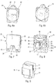
- the electronic release of the invention consists of a current measurement block 1 and an electronic processing block 2 of the current measurement.
- Such an electronic release integrates into an electrical line protection device, circuit breaker type, also having a breaking block.
- the measuring block 1 of current consists of a housing 6 containing sensors 9. It comprises a connecting face 20 to the treatment block 2, and two side faces 18,19.
- the lateral faces 18, 19 may be perpendicular to the connecting face 20.
- this measurement block 1 is adapted to operate in a three-pole circuit breaker since it has three identical sections 3,4,5, each section being provided for a pole.
- Each section 3,4,5 contains a current measuring sensor 9, which consists of a Rogowski winding, and a current transformer (not visible).
- the sensor 9 and the transformer consist of parts of revolution, more precisely tori, arranged coaxially.
- the size of the sensor 9 varies according to the size of the circuit breaker.
- the current transformer is used to feed electronic cards 14 contained in the processing block 2 which will be described later.
- the sensor 9 and the transformer comprise wire outputs connected to a male connector 8 housed in a reception area 7 provided for this purpose and protruding from the housing 6.
- This zone 7 is centered on each section 3,4,5 of the measurement block 1, in a transverse plane passing through the axis of the sensor 9 and the transformer.
- Said measurement block 1 and said processing block 2 extend essentially along a reference direction X.
- This male connector 8 plugs into a female connector 13 provided for this purpose in the electrical treatment block 2 of the current measurement.
- the processing block 2 consists of a housing 15 having a connection face 11 to the measurement block 1, as well as two lateral faces 16, 17.
- the lateral faces 16, 17 may be perpendicular to the connection face 11.
- This housing 15 encloses a plurality of electronic boards 14, fed by the transformers of the measurement block 1, and processing the incoming signals from the sensors 9 of the measurement block 1.
- the processing block 2 also comprises an intermediate lock 12, suitable to trigger the main lock of the circuit breaker (not shown), on the order of an electronic card 14 in the case where it detects a fault (overvoltage, short circuit).
- This processing block 2 exists in two versions. The difference between these two versions is the number of electronic cards related to the functions of the circuit breaker.
- a first version includes basic functions
- a second version includes basic functions plus advanced functions, such as voltage measurement for power calculation and communication.
- this processing unit 2 is adapted to operate in a three-pole circuit breaker since it has three identical sections 3,4,5, each section being provided for a pole.
- Each section 3,4,5 contains a female connector 13 disposed opposite a male connector 8 of the measurement block 1.
- the housing 15 is perforated at the female connectors 13 in order to leave them accessible for connection with the connectors 8.
- Each female connector 13 is directly attached to an electronic card 14 which therefore receives the current measurement information from the corresponding sensor 9 of the measurement block 1, and which is supplied via the corresponding transformer of the measurement block 1 .
- the electrical connection of the two blocks 1, 2 is therefore made by simply plugging the three male connectors 8 into the three female connectors 23, in a single direction of insertion, corresponding to the assembly direction of the blocks 1.2 and perpendicular to the reference direction X.
- the treatment block 2 comprises two connection plugs 21, 22 accessible from the outside via a day made in the case 15.
- connection plugs of a second type 22, 42 are used to add an internal neutral to the right or left of the electronic trigger, ie in front of or behind the electronic trigger, to obtain a four-pole trigger.
- a measuring extension 24 and a processing extension 25 are added on the right side of the measurement block 1 and / or the process block 2, ie in front of said measurement block 1 and / or said block of measurement. treatment 2 in the reference direction X.
- These two extensions 24,25 form a new section 23 provided for the pole relative to the neutral.
- This section 23 is aligned with the other sections 3,4,5, and adjoins the section 5.
- This new section 23 comprises, like the other sections 3,4,5, a current measuring sensor 9 and a current transformer, as well as a female connector 13, a male connector 8, and an electronic card. It is therefore equipped in the same way as the other sections 3,4,5.
- the electronic trigger thus formed of the four sections 3,4,5,23, has changed from a three-pole format to a four-pole format with the neutral on the right, that is to say in front of said measurement block 1 and said block of treatment 2 according to the reference direction X, while maintaining the same tripolar base structure to which unipolar extensions 24,25 were added.
- a measuring extension 24 and a processing extension 25 are added on the left side of the measurement block 1 and the processing block 2, ie behind said measurement block 1 and said treatment block 2 according to the reference direction X.
- These two extensions 24,25 form a new section 23 provided for the pole relative to the neutral.
- This section 23 is aligned with the other sections 3,4,5, and abuts the section 3.
- This new section 23 comprises, like the other sections 3,4,5, a current measuring sensor 9 and a current transformer, as well as a female connector 13, a male connector 8, and an electronic card. It is therefore equipped in the same way as the other sections 3,4,5.
- the electronic trip unit thus formed of the four sections 23, 3,4,5, has changed from a three-pole format to a four-pole format with the neutral on the left, ie behind said measurement block 1 and said block of treatment 2 according to the reference direction X, while maintaining the same tripolar base structure to which unipolar extensions 24,25 were added.
- the neutral is positioned to the right or to the left, that is to say in front of or behind said measurement block 1 and said processing block 2 in the reference direction X, the information coming from the processing extension 25, in particular the measurement of the current and the measurement of the voltage are recovered via the second type proximal plug 42, 22 of the processing block 2.
- the processing extension 25 can measure the voltage of the neutral, by means of an additional electronic card added in the treatment extension 25, and from which extends a flexible conductive blade which touches the terminal at the output of the extension cable.
- This additional electronic card is therefore able to send the information concerning the neutral voltage to the processing block 2.
- the treatment extension 25 consists of a housing having a connecting face 41 to the measuring extension 24, and two side faces 31,32.
- the lateral faces 31, 32 may be perpendicular to the connecting face 41.
- each side face 30,31 comprises a day 32,33 through which leaves of different types escape.
- the first lateral face 30 has a day 32 showing a connection plug of a first type 34, and which can escape a connection plug of a second type 28.
- the second lateral face 31 has a day 33 from which a connection plug of a first type 27 and the connection plug of a second type 28 can escape.
- the plug 27 consists of a female plug with two connection points. It is connected to the electronic card 26 via a wired link 40 consisting of two son connected to the tracks of the electronic card. These tracks are connected to the plug 34 which consists of a plug with two connection points, fixed to the electronic card and accessible since the day 32 of the first lateral face 30.
- the plug 28 consists of a female plug with five connection points. It is connected to the current measurement electronic board 26 via a wired link 29a consisting of four wires connected on tracks of this card 26, and to an additional electronic circuit board (not shown) for measuring voltage via a wire link 29b consisting of in a wire connected on a track of this map.
- the threads are sufficiently flexible to pass the plug 28 through the day 32 to the right or through the day 33 to the left, that is to say to pass the plug 28 through the day 32 in front of or behind said block of measurement 1 and said processing block 2 in the reference direction X, depending on the position of the treatment extension 25 with respect to the processing block 2.
- the length of the wires of the wired links 40 and 29 is not necessarily representative of the reality on this figure 8 .
- the figure 12 takes up the case of the figure 4 , with the neutral on the right, that is to say in front of said measurement block 1 and said processing block 2 in the reference direction X, the parts being separated in order to illustrate the wire links 40,29.
- the first lateral face 16 of the treatment block 2 is found opposite the second lateral face 31 of the treatment extension 25.
- the first type of connection plug 21 on the side face 16 of the treatment block 2 is offset on the side face 30 of the extension processing 25, which now corresponds to the outer edge of the electronic trigger.
- the first type connection plug 27 of the treatment extension 25 escapes via the day 33 and is plugged into the first type connection plug 21 present on the lateral face 16 of the treatment block 2 Via the electronic card 26 and the wire link 40, the information can pass between the plug 21 and the plug 34.
- the first type plug 34 on the side face 30 of the extension deport the functionality of the plug connector of first type 21 of the processing block 2. This functionality is thus always accessible from outside the trigger.
- the trip unit is configured as three-pole or four-pole with the right-hand neutral, that is, in front of said measurement block 1 and said processing block 2 in the reference direction X, this functionality is still accessible.
- the second type connection plug 28 escapes via the day 33 and is plugged into the second type connection plug 22 present on the side face 16 of the treatment block 2.
- the current and neutral voltage of the extension 25 are thus transferred via the electronic card 26 and the wire connection 29, to the plug 22.
- the figure 13 takes up the case of the figure 5 , with the neutral on the left, ie behind said measurement block 1 and said processing block 2 in the reference direction X, the pieces being separated in order to illustrate the wire connection 29.
- the second lateral face 17 of the processing block 2 is found opposite the first lateral face 30 of the treatment extension 25.
- the second type connection plug 28 escapes via the day 32 and is plugged into the second type connector plug 42 on the side face 17 of the treatment block 2.
- the current and voltage information of the neutral of the extension 25 are thus transferred via the electronic card 26 and the wire link 29, to the plug 42.
- the first type connection plugs 27, 34 are unused for this four-pole configuration with the neutral on the left, ie behind said measurement block 1 and said processing block 2 in the reference direction X
- the plug 27 and its wire link 40 are stored in the extension 25.
- the measuring extension 24 is illustrated more precisely in Figures 6a and 6b . It is fixed to the measurement block 1 by means of a support piece 35, or to the right, that is to say in front of said measurement block 1 and said processing block 2 in the reference direction X, as illustrated in FIG. figure 10 , or to the left, that is to say behind said measurement block 1 and said processing block 2 in the reference direction X, as illustrated in FIG. figure 11 .
- This support piece 35 consists of a symmetrical part comprising a partition wall of the measuring block 1 with respect to the measuring extension 24.
- the partition wall is provided on each side with hooking means for fixing on one side to the measuring block 1, and on the other side to the measuring extension 24. More precisely, in the upper part, two tabs 36,37 extend perpendicularly from the partition wall. In the lower part, two legs 38.39 extend perpendicularly of the partition wall. These tabs 36, 37, 38, 39 all have a notch in which a protruding return of the measuring block 1 and the measuring extension 24 can be seen.
- the tabs 37 and 39 are attached to the measuring block 1, and the tabs 36 and 38 are attached to the measuring extension 24.
- the tabs 36 and 38 are attached to the measuring block 1, and the tabs 37 and 39 are attached to the measuring extension 24.
- the processing extension 25 is fixed to the measuring extension 24.
- two tabs 43 in the shape of an L, visible in figure 7 extend from the connecting face 41 of the processing extension 25 towards the measuring extension 24.
- These two tabs 43 are disposed on either side of the female connector 13 and are able to slide in two recesses 44 of corresponding shape provided for this purpose on either side of the male connector 8 of the measuring extension 24, as illustrated in FIG. figure 6a .
- These tabs 43 allow locking in translation of an extension relative to the other in two directions perpendicular to the interlocking direction of the tabs 43 in the recesses 44.
Landscapes
- Breakers (AREA)
- Emergency Protection Circuit Devices (AREA)
- Details Of Connecting Devices For Male And Female Coupling (AREA)
Claims (15)
- Elektronischer Auslöser für elektrisches Mehrpolgerät zum Leitungsschutz vom Typ Schutzschalter, umfassend einen Strommessblock (1) und einen Block zur elektrischen Verarbeitung (2) der Strommessung, wobei der genannte Messblock (1) und der genannte Verarbeitungsblock (2) sich im Wesentlichen längs einer Bezugsrichtung (X) erstrecken, dadurch gekennzeichnet, dass der genannte Messblock (1) und der genannte Verarbeitungsblock (2) in aneinander angeschlossenen Dreipolblöcken bestehen und dadurch, dass der Auslöser Mittel zum Anfügen eines Nullleiters vor oder nach dem genannten Messblock (1) und/oder dem genannten Verarbeitungsblock (2) in der Bezugsrichtung (X) aufweist.
- Elektronischer Auslöser nach dem vorangehenden Patentanspruch, dadurch gekennzeichnet, dass die genannten Mittel zum Anfügen eines Nullleiters in einem ersten Mittel zum Anfügen eines Nullleiters vor oder nach dem genannten Messblock (1) und/oder dem genannten Verarbeitungsblock (2) in der Bezugsrichtung (X) bestehen und/oder in einem zweiten Mittel zum Anfügen eines Nullleiters vor oder nach dem genannten Messblock (1) und/oder dem genannten Verarbeitungsblock (2) in der Bezugsrichtung (X).
- Elektronischer Auslöser nach dem vorangehenden Patentanspruch, dadurch gekennzeichnet, dass das genannte erste Mittel zum Anfügen eines Nullleiters in einer einpoligen Messverlängerung (24) besteht, die vor oder nach dem genannten Messblock (1) und/oder dem genannten Verarbeitungsblock (2) in der Bezugsrichtung (X) angeordnet ist, und/oder dadurch, dass das genannte zweite Mittel zum Anfügen eines Nullleiters in einer einpoligen Verarbeitungsverlängerung (25) besteht, die vor oder nach dem genannten Messblock (1) und/oder dem genannten Verarbeitungsblock (2) in der Bezugsrichtung (X) angeordnet ist.
- Elektronischer Auslöser nach dem vorangehenden Patentanspruch, dadurch gekennzeichnet, dass die genannte Messverlängerung (24) am Messblock (1) befestigt und vom Messblock (1) mit Hilfe eines Tragstückes (35) elektrisch isoliert ist, das aus einem elektrisch isolierenden Werkstoff besteht.
- Elektronischer Auslöser nach dem vorangehenden Patentanspruch, dadurch gekennzeichnet, dass das genannte Tragstück (35) in einem symmetrischen Teil besteht, das eine Trennwand aufweist, die beiderseits mit Befestigungsmitteln (36, 37, 38, 39) versehen ist, um einerseits am Messblock (1) befestigt zu werden und andererseits an der Messverlängerung (24).
- Elektronischer Auslöser nach einem der Patentansprüche 3 bis 5, dadurch gekennzeichnet, dass die genannte Verarbeitungsverlängerung (25) mit Hilfe von Verbindungssteckern (27, 28, 21, 22, 42) am Verarbeitungsblock (2) elektrisch angeschlossen ist.
- Elektronischer Auslöser nach einem der vorangehenden Patentansprüche, dadurch gekennzeichnet, dass der Verarbeitungsblock (2) von einem Gehäuse (15) umgrenzt wird, das eine Fläche (11) zum Anschluss am Messblock (1) aufweist, sowie zwei vorzugsweise zur Anschlussfläche (11) senkrechte Seitenflächen (16, 17), wobei eine erste (16) der genannten Seitenflächen versehen ist mit:- einem Verbindungsstecker einer ersten Art (21), der den Zugriff auf eine besondere Funktion des Auslösers ermöglicht,- einem Verbindungsstecker einer zweiten Art (22), der ermöglicht, ein Hilfselement anzuschließen,während eine zweite (17) der genannten Seitenflächen versehen ist mit:- einem Verbindungsstecker einer zweiten Art, der mit dem (22) der ersten Seitenfläche (16) elektrisch verbunden ist.
- Elektronischer Auslöser nach einem der Patentansprüche 3 bis 6 in Kombination mit dem vorangehenden Patentanspruch, dadurch gekennzeichnet, dass die Verarbeitungsverlängerung (25) von einem Gehäuse umgrenzt wird, das eine Fläche (41) zum Anschluss an die Messverlängerung (24) aufweist, sowie zwei vorzugsweise zur Anschlussfläche (41) senkrechte Seitenflächen (30, 31), wobei eine erste (30) der genannten Seitenflächen mit einer Durchbrechung (32) versehen ist, die den Zugang ermöglicht zu:- einem Verbindungsstecker einer ersten Art (34),- einem Verbindungsstecker einer zweiten Art (28),während die zweite (31) der genannten Seitenflächen mit einer Durchbrechung (33) versehen ist, die den Zugang ermöglicht zu:- einem Verbindungsstecker einer ersten Art (27), der mit dem (34) der ersten Seitenfläche (30) elektrisch verbunden ist,- dem Verbindungsstecker einer zweiten Art (28),wobei alle Verbindungsstecker (34, 27, 28) an eine elektronische Schaltkarte (26) der Verarbeitungsverlängerung (25) angeschlossen sind.
- Elektronischer Auslöser nach dem vorangehenden Patentanspruch, dadurch gekennzeichnet, dass sich die erste Seitenfläche (16) des Verarbeitungsblockes (2) der zweiten Seitenfläche (31) der Verarbeitungsverlängerung (25) gegenüber befindet, wobei der Verbindungsstecker einer ersten Art (21) des Verarbeitungsblockes (2) sich in den Verbindungsstecker einer ersten Art (27) der Verarbeitungsverlängerung (25) einsteckt und der Verbindungsstecker einer zweiten Art (22) des Verarbeitungsblockes (2) sich in den Verbindungsstecker einer ersten Art (28) der Verarbeitungsverlängerung (25) einsteckt.
- Elektronischer Auslöser nach Patentanspruch 8, dadurch gekennzeichnet, dass sich die zweite Seitenfläche (17) des Verarbeitungsblockes (2) der ersten Seitenfläche (30) der Verarbeitungsverlängerung (25) gegenüber befindet, wobei der Verbindungsstecker einer zweiten Art (42) des Verarbeitungsblockes (2) sich in den Verbindungsstecker einer zweiten Art (28) der Verarbeitungsverlängerung (25) einsteckt.
- Elektronischer Auslöser nach irgendeinem der Patentansprüche 8 bis 10, dadurch gekennzeichnet, dass sich der Verbindungsstecker einer zweiten Art (28) der Verarbeitungsverlängerung (25) unabhängig von der Stellung der Verarbeitungsverlängerung (25) relativ zum Verarbeitungsblock (2) in den entsprechenden Verbindungsstecker einer zweiten Art (22, 42) des Verarbeitungsblockes (2) einsteckt.
- Elektronischer Auslöser nach einem der Patentansprüche 3 bis 6 und 8 bis 11 oder nach Patentanspruch 3 in Kombination mit Patentanspruch 7, dadurch gekennzeichnet, dass er über elektrische Verbindungsmittel zwischen dem Messblock (1) und dem Verarbeitungsblock (2) verfügt, die für jeden Pol in einem dem Messblock (1) angehörenden Stecker (8) bestehen, der sich in eine dem Verarbeitungsblock (2) angehörende Buchse (13) einsteckt.
- Elektronischer Auslöser nach einem der Patentansprüche 3 bis 6 und 8 bis 12 oder nach Patentanspruch 3 in Kombination mit Patentanspruch 7, dadurch gekennzeichnet, dass er über elektrische Verbindungsmittel zwischen der Messverlängerung (24) und der Verarbeitungsverlängerung (25) verfügt, die für jeden Pol in einem der Messverlängerung (24) angehörenden Stecker (8) bestehen, der sich in eine der Verarbeitungsverlängerung (25) angehörende Buchse (13) einsteckt.
- Elektronischer Auslöser nach dem vorangehenden Patentansprüche, dadurch gekennzeichnet, dass die Verarbeitungsverlängerung (25) mit Hilfe zweier Klauen (43), die beiderseits der Buchse (13) angeordnet sind und die in der Lage sind, sich in zwei Ausnehmungen (44) entsprechender Form einzufügen, die zu diesem Zweck beiderseits des Steckers (8) vorgesehen sind, an der Messverlängerung (24) befestigt ist.
- Elektrischer Leitungsschutzapparat vom Typ Schutzschalter , einen Unterbrecherblock und einen elektronischen Auslöser, wie in irgendeinem der vorangehenden Patentansprüche beschrieben, umfassend.
Applications Claiming Priority (2)
| Application Number | Priority Date | Filing Date | Title |
|---|---|---|---|
| FR1657428A FR3054716B1 (fr) | 2016-07-29 | 2016-07-29 | Declencheur electronique pour appareil electrique de protection de ligne |
| PCT/FR2017/050291 WO2018020086A1 (fr) | 2016-07-29 | 2017-02-09 | Déclencheur électronique pour appareil électrique de protection de ligne |
Publications (2)
| Publication Number | Publication Date |
|---|---|
| EP3300529A1 EP3300529A1 (de) | 2018-04-04 |
| EP3300529B1 true EP3300529B1 (de) | 2019-04-17 |
Family
ID=57906685
Family Applications (1)
| Application Number | Title | Priority Date | Filing Date |
|---|---|---|---|
| EP17709130.3A Active EP3300529B1 (de) | 2016-07-29 | 2017-02-09 | Elektronische auslösungsvorrichtung für eine stromleitungsschutzvorrichtung |
Country Status (5)
| Country | Link |
|---|---|
| EP (1) | EP3300529B1 (de) |
| JP (1) | JP6916863B2 (de) |
| CN (1) | CN109314019B (de) |
| FR (1) | FR3054716B1 (de) |
| WO (1) | WO2018020086A1 (de) |
Family Cites Families (7)
| Publication number | Priority date | Publication date | Assignee | Title |
|---|---|---|---|---|
| FR2624666B1 (de) * | 1987-12-10 | 1990-04-06 | Merlin Gerin | |
| FR2739973B1 (fr) * | 1995-10-11 | 1997-12-05 | Schneider Electric Sa | Ensemble de connexion |
| DE10210920B4 (de) * | 2002-03-13 | 2005-02-03 | Moeller Gmbh | Leistungsschalter mit elektronischem Auslöser |
| DE102006059384B4 (de) * | 2006-12-15 | 2013-02-21 | Siemens Aktiengesellschaft | Gerät mit einem Stromwandler zur Erfassung eines durch einen Stromleiter fließenden Stromes sowie Klemmen-/Stromwandler-Modul für ein derartiges Gerät |
| ITMI20080419U1 (it) * | 2008-12-18 | 2010-06-18 | Abb Spa | Dispositivo di commutazione elettrica per circuiti di bassa tensione |
| DE102010019533B4 (de) * | 2010-05-06 | 2015-01-15 | Eaton Industries Gmbh | Strommessverfahren für ein Schaltgerät mit parallel geschalteten Strombahnen |
| KR101104103B1 (ko) * | 2011-11-08 | 2012-01-12 | 주식회사 비엠티 | 모듈형 안전부스바 |
-
2016
- 2016-07-29 FR FR1657428A patent/FR3054716B1/fr active Active
-
2017
- 2017-02-09 EP EP17709130.3A patent/EP3300529B1/de active Active
- 2017-02-09 CN CN201780035987.2A patent/CN109314019B/zh active Active
- 2017-02-09 WO PCT/FR2017/050291 patent/WO2018020086A1/fr not_active Ceased
- 2017-02-09 JP JP2019504847A patent/JP6916863B2/ja active Active
Non-Patent Citations (1)
| Title |
|---|
| None * |
Also Published As
| Publication number | Publication date |
|---|---|
| EP3300529A1 (de) | 2018-04-04 |
| FR3054716A1 (fr) | 2018-02-02 |
| WO2018020086A1 (fr) | 2018-02-01 |
| CN109314019A (zh) | 2019-02-05 |
| FR3054716B1 (fr) | 2018-09-07 |
| JP6916863B2 (ja) | 2021-08-11 |
| CN109314019B (zh) | 2022-03-01 |
| JP2019530134A (ja) | 2019-10-17 |
Similar Documents
| Publication | Publication Date | Title |
|---|---|---|
| FR2815767A1 (fr) | Sectionneur a fusible compact | |
| EP0493272B1 (de) | Schutzschalter mit einer Schnittstellenkarte für einen Auslöser | |
| EP3470856B1 (de) | Modul zur detektion einer elektrischen störung für eine elektrische schutzanordnung, und elektrische schutzanordnung, die ein solches detektionsmodul umfasst | |
| FR2778473A1 (fr) | Procede permettant la communication d'un multimetre portatif et d'un ordinateur via un connecteur d'entree-sortie de mesure | |
| EP3300529B1 (de) | Elektronische auslösungsvorrichtung für eine stromleitungsschutzvorrichtung | |
| EP3361268B1 (de) | Überwachungsschaltung für ein stromnetzes | |
| EP3264118B1 (de) | Überwachungssystem eines stromnetzes | |
| EP3420619B1 (de) | Flugzeug mit einem elektrischen gleichstromnetzwerk und system zum schutz dieses netzwerks | |
| WO2019122187A1 (fr) | Appareil auxiliaire pour appareillage de protection électrique | |
| WO2013087443A1 (fr) | Parafoudre tripolaire integre dans une passerelle residentielle avec detecteur d'impact de foudre | |
| EP3300531B1 (de) | Elektronische auslösungsvorrichtung für eine stromleitungsschutzvorrichtung | |
| WO2001050140A2 (fr) | Prise de test electrique, appareillage et systeme mettant en oeuvre une telle prise | |
| FR3080494A1 (fr) | Dispositif de raccordement pour appareil electrique, appareil electrique comprenant ledit dispositif de raccordement et coffret de distribution associe | |
| WO2024194096A1 (fr) | Unité électronique de détection d'au moins un défaut électrique pour un appareillage électrique de protection au format modulaire et appareillage électrique de protection au format modulaire associé | |
| EP4730583A1 (de) | Elektrische schutzvorrichtung, schaltanlage und schalttafel dafür | |
| EP4625459A1 (de) | Steuereinheit für einen elektrischen schutzschalter und elektrischer schutzschalter dafür | |
| EP4350721A1 (de) | Magnetischer stromsensor, mischstromsensor mit einem solchen magnetischen stromsensor und schutzschalter mit einem solchen mischstromsensor | |
| EP3435398B1 (de) | Elektrisches differentialschutzgerät | |
| EP1026793B1 (de) | Verbindungsanordnung für einen Schutzschalter | |
| FR3030913A1 (fr) | Dispositif d'alimentation electrique securise comprenant un support de distribution et un connecteur | |
| BE893923A (fr) | Dispositif d'essai de lignes et de protection d'appareils. | |
| EP4625460A1 (de) | Steuereinheit für einen elektrischen schutzschalter und elektrischer schutzschalter dafür | |
| FR3101194A1 (fr) | Appareil de coupure électrique à fusible | |
| FR2868889A1 (fr) | Dispositif de mise a la terre automatique du point neutre d'un transformateur hta/bt | |
| EP4738408A1 (de) | Öffnungsdetektionsvorrichtung |
Legal Events
| Date | Code | Title | Description |
|---|---|---|---|
| STAA | Information on the status of an ep patent application or granted ep patent |
Free format text: STATUS: UNKNOWN |
|
| STAA | Information on the status of an ep patent application or granted ep patent |
Free format text: STATUS: THE INTERNATIONAL PUBLICATION HAS BEEN MADE |
|
| PUAI | Public reference made under article 153(3) epc to a published international application that has entered the european phase |
Free format text: ORIGINAL CODE: 0009012 |
|
| STAA | Information on the status of an ep patent application or granted ep patent |
Free format text: STATUS: REQUEST FOR EXAMINATION WAS MADE |
|
| 17P | Request for examination filed |
Effective date: 20171228 |
|
| AK | Designated contracting states |
Kind code of ref document: A1 Designated state(s): AL AT BE BG CH CY CZ DE DK EE ES FI FR GB GR HR HU IE IS IT LI LT LU LV MC MK MT NL NO PL PT RO RS SE SI SK SM TR |
|
| AX | Request for extension of the european patent |
Extension state: BA ME |
|
| RIN1 | Information on inventor provided before grant (corrected) |
Inventor name: STOCKER, GILLES |
|
| RAP1 | Party data changed (applicant data changed or rights of an application transferred) |
Owner name: HAGER-ELECTRO SAS |
|
| 111L | Licence recorded |
Designated state(s): AL AT BE BG CH CY CZ DE DK EE ES FI FR GB GR HR HU IE IS IT LT LU LV MC MK MT NL NO PL PT RO RS SE SI SK SM TR Name of requester: TERASAKI ELECTRIC CO. LIMITED, JP Effective date: 20180629 |
|
| GRAP | Despatch of communication of intention to grant a patent |
Free format text: ORIGINAL CODE: EPIDOSNIGR1 |
|
| STAA | Information on the status of an ep patent application or granted ep patent |
Free format text: STATUS: GRANT OF PATENT IS INTENDED |
|
| RIC1 | Information provided on ipc code assigned before grant |
Ipc: H01H 71/12 20060101ALI20181009BHEP Ipc: H01H 71/02 20060101AFI20181009BHEP |
|
| DAX | Request for extension of the european patent (deleted) | ||
| INTG | Intention to grant announced |
Effective date: 20181113 |
|
| GRAS | Grant fee paid |
Free format text: ORIGINAL CODE: EPIDOSNIGR3 |
|
| GRAA | (expected) grant |
Free format text: ORIGINAL CODE: 0009210 |
|
| STAA | Information on the status of an ep patent application or granted ep patent |
Free format text: STATUS: THE PATENT HAS BEEN GRANTED |
|
| DAV | Request for validation of the european patent (deleted) | ||
| 111L | Licence recorded |
Designated state(s): AL AT BE BG CH CY CZ DE DK EE ES FI FR GB GR HR HU IE IS IT LT LU LV MC MK MT NL NO PL PT RO RS SE SI SK SM TR Name of requester: TERASAKI ELECTRIC CO. LIMITED, JP Effective date: 20180629 |
|
| AK | Designated contracting states |
Kind code of ref document: B1 Designated state(s): AL AT BE BG CH CY CZ DE DK EE ES FI FR GB GR HR HU IE IS IT LI LT LU LV MC MK MT NL NO PL PT RO RS SE SI SK SM TR |
|
| REG | Reference to a national code |
Ref country code: GB Ref legal event code: FG4D Free format text: NOT ENGLISH |
|
| REG | Reference to a national code |
Ref country code: CH Ref legal event code: EP |
|
| REG | Reference to a national code |
Ref country code: DE Ref legal event code: R096 Ref document number: 602017003386 Country of ref document: DE |
|
| REG | Reference to a national code |
Ref country code: AT Ref legal event code: REF Ref document number: 1122472 Country of ref document: AT Kind code of ref document: T Effective date: 20190515 Ref country code: IE Ref legal event code: FG4D Free format text: LANGUAGE OF EP DOCUMENT: FRENCH |
|
| REG | Reference to a national code |
Ref country code: CH Ref legal event code: NV Representative=s name: DR. GRAF AND PARTNER AG INTELLECTUAL PROPERTY, CH |
|
| REG | Reference to a national code |
Ref country code: NL Ref legal event code: MP Effective date: 20190417 |
|
| REG | Reference to a national code |
Ref country code: LT Ref legal event code: MG4D |
|
| PG25 | Lapsed in a contracting state [announced via postgrant information from national office to epo] |
Ref country code: NL Free format text: LAPSE BECAUSE OF FAILURE TO SUBMIT A TRANSLATION OF THE DESCRIPTION OR TO PAY THE FEE WITHIN THE PRESCRIBED TIME-LIMIT Effective date: 20190417 |
|
| PG25 | Lapsed in a contracting state [announced via postgrant information from national office to epo] |
Ref country code: LT Free format text: LAPSE BECAUSE OF FAILURE TO SUBMIT A TRANSLATION OF THE DESCRIPTION OR TO PAY THE FEE WITHIN THE PRESCRIBED TIME-LIMIT Effective date: 20190417 Ref country code: HR Free format text: LAPSE BECAUSE OF FAILURE TO SUBMIT A TRANSLATION OF THE DESCRIPTION OR TO PAY THE FEE WITHIN THE PRESCRIBED TIME-LIMIT Effective date: 20190417 Ref country code: NO Free format text: LAPSE BECAUSE OF FAILURE TO SUBMIT A TRANSLATION OF THE DESCRIPTION OR TO PAY THE FEE WITHIN THE PRESCRIBED TIME-LIMIT Effective date: 20190717 Ref country code: SE Free format text: LAPSE BECAUSE OF FAILURE TO SUBMIT A TRANSLATION OF THE DESCRIPTION OR TO PAY THE FEE WITHIN THE PRESCRIBED TIME-LIMIT Effective date: 20190417 Ref country code: FI Free format text: LAPSE BECAUSE OF FAILURE TO SUBMIT A TRANSLATION OF THE DESCRIPTION OR TO PAY THE FEE WITHIN THE PRESCRIBED TIME-LIMIT Effective date: 20190417 Ref country code: AL Free format text: LAPSE BECAUSE OF FAILURE TO SUBMIT A TRANSLATION OF THE DESCRIPTION OR TO PAY THE FEE WITHIN THE PRESCRIBED TIME-LIMIT Effective date: 20190417 Ref country code: PT Free format text: LAPSE BECAUSE OF FAILURE TO SUBMIT A TRANSLATION OF THE DESCRIPTION OR TO PAY THE FEE WITHIN THE PRESCRIBED TIME-LIMIT Effective date: 20190817 Ref country code: ES Free format text: LAPSE BECAUSE OF FAILURE TO SUBMIT A TRANSLATION OF THE DESCRIPTION OR TO PAY THE FEE WITHIN THE PRESCRIBED TIME-LIMIT Effective date: 20190417 |
|
| PG25 | Lapsed in a contracting state [announced via postgrant information from national office to epo] |
Ref country code: BG Free format text: LAPSE BECAUSE OF FAILURE TO SUBMIT A TRANSLATION OF THE DESCRIPTION OR TO PAY THE FEE WITHIN THE PRESCRIBED TIME-LIMIT Effective date: 20190717 Ref country code: RS Free format text: LAPSE BECAUSE OF FAILURE TO SUBMIT A TRANSLATION OF THE DESCRIPTION OR TO PAY THE FEE WITHIN THE PRESCRIBED TIME-LIMIT Effective date: 20190417 Ref country code: PL Free format text: LAPSE BECAUSE OF FAILURE TO SUBMIT A TRANSLATION OF THE DESCRIPTION OR TO PAY THE FEE WITHIN THE PRESCRIBED TIME-LIMIT Effective date: 20190417 Ref country code: GR Free format text: LAPSE BECAUSE OF FAILURE TO SUBMIT A TRANSLATION OF THE DESCRIPTION OR TO PAY THE FEE WITHIN THE PRESCRIBED TIME-LIMIT Effective date: 20190718 Ref country code: LV Free format text: LAPSE BECAUSE OF FAILURE TO SUBMIT A TRANSLATION OF THE DESCRIPTION OR TO PAY THE FEE WITHIN THE PRESCRIBED TIME-LIMIT Effective date: 20190417 |
|
| REG | Reference to a national code |
Ref country code: AT Ref legal event code: MK05 Ref document number: 1122472 Country of ref document: AT Kind code of ref document: T Effective date: 20190417 |
|
| PG25 | Lapsed in a contracting state [announced via postgrant information from national office to epo] |
Ref country code: IS Free format text: LAPSE BECAUSE OF FAILURE TO SUBMIT A TRANSLATION OF THE DESCRIPTION OR TO PAY THE FEE WITHIN THE PRESCRIBED TIME-LIMIT Effective date: 20190817 |
|
| REG | Reference to a national code |
Ref country code: DE Ref legal event code: R097 Ref document number: 602017003386 Country of ref document: DE |
|
| PG25 | Lapsed in a contracting state [announced via postgrant information from national office to epo] |
Ref country code: DK Free format text: LAPSE BECAUSE OF FAILURE TO SUBMIT A TRANSLATION OF THE DESCRIPTION OR TO PAY THE FEE WITHIN THE PRESCRIBED TIME-LIMIT Effective date: 20190417 Ref country code: AT Free format text: LAPSE BECAUSE OF FAILURE TO SUBMIT A TRANSLATION OF THE DESCRIPTION OR TO PAY THE FEE WITHIN THE PRESCRIBED TIME-LIMIT Effective date: 20190417 Ref country code: CZ Free format text: LAPSE BECAUSE OF FAILURE TO SUBMIT A TRANSLATION OF THE DESCRIPTION OR TO PAY THE FEE WITHIN THE PRESCRIBED TIME-LIMIT Effective date: 20190417 Ref country code: RO Free format text: LAPSE BECAUSE OF FAILURE TO SUBMIT A TRANSLATION OF THE DESCRIPTION OR TO PAY THE FEE WITHIN THE PRESCRIBED TIME-LIMIT Effective date: 20190417 Ref country code: EE Free format text: LAPSE BECAUSE OF FAILURE TO SUBMIT A TRANSLATION OF THE DESCRIPTION OR TO PAY THE FEE WITHIN THE PRESCRIBED TIME-LIMIT Effective date: 20190417 Ref country code: SK Free format text: LAPSE BECAUSE OF FAILURE TO SUBMIT A TRANSLATION OF THE DESCRIPTION OR TO PAY THE FEE WITHIN THE PRESCRIBED TIME-LIMIT Effective date: 20190417 |
|
| PLBE | No opposition filed within time limit |
Free format text: ORIGINAL CODE: 0009261 |
|
| STAA | Information on the status of an ep patent application or granted ep patent |
Free format text: STATUS: NO OPPOSITION FILED WITHIN TIME LIMIT |
|
| PG25 | Lapsed in a contracting state [announced via postgrant information from national office to epo] |
Ref country code: SM Free format text: LAPSE BECAUSE OF FAILURE TO SUBMIT A TRANSLATION OF THE DESCRIPTION OR TO PAY THE FEE WITHIN THE PRESCRIBED TIME-LIMIT Effective date: 20190417 Ref country code: IT Free format text: LAPSE BECAUSE OF FAILURE TO SUBMIT A TRANSLATION OF THE DESCRIPTION OR TO PAY THE FEE WITHIN THE PRESCRIBED TIME-LIMIT Effective date: 20190417 |
|
| 26N | No opposition filed |
Effective date: 20200120 |
|
| PG25 | Lapsed in a contracting state [announced via postgrant information from national office to epo] |
Ref country code: TR Free format text: LAPSE BECAUSE OF FAILURE TO SUBMIT A TRANSLATION OF THE DESCRIPTION OR TO PAY THE FEE WITHIN THE PRESCRIBED TIME-LIMIT Effective date: 20190417 |
|
| PG25 | Lapsed in a contracting state [announced via postgrant information from national office to epo] |
Ref country code: SI Free format text: LAPSE BECAUSE OF FAILURE TO SUBMIT A TRANSLATION OF THE DESCRIPTION OR TO PAY THE FEE WITHIN THE PRESCRIBED TIME-LIMIT Effective date: 20190417 |
|
| REG | Reference to a national code |
Ref country code: BE Ref legal event code: MM Effective date: 20200229 |
|
| PG25 | Lapsed in a contracting state [announced via postgrant information from national office to epo] |
Ref country code: LU Free format text: LAPSE BECAUSE OF NON-PAYMENT OF DUE FEES Effective date: 20200209 Ref country code: MC Free format text: LAPSE BECAUSE OF FAILURE TO SUBMIT A TRANSLATION OF THE DESCRIPTION OR TO PAY THE FEE WITHIN THE PRESCRIBED TIME-LIMIT Effective date: 20190417 |
|
| PG25 | Lapsed in a contracting state [announced via postgrant information from national office to epo] |
Ref country code: IE Free format text: LAPSE BECAUSE OF NON-PAYMENT OF DUE FEES Effective date: 20200209 |
|
| PG25 | Lapsed in a contracting state [announced via postgrant information from national office to epo] |
Ref country code: BE Free format text: LAPSE BECAUSE OF NON-PAYMENT OF DUE FEES Effective date: 20200229 |
|
| GBPC | Gb: european patent ceased through non-payment of renewal fee |
Effective date: 20210209 |
|
| PG25 | Lapsed in a contracting state [announced via postgrant information from national office to epo] |
Ref country code: GB Free format text: LAPSE BECAUSE OF NON-PAYMENT OF DUE FEES Effective date: 20210209 |
|
| PG25 | Lapsed in a contracting state [announced via postgrant information from national office to epo] |
Ref country code: MT Free format text: LAPSE BECAUSE OF FAILURE TO SUBMIT A TRANSLATION OF THE DESCRIPTION OR TO PAY THE FEE WITHIN THE PRESCRIBED TIME-LIMIT Effective date: 20190417 Ref country code: CY Free format text: LAPSE BECAUSE OF FAILURE TO SUBMIT A TRANSLATION OF THE DESCRIPTION OR TO PAY THE FEE WITHIN THE PRESCRIBED TIME-LIMIT Effective date: 20190417 |
|
| PG25 | Lapsed in a contracting state [announced via postgrant information from national office to epo] |
Ref country code: MK Free format text: LAPSE BECAUSE OF FAILURE TO SUBMIT A TRANSLATION OF THE DESCRIPTION OR TO PAY THE FEE WITHIN THE PRESCRIBED TIME-LIMIT Effective date: 20190417 |
|
| P01 | Opt-out of the competence of the unified patent court (upc) registered |
Effective date: 20230606 |
|
| REG | Reference to a national code |
Ref country code: CH Ref legal event code: U11 Free format text: ST27 STATUS EVENT CODE: U-0-0-U10-U11 (AS PROVIDED BY THE NATIONAL OFFICE) Effective date: 20260301 |
|
| PGFP | Annual fee paid to national office [announced via postgrant information from national office to epo] |
Ref country code: DE Payment date: 20260227 Year of fee payment: 10 |
|
| PGFP | Annual fee paid to national office [announced via postgrant information from national office to epo] |
Ref country code: FR Payment date: 20260225 Year of fee payment: 10 |
|
| PGFP | Annual fee paid to national office [announced via postgrant information from national office to epo] |
Ref country code: CH Payment date: 20260301 Year of fee payment: 10 |