EP3300669A1 - Dispositif et procédé de fermeture étanche d'une membrane - Google Patents
Dispositif et procédé de fermeture étanche d'une membrane Download PDFInfo
- Publication number
- EP3300669A1 EP3300669A1 EP17154743.3A EP17154743A EP3300669A1 EP 3300669 A1 EP3300669 A1 EP 3300669A1 EP 17154743 A EP17154743 A EP 17154743A EP 3300669 A1 EP3300669 A1 EP 3300669A1
- Authority
- EP
- European Patent Office
- Prior art keywords
- membrane
- patch
- closure device
- fastener
- perforation
- Prior art date
- Legal status (The legal status is an assumption and is not a legal conclusion. Google has not performed a legal analysis and makes no representation as to the accuracy of the status listed.)
- Withdrawn
Links
- 239000012528 membrane Substances 0.000 title claims abstract description 130
- 238000000034 method Methods 0.000 title claims description 26
- 238000007789 sealing Methods 0.000 title description 6
- 230000007246 mechanism Effects 0.000 claims abstract description 48
- 210000004379 membrane Anatomy 0.000 claims description 127
- 239000003292 glue Substances 0.000 claims description 24
- 238000002156 mixing Methods 0.000 claims description 15
- 239000000565 sealant Substances 0.000 claims description 14
- 210000002219 extraembryonic membrane Anatomy 0.000 claims description 12
- 239000000463 material Substances 0.000 claims description 12
- 239000000853 adhesive Substances 0.000 claims description 10
- 230000001070 adhesive effect Effects 0.000 claims description 10
- 229910001000 nickel titanium Inorganic materials 0.000 claims description 7
- HLXZNVUGXRDIFK-UHFFFAOYSA-N nickel titanium Chemical compound [Ti].[Ti].[Ti].[Ti].[Ti].[Ti].[Ti].[Ti].[Ti].[Ti].[Ti].[Ni].[Ni].[Ni].[Ni].[Ni].[Ni].[Ni].[Ni].[Ni].[Ni].[Ni].[Ni].[Ni].[Ni] HLXZNVUGXRDIFK-UHFFFAOYSA-N 0.000 claims description 7
- 230000001939 inductive effect Effects 0.000 claims description 6
- 230000035876 healing Effects 0.000 claims description 5
- 239000000203 mixture Substances 0.000 claims description 5
- 210000001691 amnion Anatomy 0.000 claims description 3
- 230000002526 effect on cardiovascular system Effects 0.000 claims description 3
- 239000003102 growth factor Substances 0.000 claims description 3
- 239000012781 shape memory material Substances 0.000 claims description 3
- 210000003454 tympanic membrane Anatomy 0.000 claims description 3
- 230000002792 vascular Effects 0.000 claims description 3
- 230000014759 maintenance of location Effects 0.000 description 15
- 230000008878 coupling Effects 0.000 description 10
- 238000010168 coupling process Methods 0.000 description 10
- 238000005859 coupling reaction Methods 0.000 description 10
- 230000000670 limiting effect Effects 0.000 description 7
- 238000002347 injection Methods 0.000 description 6
- 239000007924 injection Substances 0.000 description 6
- 238000004146 energy storage Methods 0.000 description 5
- 239000012530 fluid Substances 0.000 description 5
- 238000004026 adhesive bonding Methods 0.000 description 4
- 230000036760 body temperature Effects 0.000 description 4
- 229910000734 martensite Inorganic materials 0.000 description 4
- 229920001296 polysiloxane Polymers 0.000 description 4
- 230000000717 retained effect Effects 0.000 description 4
- 210000001519 tissue Anatomy 0.000 description 4
- 229910001566 austenite Inorganic materials 0.000 description 3
- 210000004027 cell Anatomy 0.000 description 3
- 238000005520 cutting process Methods 0.000 description 3
- 238000005516 engineering process Methods 0.000 description 3
- 238000000338 in vitro Methods 0.000 description 3
- 108010004563 mussel adhesive protein Proteins 0.000 description 3
- 230000035935 pregnancy Effects 0.000 description 3
- 229920000936 Agarose Polymers 0.000 description 2
- 108010035532 Collagen Proteins 0.000 description 2
- 102000008186 Collagen Human genes 0.000 description 2
- 208000032589 Diaphragmatic Congenital Hernias Diseases 0.000 description 2
- 108010080379 Fibrin Tissue Adhesive Proteins 0.000 description 2
- -1 Polytetrafluorethylen Polymers 0.000 description 2
- 241000220317 Rosa Species 0.000 description 2
- 208000027418 Wounds and injury Diseases 0.000 description 2
- 210000004381 amniotic fluid Anatomy 0.000 description 2
- 238000013459 approach Methods 0.000 description 2
- 230000003592 biomimetic effect Effects 0.000 description 2
- 229920001436 collagen Polymers 0.000 description 2
- 201000005890 congenital diaphragmatic hernia Diseases 0.000 description 2
- 238000010586 diagram Methods 0.000 description 2
- 201000010099 disease Diseases 0.000 description 2
- 208000037265 diseases, disorders, signs and symptoms Diseases 0.000 description 2
- 210000003754 fetus Anatomy 0.000 description 2
- 239000007788 liquid Substances 0.000 description 2
- 238000002324 minimally invasive surgery Methods 0.000 description 2
- 239000002861 polymer material Substances 0.000 description 2
- 238000003825 pressing Methods 0.000 description 2
- 230000007704 transition Effects 0.000 description 2
- RYGMFSIKBFXOCR-UHFFFAOYSA-N Copper Chemical compound [Cu] RYGMFSIKBFXOCR-UHFFFAOYSA-N 0.000 description 1
- 208000002757 Fetofetal Transfusion Diseases 0.000 description 1
- 108010073385 Fibrin Proteins 0.000 description 1
- 102000009123 Fibrin Human genes 0.000 description 1
- BWGVNKXGVNDBDI-UHFFFAOYSA-N Fibrin monomer Chemical compound CNC(=O)CNC(=O)CN BWGVNKXGVNDBDI-UHFFFAOYSA-N 0.000 description 1
- 239000001828 Gelatine Substances 0.000 description 1
- 208000005107 Premature Birth Diseases 0.000 description 1
- 108090000190 Thrombin Proteins 0.000 description 1
- 102000004887 Transforming Growth Factor beta Human genes 0.000 description 1
- 108090001012 Transforming Growth Factor beta Proteins 0.000 description 1
- 230000004913 activation Effects 0.000 description 1
- 230000004888 barrier function Effects 0.000 description 1
- 230000003542 behavioural effect Effects 0.000 description 1
- 238000005452 bending Methods 0.000 description 1
- 230000008901 benefit Effects 0.000 description 1
- 238000009954 braiding Methods 0.000 description 1
- 206010008129 cerebral palsy Diseases 0.000 description 1
- 230000001684 chronic effect Effects 0.000 description 1
- 230000001149 cognitive effect Effects 0.000 description 1
- 238000004891 communication Methods 0.000 description 1
- 230000000295 complement effect Effects 0.000 description 1
- 230000006835 compression Effects 0.000 description 1
- 238000007906 compression Methods 0.000 description 1
- 238000010276 construction Methods 0.000 description 1
- 229910052802 copper Inorganic materials 0.000 description 1
- 239000010949 copper Substances 0.000 description 1
- 238000004132 cross linking Methods 0.000 description 1
- 230000006378 damage Effects 0.000 description 1
- 230000003247 decreasing effect Effects 0.000 description 1
- 230000007547 defect Effects 0.000 description 1
- 238000011161 development Methods 0.000 description 1
- 238000003745 diagnosis Methods 0.000 description 1
- 238000003618 dip coating Methods 0.000 description 1
- 238000001523 electrospinning Methods 0.000 description 1
- 238000002474 experimental method Methods 0.000 description 1
- 230000001605 fetal effect Effects 0.000 description 1
- 229950003499 fibrin Drugs 0.000 description 1
- 230000006870 function Effects 0.000 description 1
- 229920000159 gelatin Polymers 0.000 description 1
- 235000019322 gelatine Nutrition 0.000 description 1
- 230000036541 health Effects 0.000 description 1
- 238000010438 heat treatment Methods 0.000 description 1
- 230000000642 iatrogenic effect Effects 0.000 description 1
- 230000001771 impaired effect Effects 0.000 description 1
- 208000015181 infectious disease Diseases 0.000 description 1
- 208000014674 injury Diseases 0.000 description 1
- 238000003780 insertion Methods 0.000 description 1
- 230000037431 insertion Effects 0.000 description 1
- 238000003698 laser cutting Methods 0.000 description 1
- 238000002430 laser surgery Methods 0.000 description 1
- 231100000518 lethal Toxicity 0.000 description 1
- 230000001665 lethal effect Effects 0.000 description 1
- 239000000314 lubricant Substances 0.000 description 1
- 210000001161 mammalian embryo Anatomy 0.000 description 1
- 238000004519 manufacturing process Methods 0.000 description 1
- 108010082117 matrigel Proteins 0.000 description 1
- 239000002184 metal Substances 0.000 description 1
- 229910052751 metal Inorganic materials 0.000 description 1
- 238000010327 methods by industry Methods 0.000 description 1
- 238000012986 modification Methods 0.000 description 1
- 230000004048 modification Effects 0.000 description 1
- 229920005615 natural polymer Polymers 0.000 description 1
- 231100000252 nontoxic Toxicity 0.000 description 1
- 230000003000 nontoxic effect Effects 0.000 description 1
- 230000014306 paracrine signaling Effects 0.000 description 1
- 230000010412 perfusion Effects 0.000 description 1
- 239000012466 permeate Substances 0.000 description 1
- 230000003169 placental effect Effects 0.000 description 1
- 210000004623 platelet-rich plasma Anatomy 0.000 description 1
- 238000002360 preparation method Methods 0.000 description 1
- 230000008569 process Effects 0.000 description 1
- 230000001902 propagating effect Effects 0.000 description 1
- 230000005855 radiation Effects 0.000 description 1
- 230000002441 reversible effect Effects 0.000 description 1
- 229910001285 shape-memory alloy Inorganic materials 0.000 description 1
- 239000002002 slurry Substances 0.000 description 1
- 230000002269 spontaneous effect Effects 0.000 description 1
- 230000003068 static effect Effects 0.000 description 1
- 230000000638 stimulation Effects 0.000 description 1
- 238000011477 surgical intervention Methods 0.000 description 1
- 238000001356 surgical procedure Methods 0.000 description 1
- 229920002994 synthetic fiber Polymers 0.000 description 1
- 229920001059 synthetic polymer Polymers 0.000 description 1
- 238000012360 testing method Methods 0.000 description 1
- ZRKFYGHZFMAOKI-QMGMOQQFSA-N tgfbeta Chemical compound C([C@H](NC(=O)[C@H](C(C)C)NC(=O)CNC(=O)[C@H](CCC(O)=O)NC(=O)[C@H](CCCNC(N)=N)NC(=O)[C@H](CC(N)=O)NC(=O)[C@H](CC(C)C)NC(=O)[C@H]([C@@H](C)O)NC(=O)[C@H](CCC(O)=O)NC(=O)[C@H]([C@@H](C)O)NC(=O)[C@H](CC(C)C)NC(=O)CNC(=O)[C@H](C)NC(=O)[C@H](CO)NC(=O)[C@H](CCC(N)=O)NC(=O)[C@@H](NC(=O)[C@H](C)NC(=O)[C@H](C)NC(=O)[C@@H](NC(=O)[C@H](CC(C)C)NC(=O)[C@@H](N)CCSC)C(C)C)[C@@H](C)CC)C(=O)N[C@@H]([C@@H](C)O)C(=O)N[C@@H](C(C)C)C(=O)N[C@@H](CC=1C=CC=CC=1)C(=O)N[C@@H](C)C(=O)N1[C@@H](CCC1)C(=O)N[C@@H]([C@@H](C)O)C(=O)N[C@@H](CC(N)=O)C(=O)N[C@@H](CCC(O)=O)C(=O)N[C@@H](C)C(=O)N[C@@H](CC=1C=CC=CC=1)C(=O)N[C@@H](CCCNC(N)=N)C(=O)N[C@@H](C)C(=O)N[C@@H](CC(C)C)C(=O)N1[C@@H](CCC1)C(=O)N1[C@@H](CCC1)C(=O)N[C@@H](CCCNC(N)=N)C(=O)N[C@@H](CCC(O)=O)C(=O)N[C@@H](CCCNC(N)=N)C(=O)N[C@@H](CO)C(=O)N[C@@H](CCCNC(N)=N)C(=O)N[C@@H](CC(C)C)C(=O)N[C@@H](CC(C)C)C(O)=O)C1=CC=C(O)C=C1 ZRKFYGHZFMAOKI-QMGMOQQFSA-N 0.000 description 1
- 238000002560 therapeutic procedure Methods 0.000 description 1
- 229960004072 thrombin Drugs 0.000 description 1
- 201000002770 twin to twin transfusion syndrome Diseases 0.000 description 1
- VBEQCZHXXJYVRD-GACYYNSASA-N uroanthelone Chemical compound C([C@@H](C(=O)N[C@H](C(=O)N[C@@H](CS)C(=O)N[C@@H](CC(N)=O)C(=O)N[C@@H](CS)C(=O)N[C@H](C(=O)N[C@@H]([C@@H](C)CC)C(=O)NCC(=O)N[C@@H](CC=1C=CC(O)=CC=1)C(=O)N[C@@H](CO)C(=O)NCC(=O)N[C@@H](CC(O)=O)C(=O)N[C@@H](CCCNC(N)=N)C(=O)N[C@@H](CS)C(=O)N[C@@H](CCC(N)=O)C(=O)N[C@@H]([C@@H](C)O)C(=O)N[C@@H](CCCNC(N)=N)C(=O)N[C@@H](CC(O)=O)C(=O)N[C@@H](CC(C)C)C(=O)N[C@@H](CCCNC(N)=N)C(=O)N[C@@H](CC=1C2=CC=CC=C2NC=1)C(=O)N[C@@H](CC=1C2=CC=CC=C2NC=1)C(=O)N[C@@H](CCC(O)=O)C(=O)N[C@@H](CC(C)C)C(=O)N[C@@H](CCCNC(N)=N)C(O)=O)C(C)C)[C@@H](C)O)NC(=O)[C@H](CO)NC(=O)[C@H](CC(O)=O)NC(=O)[C@H](CC(C)C)NC(=O)[C@H](CO)NC(=O)[C@H](CCC(O)=O)NC(=O)[C@@H](NC(=O)[C@H](CC=1NC=NC=1)NC(=O)[C@H](CCSC)NC(=O)[C@H](CS)NC(=O)[C@@H](NC(=O)CNC(=O)CNC(=O)[C@H](CC(N)=O)NC(=O)[C@H](CC(C)C)NC(=O)[C@H](CS)NC(=O)[C@H](CC=1C=CC(O)=CC=1)NC(=O)CNC(=O)[C@H](CC(O)=O)NC(=O)[C@H](CC=1C=CC(O)=CC=1)NC(=O)[C@H](CO)NC(=O)[C@H](CO)NC(=O)[C@H]1N(CCC1)C(=O)[C@H](CS)NC(=O)CNC(=O)[C@H]1N(CCC1)C(=O)[C@H](CC=1C=CC(O)=CC=1)NC(=O)[C@H](CO)NC(=O)[C@@H](N)CC(N)=O)C(C)C)[C@@H](C)CC)C1=CC=C(O)C=C1 VBEQCZHXXJYVRD-GACYYNSASA-N 0.000 description 1
- XLYOFNOQVPJJNP-UHFFFAOYSA-N water Substances O XLYOFNOQVPJJNP-UHFFFAOYSA-N 0.000 description 1
- 238000003466 welding Methods 0.000 description 1
Images






Classifications
-
- A—HUMAN NECESSITIES
- A61—MEDICAL OR VETERINARY SCIENCE; HYGIENE
- A61B—DIAGNOSIS; SURGERY; IDENTIFICATION
- A61B17/00—Surgical instruments, devices or methods
- A61B17/0057—Implements for plugging an opening in the wall of a hollow or tubular organ, e.g. for sealing a vessel puncture or closing a cardiac septal defect
-
- A—HUMAN NECESSITIES
- A61—MEDICAL OR VETERINARY SCIENCE; HYGIENE
- A61B—DIAGNOSIS; SURGERY; IDENTIFICATION
- A61B17/00—Surgical instruments, devices or methods
- A61B17/04—Surgical instruments, devices or methods for suturing wounds; Holders or packages for needles or suture materials
- A61B17/0491—Sewing machines for surgery
-
- A—HUMAN NECESSITIES
- A61—MEDICAL OR VETERINARY SCIENCE; HYGIENE
- A61B—DIAGNOSIS; SURGERY; IDENTIFICATION
- A61B17/00—Surgical instruments, devices or methods
- A61B17/0057—Implements for plugging an opening in the wall of a hollow or tubular organ, e.g. for sealing a vessel puncture or closing a cardiac septal defect
- A61B2017/00575—Implements for plugging an opening in the wall of a hollow or tubular organ, e.g. for sealing a vessel puncture or closing a cardiac septal defect for closure at remote site, e.g. closing atrial septum defects
-
- A—HUMAN NECESSITIES
- A61—MEDICAL OR VETERINARY SCIENCE; HYGIENE
- A61B—DIAGNOSIS; SURGERY; IDENTIFICATION
- A61B17/00—Surgical instruments, devices or methods
- A61B17/0057—Implements for plugging an opening in the wall of a hollow or tubular organ, e.g. for sealing a vessel puncture or closing a cardiac septal defect
- A61B2017/00575—Implements for plugging an opening in the wall of a hollow or tubular organ, e.g. for sealing a vessel puncture or closing a cardiac septal defect for closure at remote site, e.g. closing atrial septum defects
- A61B2017/00597—Implements comprising a membrane
-
- A—HUMAN NECESSITIES
- A61—MEDICAL OR VETERINARY SCIENCE; HYGIENE
- A61B—DIAGNOSIS; SURGERY; IDENTIFICATION
- A61B17/00—Surgical instruments, devices or methods
- A61B17/0057—Implements for plugging an opening in the wall of a hollow or tubular organ, e.g. for sealing a vessel puncture or closing a cardiac septal defect
- A61B2017/00575—Implements for plugging an opening in the wall of a hollow or tubular organ, e.g. for sealing a vessel puncture or closing a cardiac septal defect for closure at remote site, e.g. closing atrial septum defects
- A61B2017/0061—Implements located only on one side of the opening
-
- A—HUMAN NECESSITIES
- A61—MEDICAL OR VETERINARY SCIENCE; HYGIENE
- A61B—DIAGNOSIS; SURGERY; IDENTIFICATION
- A61B17/00—Surgical instruments, devices or methods
- A61B17/0057—Implements for plugging an opening in the wall of a hollow or tubular organ, e.g. for sealing a vessel puncture or closing a cardiac septal defect
- A61B2017/00575—Implements for plugging an opening in the wall of a hollow or tubular organ, e.g. for sealing a vessel puncture or closing a cardiac septal defect for closure at remote site, e.g. closing atrial septum defects
- A61B2017/00623—Introducing or retrieving devices therefor
-
- A—HUMAN NECESSITIES
- A61—MEDICAL OR VETERINARY SCIENCE; HYGIENE
- A61B—DIAGNOSIS; SURGERY; IDENTIFICATION
- A61B17/00—Surgical instruments, devices or methods
- A61B17/0057—Implements for plugging an opening in the wall of a hollow or tubular organ, e.g. for sealing a vessel puncture or closing a cardiac septal defect
- A61B2017/00646—Type of implements
- A61B2017/0065—Type of implements the implement being an adhesive
Definitions
- Embodiments disclosed herein relate in general to devices and methods for sealing a membrane such as a fetal membrane.
- the fetal membrane is a relatively thin tissue layer having a thickness of a few hundred microns that surrounds the fetus during development.
- the fetal membrane holds amniotic fluid and creates a physical barrier, for example, to protect the fetus from infections and to provide paracrine signalling between the mother and the embryo.
- Intact fetal membranes are of central importance to a pregnancy.
- Preterm pre-labour rupture of fetal membranes (PPROM) initiates delivery in most cases, which is a serious complication in early pregnancy. Indeed, preterm birth carries a big risk of complication ranging from incurable diseases decreasing life quality and/or expectancy and range from cerebral palsy, impaired cognitive skills, vision problems, hearing problems, behavioral, psychological as well as chronic health issues to morbidity.
- fetoscopy has become a clinical routine.
- This surgical technique aims at treating potentially life-threatening diseases during pregnancy by invasive intervention into the amniotic cavity.
- Example medical indications include twin-to-twin transfusion syndrome (TTTS), discordant monochorionic twins with a lethal anomaly, reverse arterial perfusion (TRAP) as well as severe congenital diaphragmatic hernia (CDH).
- TTTS twin-to-twin transfusion syndrome
- TRAP reverse arterial perfusion
- CDH severe congenital diaphragmatic hernia
- iPPROM iatrogenic PPROM
- Embodiments of the present invention are aimed at overcoming some of the disadvantages associated with the application of, e.g., polymeric biomimetic gluing material such as "mussel glue" for the sealing of fetal membranes.
- polymeric biomimetic gluing material such as "mussel glue” for the sealing of fetal membranes.
- the potential in the use of such polymeric biomimetic gluing material for the sealing of membranes was described in Lee et al., Nature 2007, 448. 338-41 , and further in Bilic et al., American Journal of Obstetrics and Gynecology 2010, 202. 85 e1-9 .
- Haller et al. disclose in Acta biomaterialia 2012, 8. 4365-70 that mussel glue is non-toxic, tightly adheres to fetal membranes and withstands substantial deformation and/or pressure of fetal membranes.
- Devices and methods according to embodiments of the present invention may overcome at least some of the above-noted problems.
- the disclosed embodiments relate to membrane closure devices and methods for repairing a perforated (also: ruptured) membrane.
- a perforated membrane can, for example, include a fetal membrane, vascular membrane, cardiovascular membrane and/or a tympanic membrane.
- Non-medical applications may for example include the sealing of membranes in industrial applications or environments such as automotive, process engineering, construction, precision mechanics, and/or the like.
- embodiments disclosed herein relate to repairing living tissue membrane, this should by no means be construed limiting. Accordingly, the devices and methods described herein may be applicable to any type of perforated membrane or layer, whether living or non-living.
- the membrane closure device for closing a perforation in a membrane comprises a patch delivery mechanism for delivering and deploying one or more (e.g., expandable) patches to a perforation site of the membrane.
- the membrane closure device further comprises a fastener delivery mechanism for delivering a fastener to the perforation site for fastening the one or more expandable patches, by the fastener, to the membrane to seal the perforation in the membrane.
- Such fastener can be, for example, a sealant, a sealant-inducing material, healing-inducing matter, a plug, and/or a weld.
- the thickness of the patch can range, for example, from about 50 micron to about 1mm.
- the membrane closure device comprises a tube-shaped body (also: tube) having a distal and a proximal end.
- the tube-shaped body defines internal to the tube a patch delivery passageway (also: operating channel) for delivering the expandable patch in a narrow (e.g., crimped or folded) configuration, via the tube, from the proximal to the distal end for attaching the expandable patch, using the fastener, in an expanded configuration to a surface (e.g., distal surface) of the membrane.
- a patch delivery passageway also: operating channel
- proximal refers to a location that is situated closer from a user of the device during normal use of the device than a location that is "distal" to the user during such normal use.
- proximal end is an end point of the tube situated closest to the user of the device
- distal end is an endpoint situated farthest from the user.
- An outer membrane surface of a membrane is a surface that has to be engaged first by the device for gaining access to a cavity enclosed by the membrane.
- An inner membrane surface may refer to the surface that is in direct contact with the content of the cavity and that can be engaged only after engagement of the device with the outer surface.
- proximal membrane surface may herein also be referred to as “outer surface” or “upper surface”.
- inner membrane surface may herein also be referred to as “inner surface” or “undersurface”.
- a longitudinal direction of the tube extends from its proximal end along a longitudinal axis to the distal end.
- the latitudinal direction is perpendicular to the longitudinal axis, along a latitudinal axis of the tube.
- the patch When in the folded configuration, the patch can slide (e.g., by applying a pushing and/or pulling force) through the tube along its longitudinal axis from the distal to the proximal end. Upon exiting the tube's distal end, the patch is set in the expanded configuration (e.g., by expanding in latitudinal direction) for covering the perforation.
- the term "user” as used herein may include, for example, a physician or medical doctor.
- patient refers to the person that is subjected to procedures for closing a perforated membrane in the body of the patient.
- a membrane closure device is herein exemplified for use during a minimally invasive surgery (MIS).
- MIS minimally invasive surgery
- the outer diameter of the portions of the tube-shaped body perforating the membrane for, e.g., fetoscopy - which may be performed at a gestational stage ranging, e.g., from week 17 to week 27 - may range, for example, from 1.7 mm to 4 mm.
- the diameter may depend, inter alia, on the fetoscopy procedure required to be performed. Fetoscopy procedures can include, for example, placental laser surgery and/or shunting.
- the patch in the folded configuration is configured to slidably fit into the patch delivery passageway, which is internal to the tube-shaped body.
- the patch's diameter can for example be at least 2, 3, 4, or 5 times larger than the tube-shaped body's outer diameter.
- the patch's diameter, in the expanded configuration may for example range from 5mm to 30mm).
- the patch when affixed or fastened to the membrane, may be configured to withstand, e.g., until birth in case of fetoscopy, a certain range of shear forces and pressure that may be imparted in a direction normal to the surface of the patch.
- amniotic fluid pressure range that may act or be imparted normal to the patch's surface may range from 9 mmHg at gestational stage of week 10 to 5 mmHg at 30 weeks.
- TTTS the amniotic pressure that the patch has to withstand until birth can also go up to 20 mmHg.
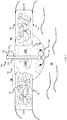
- a membrane 10 consisting of membrane tissue 11 is shown to have an inner cavity 20 for preventing fluid contained in the cavity to leak out to the membrane's surroundings 30.
- Membrane 10 has a perforation site 12 extending from a proximal membrane surface 14 to an inner membrane surface 16 of membrane tissue 11.
- Perforation site 12 can be sealed in a fluid-impermeable manner by employing a membrane closure device 100, e.g., as outlined herein below.
- the term "fluid" as used herein may encompass liquid, gas and/or air.
- patch 120 and/or fastener 140 may be permeable to gas and/or air, but liquid-impermeable.
- patch 120 and/or fastener 140 may be semi-impermeable, e.g., permeable to allow fluid to permeate from surroundings 30 into cavity 20 but impermeable for fluid to flow from cavity 20 into surroundings 30.
- patch 120 and/or fastener 140 may be semi-impermeable to liquid and permeable to gas and/or air.
- patch 120 and/or fastener 140 may be semi-impermeable to gas and/or air.
- Membrane closure device 100 comprises a patch delivery mechanism 110 that comprises a tube-shaped body 111 for slidably guiding a patch 120 to perforation site 12 and, further, a fastener delivery mechanism 130 for delivering a fastener 140 to perforation site 12.
- lubricants e.g., oil
- patch 120 and fastener 140 may be employed for sealing perforation site 12.
- patch 120 may be arranged in an expanded configuration (e.g., expanding latitudinally) onto an inner surface 16 of membrane 10 to cover perforation site 12, and fixed in position by a fastener 140 to seal the perforation.
- fastener 140 may be employed to fixedly attach or secure patch 120 in expanded configuration onto a surface of membrane 10 to seal perforation site 12.
- fastener 140 be operative to sealantly secure patch 120 on membrane 10 to seal perforation site 12.
- one or more patches may be sealantly secured onto outer surface 14 and/or inner membrane surface 16 of membrane 10.
- a first patch may be sealantly secured onto inner membrane surface 16 and a second patch may be sealantly secured to outer membrane surface 14.
- a second patch may be sealantly secured to outer membrane surface 14.
- patch 120 comprises a closure sheet 121 that includes, for example, a self-growing sponge, native tissue, living tissue, Polytetrafluorethylen (PTFE), expanded Polytetrafluorethylen (ePTFE) manufactured, e.g., by employing electro-spinning; silicone-based membrane.
- PTFE Polytetrafluorethylen
- ePTFE expanded Polytetrafluorethylen
- silicone-based membrane may for example be coupled to structures consisting of, for example, synthetic polymer material; natural polymer material, metal; and/or any other suitable matter, composition of matter.
- the silicone-based membranes may be treated, e.g., using dip-coating to produce cell-instructive membranes.
- Fastener 140 may comprise, for example, native tissue, a glue and/or sealant such as, for example, a biocompatible adhesive and/or a biocompatible sealant.
- glue that may be employed can include Mussel glue, agarose glue, fibrin glue, platelet rich plasma, thrombin-containing commercial preparations, collagen, collagen slurry, gelatine sponges, matrigel and/or any other suitable matter.
- the glue and/or sealant may have a growth factor (e.g., activation with soluble epidermal growth factor (EGF) and/or insulin-link growth factor-1 (ILGF-1); and/or comprise a cell instructive scaffold like, for example, a decellularized amniotic membrane.
- a growth factor e.g., activation with soluble epidermal growth factor (EGF) and/or insulin-link growth factor-1 (ILGF-1
- ILGF-1 insulin-link growth factor-1
- the cell instructive scaffold may be glued (e.g., with fibrin), and for example loaded with mixed, soluble TGF-beta or FGF-beta.
- fastener 140 comprises a weld produced, for example, by a laser source.
- patch delivery mechanism 110 comprises a tube-shaped body 111 having a proximal end 112 and a distal end 113 and defining internal to the body a patch delivery passageway.
- Patch delivery mechanism 110 may comprise a patch propelling device 114 that is configured to be employable by the user of membrane closure device 100 for pushing patch 120 through the patch delivery passageway from its proximal 112 to its distal end 113.
- patch propelling device 114 may comprise an elongate body 115 that can be introduced into tube-shaped body 111 and which is long enough to protrude out of the distal end of tube-shaped body 111.
- patch propelling device 114 further comprises an actuation mechanism 116 comprising, e.g., a push button 118 and an energy storage device 119 (e.g., a mechanical energy storage device such as a compression spring) for retaining elongate body 115, and hence patch 120, by default in a retracted position so that patch is retained inside tube-shaped body 111.
- an energy storage device 119 e.g., a mechanical energy storage device such as a compression spring
- Energy storage device 119 is arranged and configured to retain push button 118 and hence, elongate body 115 and patch 120 thereto, by default, in the retracted position.
- energy storage device 119 may be arranged between proximal shoulders of tube-shaped body 111 and shoulders of push button 118.
- patch propelling device 114 may employ additional or alternative mechanisms for retaining patch 120 by default in the retracted position and for actuating delivery of patch 120 to perforation site 12.
- Patch propelling device 114 may comprise, for example, electronic, magnetic, pneumatic, hydraulic and/or any other suitable mechanism.
- elongate body 115 advances and pushes patch 120 out of tube-shaped body 111 so that patch 120 protrudes out of the tube-shaped body's distal end 113.
- patch 120 is in a narrow configuration.
- Patch 120 in the narrow configuration is schematically and exemplarily shown in FIGs. 2A and 2B in the patch-delivery passageway of tube-shaped body 111, at its distal end 113. Once patch 120 is pushed out and no longer confined within the patch delivery passageway running along tube-shaped body 111, the patch may assume the expanded configuration.
- patch delivery mechanism may employ additional and/or alternative handle mechanisms for manually, automatically or semi-automatically propelling patch 120 including, for example, rotary knobs, levers, and/or handles.
- membrane closure device 100 comprises, in an embodiment, a patch manipulation arrangement, e.g., for pulling patch 120 against inner membrane surface 16 and for preventing patch 120 from falling into cavity 20, e.g., due to gravitation, after exiting distal end 113.
- a patch manipulation arrangement e.g., for pulling patch 120 against inner membrane surface 16 and for preventing patch 120 from falling into cavity 20, e.g., due to gravitation, after exiting distal end 113.
- patch manipulation arrangement may for example comprise a patch retention element 117A that runs within tube-shaped body 111 and terminates in a loop to form-fittingly engages with a wire loop 117B that is affixed to closure sheet 121.
- patch retention element 117A may be suture or wire that can be used for suturing of patch 120 to membrane 10.
- membrane closure device 100 may comprise a patch uncoupling mechanism (not shown) comprising, for example, a cutting element (not shown), for cutting wires 117A and/or 117B open, allowing both patch delivery mechanism 110 and fastener delivery mechanism 130 be removed from perforation site 12.
- Expandable patch 120 (which may be self-expandable) further comprises a support structure 123.
- FIGs. 2E and 2F schematically show different example embodiments of such support structure 123, respectively referenced by alphanumeric designations "123A" and "123B".
- support structure 123 is configured to support closure sheet 121.
- Patch 120 is an umbrella-like device that can be modified from a narrow to an expanded configuration.
- support structure 123 is configured to permit patch 120 to be actuated to automatically expand from a narrow configuration to an expanded configuration.
- Expandable patch 120 may assume the expanded configuration after being propelled (e.g., pushed and/or pulled) through tube-shaped body 111 in the narrow configuration and after exiting distal end 113 for closing perforation site 12
- support structure 123 stores more mechanical energy in the folded or narrow configuration than in the expanded configuration. Accordingly, once support structure 123 is no longer confined within the patch delivery passageway running along tube-shaped body 111, support structure 123 may attain the expanded configuration.
- support structure 123 may have to be actuated to obtain the expanded configuration.
- support structure 123 may be made of a shape memory material such as nitinol, and can have a low temperature martensite state, with a martensite transition temperature below body temperature, and a comparatively high temperature austenite state at or above body temperature. Below body temperature, support structure 123 may be in its martensitic state, which is relatively soft, plastic, and easy to shape. In its austenite state, support structure 123 may assume a memorized harder material state in which support structure 123 is more difficult to deform than in the martensitic state.
- the materials employed for producing support structure 123 may be subjected to temperature-based shape-setting. Heating of closure sheet 121 to above body temperature where it may assume its austenite state with its memorized harder material state may in some embodiments be employed including, for example, electric charge/current flowing via a wire/electric-circuit (not shown) (possibly made of copper) or by other means such as laser light propagating via tube-shaped body 111.
- support structure 123 when in the expanded configuration, may be resistant to bending forces of, for example, at least 1 Newton, 2 Newton, 5 Newton, or at least 10 Newton.
- the support structure 123 urges closure sheet 121 to unfold.
- closure sheet 121 may be affixed to support structure 123.
- support structure 123 may be embedded (partially or fully) in closure sheet 121, glued to closure sheet 121, and/or otherwise affixed to closure sheet 121.
- closure sheet 121 in the expanded configuration, closure sheet 121 may be stretchably coupled to support structure 123.
- support structure 123 comprises struts that may for example be made of wires or coils.
- support structure 123A may for example comprise at least two wires 124A and 124B that assume, in the expanded configuration, an S-shaped form.
- the at least two S-shaped wires 124A and 124B may be rotated relative to each other at their midpoints 125 such that the arcuate portions of the S-shaped wires complement a circular-like strut portion running along the outer edge of closure sheet 121.
- a support structure 123 may comprise wires that assume in the expanded configuration, T-shaped, U-shaped, C-shaped, longitudinal wires and/or any other desired form.
- support structure 123B may comprise wires delineating in the expanded configuration the shape of a plurality of petals or lobes 126.
- a petal may assume, in the extended configuration, any polygonal shape and therefore have curved and/or straight vertices and/or edges.
- a petal 126 can have a triangular or substantially triangular shape.
- a wire of support structure 123B may delineate a curve resembling the shape of petalled flower or have a "Shamrock-like" shape.
- additional or alternative approaches or mathematical formulas can be employed to arrive at a support structure 123B delineating, e.g., a petalled contour or curve as exemplarily shown in FIG. 2F , and that the number of petals or lobes shown in FIG. 2F should by no means be construed in a limiting manner.
- a petal or lobe-shaped geometry having the form of a petal 126 may be (virtually) rotated around midpoint 125 for constructing a petalled flower structure.
- a lobe 126 which may be made of a wire, may have the measures (in millimeters) as exemplarily indicated in FIG. 2G .
- Each lobe 126 may comprise two radial portions 30A and 30B virtually originating from midpoint 125 and terminating in a distal convex curve 32A having a radius R.
- a lobe 126 may comprise a convex curve 32B that is proximal to midpoint 125.
- two neighboring lobes 126 may be coupled with each other at adjacent radial portions 30.
- adjacent radiation portions 30 of two neighboring lobes 126 may abut against each other, yet be detached from one another.
- At least one lobe 126 of support structure 123B may comprise coupling elements 127, e.g., for coupling support structure 123B with patch retention element 117A, which is exemplified and schematically illustrated in FIGs. 6A and 6B .
- coupling element 127 may be located proximal to geometric midpoint 125 of support structure 123B.
- lobe 126 may comprise a base 128 that is proximal to midpoint 125.
- base 128 may comprise coupling element 127.
- two coupling elements 127 of respective lobes 126 may be located opposite each other.
- a coupling element 127 may comprise an eyelet, a hook and/or any other suitable configuration to enable the coupling of support structure 123B, and thus of patch 120, with elongate body 115 of patch propelling device 114.
- two lobes 126 that are located opposite each other may each include a coupling element 127.
- the number of lobes 126 is even, only every second lobes 126 may comprise a coupling element 127.
- lobes 126 may have a substantially symmetrical geometry, e.g., as shown in FIGs. 2F and 2G . In some other embodiments, lobes 126 may have a non-symmetrical geometry (not shown).
- support structure 123 may be manufactured, for example, from a sheet of shape memory alloy (e.g., Nitinol) by employing laser-cutting technologies, and/or by welding and/or braiding of wires.
- Support structure 123 may be, in some embodiments, basket-like shaped.
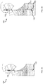
- FIGs. 3A and 3B schematically show a method of using the membrane closure device, according to some embodiments. More specifically, an exemplary in-vitro deployment of patch 120 by the user is schematically illustrated.
- FIG. 3A shows patch 120 in tube-shaped body 111 in the folded configuration
- FIG. 3B shows patch 120 in the expanded configuration.
- patch 120 may have, in the expanded configuration, a concave surface 122 facing inner membrane surface 16.
- the patch's concave surface 122 may facilitate the gathering or holding of glue and/or sealant 140 by closure sheet 121, as is shown schematically in FIG. 1 , and prevent the glue and/or sealant 140 to spill into cavity 20.
- patch 120 may be pulled or held against inner membrane surface 16 circumferencing perforation site 12 for up to 5, 10, 20, 30 or 40 seconds to ensure that the patch is sealantly secured to membrane 10.
- patch retention element 117A may be uncoupled (e.g., cut or released) by operably employing the patch uncoupling mechanism (not shown).
- Patch retention element 117A and wire 117B can be biocompatible and, optionally, biodegradable and/or bioabsorbable.
- membrane closure device 100 comprises a fastener delivery mechanism 130 for delivering a fastener 140 to perforation site 12.
- the fastener delivery mechanism may be manually, automatically or semi-automatically operable.
- a fastener delivery mechanism may be a device that is separate and independently operable from a patch propelling device. In some other embodiments, a fastener delivery mechanism may be integral to a patch propelling device. Although the discussion that follows with respect to the accompanying figures refers to embodiments where a fastener delivery mechanism is integral to a patch propelling device, this should by no means be construed limiting.
- fastener delivery mechanism 130 is configured to enable controllably delivering glue 140, e.g., once patch 120 is deployed at perforation site 12 and, optionally, after it assumed the expanded configuration, for securing patch 120 with the delivered glue 140 to membrane 10.
- fastener delivery mechanism 130 may comprise a glue injection mechanism (not shown).
- glue injection mechanism may comprise a cavity defining internal to elongate body 115 a fastener-delivery passageway that is configured to receive glue 140.
- the glue injection mechanism may further comprise a plunger (not shown) that is provided on the front end thereof with a piston that is slidably movable within the cavities of elongate body 115 for pressing glue 140 out of the fastener-delivery passageway.
- a plunger (not shown) that is provided on the front end thereof with a piston that is slidably movable within the cavities of elongate body 115 for pressing glue 140 out of the fastener-delivery passageway.
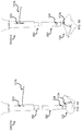
- a fastener-delivery mechanism 330 may have a Y-shaped or bifurcated configuration and may comprise at its bifurcated distal end portions a plurality of barrels (e.g., barrels 331A and 331B ) of a glue injection mechanism (not shown).
- the plurality of barrels may converge to a shared elongate body portion 350 where they are in separate fluid communication with a plurality of fastener-delivery passageways (e.g., passageways 341A and 341B) running along elongate body portion 350 for the separate delivery and, optionally, mixing, of a corresponding plurality of glue compositions of matters (e.g., two glue components).
- the glue injection mechanism can for example comprise, analogous to the embodiments discussed in FIGs.
- a plurality of plungers that are each provided on the front end thereof with a piston (not shown).
- the piston can be slidably movable within the cavities of elongate body of barrels 331A and 331B for pressing glue 140 out of the fastener-delivery passageways.
- fastener delivery mechanism 330 may also function as a patch propelling device 314.
- Patch propelling device 314 may for example be slidably insertable into tube-shaped body 110 for pushing patch 120 outside the distal end of tube-shaped body 111.
- fastener delivery mechanism 330 may comprise a mixer 360 operative to mix two or more adhesive-components with each other for producing an adhesive.
- elongate body 350 may terminate in mixer 360.
- mixer 360 may be implemented as a static or dynamic mixer.
- Mixer 360 may for example comprise a mixing body 361 defining therein a mixing cavity 362. Fins 363 may protrude inwardly into mixing cavity 362 for the mixing of different adhesive matter of composition. In an embodiment, fins 363 are alternatingly arranged opposite each other along the longitudinal axis of mixing body 361. In an embodiment, fins 363 are arranged in a screw-like progression along the tube-shaped mixing body.
- the patch manipulation arrangement of membrane closure device 100 may for example comprise a patch retention element 117A that runs within tube-shaped body 111 and terminates at its distal end that is releasably coupled with patch 120.
- patch retention element 117A may be rod (not shown) that form-fittingly engages with a looped wire or thread 117B that is affixed to patch 120, like a latch or plunger.
- patch retention element 117A may comprise a wire or thread that runs within elongate body portion 350 and exit therefrom via a distal slit 334 for holding patch 120, and may further comprise a rod that is releasably coupled with a looped portion of the wire.
- a proximal end of patch retention element 117A may protrude from fastener-delivery passageway, e.g., via a proximal slit 333, to allow the user to hold it for manipulation of the distal end of patch retention element 117A.
- FIG. 6A schematically shows patch 120 in a retained state, e.g., attached to patch retention element 117A.
- FIG. 6B schematically shows patch 120 in an uncoupled or released state from patch retention element 117A.
- patch 120 may be released by lifting the rod, exemplarily causing the thread to uncouple from elongate body portion 350.
- the thread may be released from a form-fitting and/or frictional coupling state from the distal end of elongate body portion 350.
- patch 120 may be coupled to the distal part of elongate portion 350 of fastener delivery mechanism 130.
- elongate portion 350 may be slidable from a retracted to an extended position, e.g., by lifting or lowering of a handle portion of patch retention element 117A.
- the handle portion may be the portion of patch retention element 117A that protrudes out of proximal slit 333.
- Embodiments disclosed herein may be combined with additional wound closure techniques including, for example, cross-linking technologies and/or membrane healing through biological stimulation.
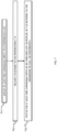
- a method for closing a perforated membrane comprises, in an embodiment, deploy at least one expandable patch to a perforation site.
- deploying the at least one expandable patch may include pulling or pushing the patch against the membrane surface to which the patch shall be affixed.
- patch 120 may be pulled in proximal direction towards the inner surface.
- the method may further include deliver a fastener to the perforation site.
- the method may include fastening the at least one expandable patch in an expanded configuration, by the fastener, to the membrane to seal the perforation.
- FIGs. 8A to 8D exemplarily show images of an example implementation of a membrane closure device. More specifically, FIG. 8A exemplarily shows an image of the elongate body or pushing cylinder of a patch propelling device responsible of pushing the patch out and retaining it for its positioning onto the uterine wall. FIG. 8B exemplarily shows an image of the membrane closure with the patch loaded inside thereof. FIG. 8C is an image exemplarily showing a more detailed view of the pushing, inner cylinder with the wire retaining the patch when deployed and an inner compartment for glue injection. FIG. 8D exemplarily shows that the transparent appearance of the patch in the folded state is due to the employment of oil that was necessary to load the patch into the tube.
- FIGs. 9A to 9F show images of another example implementation of a membrane closure device. More specifically, FIG. 9A shows an image of an exemplary inner cylinder responsible for pushing the patch out and retaining it for its positioning onto the uterine wall.
- FIG. 9B is an image exemplarily showing an image of two smaller tubes that extend throughout the whole construct of the pushing cylinder to deliver a sealant composed of two components.
- FIGs. 9C and 9D are image exemplarily showing the membrane closure device with the patch attached to it via a suture wire loop and retained by a wire controlled at the top here in its closed state.
- FIGs. 9E-9F exemplarily shows this same wire in its open state (patch retention element 117A is uncoupled from wire loop 117B ) for releasing the patch.
- FIGs. 10A and 10B show images of exemplary in-vitro application of the membrane closure device shown in FIGs. 8A to 8D . More specifically, FIGs. 10A and 10B show the deployment of the patch in a wet container.
- FIG. 10C and 10D show different views of the patch affixed to a wet surface with Agarose glue.
- FIGs. 8A to 10D fitted perfectly to the instruments used in clinics for fetoscopy as tested directly on catheters provided by the obstetric department.
- a metallic mold for strict reproducible receptor fabrication was produced and a series of umbrellas were electrospun. Their compatibility to the membrane closure devices was verified by simple insertion into it and its deployment tested in water.
- a test of feasibility included injecting fibrin glue through the two-chamber syringe into the concave surface of the patch. The reception capacity was confirmed by this experiment.
- a nitinol umbrella backbone was manufactured by MeKoTM .
- the nitinol umbrella backbone was embedded into a silicone sheet (the closure sheet).
- the nitinol umbrella backbone could be coated by the electro-spun membrane.
- Example 1 includes a membrane closure device for closing a perforation in a membrane, comprising: a patch delivery mechanism for guiding at least one expandable patch to a perforation site of a membrane; and a fastener delivery mechanism for delivering a fastener to the perforation site and for fastening the at least one expandable patch by the fastener to the membrane to seal the perforation in the membrane by the at least one expandable patch.
- Example 2 includes the subject matter of example 1 and, optionally, at least one tube or tube-shaped body having a distal and a proximal end for delivering the at least one expandable patch in a folded configuration via the tube from the distal to the proximal end for attaching the at least one expandable patch in an expanded configuration to an inner surface of the membrane.
- Example 3 includes the subject matter of example 1 or 2 and, optionally, wherein the at least one expandable patch is a self-expandable patch.
- Example 4 includes the subject matter of example 3 and, optionally, wherein the self-expandable patch is an umbrella-like device comprising struts and a closure sheet affixed to the struts.
- the self-expandable patch is an umbrella-like device comprising struts and a closure sheet affixed to the struts.
- Example 5 includes the subject matter of example 4 and, optionally, wherein the struts comprise at least two S-shaped wires.
- Example 6 includes the subject matter of example 5 and, optionally, wherein the struts comprise shape-memory material composed of, for example, Nitinol.
- Example 7 includes the subject matter of any one of examples 1 to 6 and, optionally, wherein the at least one expandable patch, in the expanded configuration, has a concave surface facing the membrane for the reception of glue.
- Example 8 includes the subject matter of any one of examples 2 to 7 and, optionally, wherein the fastener delivery mechanism comprises the at least one tube for delivering the fastener to the perforation site.
- Example 9 includes the subject matter of any one of the examples 2 to 7 and, optionally, wherein the fastener delivery mechanism comprises at least one other tube, different from the at least one tube, for delivering the fastener to the perforation site.
- Example 10 includes the subject matter of any one of the examples 1 to 9 and, optionally, wherein the fastener comprises any one of the following: biocompatible adhesive, biocompatible sealant, sealant-inducing material, and/or weld.
- Example 11 includes the subject matter of any one of the examples 1 to 10 and, optionally, wherein the fastener delivery mechanism comprises an energy source such as, for example, a laser source.
- the fastener delivery mechanism comprises an energy source such as, for example, a laser source.
- Example 12 includes the subject matter of any one of the examples 1 to 11 and, optionally, wherein the fastener delivery mechanism comprises an adhesive mixing chamber.
- Example 13 includes the subject matter of example 12 and, optionally, wherein the adhesive mixing chamber comprises a tube-shaped body and fins, wherein the fins protrude inwardly into the tube-shaped body for the mixing of different adhesive matter of composition.
- Example 14 includes the subject matter of example 13 and, optionally, wherein the fins are alternatingly arranged opposite each other along the tube's longitudinal axis.
- Example 15 includes the subject matter of examples 13 or 14 and, optionally, wherein the fins are arranged in a screw-like progression along the tube-shaped body.
- Example 16 includes the subject matter of any one of the examples 1 to 15 and, optionally, comprising a patch uncoupling mechanism for releasing or cutting the at least one expandable patch from the membrane closure device following fastening of the at least one expandable patch to the inner membrane surface of the perforation site of the membrane.
- Example 17 includes the subject matter of any one of the examples 1 to 16 and, optionally, wherein the fastener comprises any one of the following: a growth factor and/or a cell instructive scaffold like, for example, a decellularized amniotic membrane.
- the fastener comprises any one of the following: a growth factor and/or a cell instructive scaffold like, for example, a decellularized amniotic membrane.
- Example 18 includes the membrane closure device according to any of the example 1 to 17 for use in treating a perforation of a fetal membrane, for use in treating a perforation of a vascular membrane, for use in treating a perforation of a cardiovascular membrane and/or for use in treating a tympanic membrane.
- Example 19 includes a method for closing a perforation in a membrane by a membrane closure device, comprising:
- Example 20 includes the subject matter of example 19 and, optionally, operably deploying a plurality of patches.
- each of the verbs, "comprise” “include” and “have”, and conjugates thereof, are used to indicate that the object or objects of the verb are not necessarily a complete listing of components, elements or parts of the subject or subjects of the verb.
- range format is merely for convenience and brevity and should not be construed as an inflexible limitation on the scope of the invention. Accordingly, the description of a range should be considered to have specifically disclosed all the possible subranges as well as individual numerical values within that range. For example, description of a range such as from 1 to 6 should be considered to have specifically disclosed subranges such as from 1 to 3, from 1 to 4, from 1 to 5, from 2 to 4, from 2 to 6, from 3 to 6 etc., as well as individual numbers within that range, for example, 1, 2, 3, 4, 5, and 6. This applies regardless of the breadth of the range.
Landscapes
- Health & Medical Sciences (AREA)
- Life Sciences & Earth Sciences (AREA)
- Surgery (AREA)
- Heart & Thoracic Surgery (AREA)
- Engineering & Computer Science (AREA)
- Biomedical Technology (AREA)
- Nuclear Medicine, Radiotherapy & Molecular Imaging (AREA)
- Medical Informatics (AREA)
- Molecular Biology (AREA)
- Animal Behavior & Ethology (AREA)
- General Health & Medical Sciences (AREA)
- Public Health (AREA)
- Veterinary Medicine (AREA)
- Cardiology (AREA)
- Surgical Instruments (AREA)
Priority Applications (7)
| Application Number | Priority Date | Filing Date | Title |
|---|---|---|---|
| CA3052225A CA3052225A1 (fr) | 2017-02-06 | 2018-02-05 | Dispositif et methode pour sceller une membrane |
| JP2019542434A JP2020505181A (ja) | 2017-02-06 | 2018-02-05 | 膜を密閉するためのデバイス及び方法 |
| EP18705560.3A EP3576637B1 (fr) | 2017-02-06 | 2018-02-05 | Dispositif pour sceller une membrane |
| CN201880018772.4A CN110446467A (zh) | 2017-02-06 | 2018-02-05 | 用于密封膜的装置和方法 |
| BR112019016097A BR112019016097A2 (pt) | 2017-02-06 | 2018-02-05 | dispositivo e método para vedar uma membrana |
| US16/483,445 US20200008788A1 (en) | 2017-02-06 | 2018-02-05 | Device and method for sealing a membrane |
| PCT/EP2018/052765 WO2018141951A1 (fr) | 2017-02-06 | 2018-02-05 | Dispositif et méthode pour sceller une membrane |
Applications Claiming Priority (1)
| Application Number | Priority Date | Filing Date | Title |
|---|---|---|---|
| EP16191271 | 2016-09-29 |
Publications (1)
| Publication Number | Publication Date |
|---|---|
| EP3300669A1 true EP3300669A1 (fr) | 2018-04-04 |
Family
ID=57042700
Family Applications (1)
| Application Number | Title | Priority Date | Filing Date |
|---|---|---|---|
| EP17154743.3A Withdrawn EP3300669A1 (fr) | 2016-09-29 | 2017-02-06 | Dispositif et procédé de fermeture étanche d'une membrane |
Country Status (1)
| Country | Link |
|---|---|
| EP (1) | EP3300669A1 (fr) |
Cited By (6)
| Publication number | Priority date | Publication date | Assignee | Title |
|---|---|---|---|---|
| WO2018141951A1 (fr) * | 2017-02-06 | 2018-08-09 | Universitaet Zürich | Dispositif et méthode pour sceller une membrane |
| WO2019133894A1 (fr) * | 2017-12-29 | 2019-07-04 | Tricol Biomedical, Inc. | Systèmes de pose pour prise en charge des hémorragies gastro-intestinales |
| US11660236B2 (en) | 2017-12-29 | 2023-05-30 | Tricol Biomedical, Inc. | Delivery systems for control of bleeding in transurethral prostatectomy |
| US12156791B2 (en) | 2017-12-29 | 2024-12-03 | Tricol Biomedical, Inc. | Chitosan dressing for control of bleeding in transurethral prostatectomy |
| EP4422511A4 (fr) * | 2021-10-28 | 2025-07-16 | Joseph Choate Burkett | Appareil et méthodes de réparation de tissu de site de biopsie |
| US12616771B2 (en) | 2017-12-29 | 2026-05-05 | Tricol Biomedical, Inc. | Tissue adherent chitosan material that resists dissolution |
Citations (9)
| Publication number | Priority date | Publication date | Assignee | Title |
|---|---|---|---|---|
| EP1595504A1 (fr) * | 2004-05-12 | 2005-11-16 | Medtronic Vascular, Inc. | Patch pour défauts cardio-vasculaires |
| US20080058710A1 (en) * | 2006-08-15 | 2008-03-06 | Wilk Peter J | Surgical kit, closure device, and associated method |
| US20100191295A1 (en) * | 2009-01-23 | 2010-07-29 | Warsaw Orthopedic, Inc. | Annulus repair system |
| DE202010011724U1 (de) * | 2010-08-23 | 2010-11-04 | Osypka Ag | Verschlusssystem für Öffnungen oder Defekte in Organen |
| WO2011057282A2 (fr) * | 2009-11-09 | 2011-05-12 | Cardiovascular Technologies, Inc. | Dispositifs de fermeture de tissu, dispositif et systèmes pour leur pose, coffrets et méthodes pour ceux-ci |
| EP2353513A1 (fr) * | 2010-02-08 | 2011-08-10 | Tyco Healthcare Group LP | Patch à vide pour la fermeture rapide des plaies |
| WO2011137224A1 (fr) * | 2010-04-29 | 2011-11-03 | Danny Azriel Sherwinter | Systèmes et procédés pour faciliter la fermeture d'ouvertures corporelles |
| WO2013009872A1 (fr) * | 2011-07-11 | 2013-01-17 | The Regents Of The University Of Michigan | Dispositif multimodalité d'occlusion de l'appendice de l'auricule gauche |
| WO2014150154A1 (fr) * | 2013-03-15 | 2014-09-25 | Essential Medical, Inc. | Dispositifs de fermeture vasculaire et procédés d'utilisation |
-
2017
- 2017-02-06 EP EP17154743.3A patent/EP3300669A1/fr not_active Withdrawn
Patent Citations (9)
| Publication number | Priority date | Publication date | Assignee | Title |
|---|---|---|---|---|
| EP1595504A1 (fr) * | 2004-05-12 | 2005-11-16 | Medtronic Vascular, Inc. | Patch pour défauts cardio-vasculaires |
| US20080058710A1 (en) * | 2006-08-15 | 2008-03-06 | Wilk Peter J | Surgical kit, closure device, and associated method |
| US20100191295A1 (en) * | 2009-01-23 | 2010-07-29 | Warsaw Orthopedic, Inc. | Annulus repair system |
| WO2011057282A2 (fr) * | 2009-11-09 | 2011-05-12 | Cardiovascular Technologies, Inc. | Dispositifs de fermeture de tissu, dispositif et systèmes pour leur pose, coffrets et méthodes pour ceux-ci |
| EP2353513A1 (fr) * | 2010-02-08 | 2011-08-10 | Tyco Healthcare Group LP | Patch à vide pour la fermeture rapide des plaies |
| WO2011137224A1 (fr) * | 2010-04-29 | 2011-11-03 | Danny Azriel Sherwinter | Systèmes et procédés pour faciliter la fermeture d'ouvertures corporelles |
| DE202010011724U1 (de) * | 2010-08-23 | 2010-11-04 | Osypka Ag | Verschlusssystem für Öffnungen oder Defekte in Organen |
| WO2013009872A1 (fr) * | 2011-07-11 | 2013-01-17 | The Regents Of The University Of Michigan | Dispositif multimodalité d'occlusion de l'appendice de l'auricule gauche |
| WO2014150154A1 (fr) * | 2013-03-15 | 2014-09-25 | Essential Medical, Inc. | Dispositifs de fermeture vasculaire et procédés d'utilisation |
Non-Patent Citations (3)
| Title |
|---|
| ACTA BIOMATERIALIA, vol. 8, 2012, pages 4365 - 70 |
| BILIC ET AL., AMERICAN JOURNAL OF OBSTETRICS AND GYNECOLOGY, vol. 202, 2010, pages 85 EL - 9 |
| LEE ET AL., NATURE, vol. 448, 2007, pages 338 - 41 |
Cited By (8)
| Publication number | Priority date | Publication date | Assignee | Title |
|---|---|---|---|---|
| WO2018141951A1 (fr) * | 2017-02-06 | 2018-08-09 | Universitaet Zürich | Dispositif et méthode pour sceller une membrane |
| WO2019133894A1 (fr) * | 2017-12-29 | 2019-07-04 | Tricol Biomedical, Inc. | Systèmes de pose pour prise en charge des hémorragies gastro-intestinales |
| US11564673B2 (en) | 2017-12-29 | 2023-01-31 | Tricol Biomedical, Inc. | Delivery systems for control of gastrointestinal bleeding |
| US11660236B2 (en) | 2017-12-29 | 2023-05-30 | Tricol Biomedical, Inc. | Delivery systems for control of bleeding in transurethral prostatectomy |
| US12156791B2 (en) | 2017-12-29 | 2024-12-03 | Tricol Biomedical, Inc. | Chitosan dressing for control of bleeding in transurethral prostatectomy |
| US12508171B2 (en) | 2017-12-29 | 2025-12-30 | Tricol Biomedical, Inc. | Delivery systems for control of bleeding in transurethral prostatectomy |
| US12616771B2 (en) | 2017-12-29 | 2026-05-05 | Tricol Biomedical, Inc. | Tissue adherent chitosan material that resists dissolution |
| EP4422511A4 (fr) * | 2021-10-28 | 2025-07-16 | Joseph Choate Burkett | Appareil et méthodes de réparation de tissu de site de biopsie |
Similar Documents
| Publication | Publication Date | Title |
|---|---|---|
| US20230190272A1 (en) | Complex surgical device for carrying out and protecting an anastomosis | |
| ES2353260T3 (es) | Dispositivos para el cierre de heridas. | |
| US8480693B2 (en) | Method and device for temporary emergency vessel anastomoses | |
| EP3193738B1 (fr) | Dispositif de fermeture de plaie bioabsorbable | |
| EP3576637B1 (fr) | Dispositif pour sceller une membrane | |
| US20070203517A1 (en) | Transgastric surgical devices and procedures | |
| CN101431948A (zh) | 进入与封闭装置和方法 | |
| CN101524292A (zh) | 经腔组织标记物 | |
| CA2551573A1 (fr) | Dispositif de suture pour un dispositif implantable | |
| US10299828B2 (en) | Anchor delivery system and method | |
| US20150011925A1 (en) | Method and device for temporary emergency vessel anastomoses | |
| US9775598B2 (en) | Anchored suture line, device and method for surgical suturing | |
| JP2016526432A (ja) | 開放可能な流路を伴う閉塞器具 | |
| EP1429661B1 (fr) | Dispositif pour l'obturation de vaisseau corporel perfore | |
| US20190290475A1 (en) | Reversible hysteroscopic sterilization | |
| US9839415B2 (en) | Apex closure device | |
| WO2019037505A1 (fr) | Écarteur d'incision chirurgicale | |
| JP7843307B2 (ja) | 組織開口部のための閉鎖装置 | |
| US20140155934A1 (en) | Degradable expanding closure plug | |
| US20130304118A1 (en) | Devices and Methods for Vascular Closure | |
| US20180055497A1 (en) | Vascular closure device | |
| WO2024105666A1 (fr) | Dispositif de pose de patches chirurgicaux pendant une chirurgie minimalement invasive |
Legal Events
| Date | Code | Title | Description |
|---|---|---|---|
| PUAI | Public reference made under article 153(3) epc to a published international application that has entered the european phase |
Free format text: ORIGINAL CODE: 0009012 |
|
| AK | Designated contracting states |
Kind code of ref document: A1 Designated state(s): AL AT BE BG CH CY CZ DE DK EE ES FI FR GB GR HR HU IE IS IT LI LT LU LV MC MK MT NL NO PL PT RO RS SE SI SK SM TR |
|
| AX | Request for extension of the european patent |
Extension state: BA ME |
|
| STAA | Information on the status of an ep patent application or granted ep patent |
Free format text: STATUS: THE APPLICATION IS DEEMED TO BE WITHDRAWN |
|
| 18D | Application deemed to be withdrawn |
Effective date: 20181005 |