EP3300749A1 - Pompe à sang magnétisée passivement - Google Patents
Pompe à sang magnétisée passivement Download PDFInfo
- Publication number
- EP3300749A1 EP3300749A1 EP16191579.8A EP16191579A EP3300749A1 EP 3300749 A1 EP3300749 A1 EP 3300749A1 EP 16191579 A EP16191579 A EP 16191579A EP 3300749 A1 EP3300749 A1 EP 3300749A1
- Authority
- EP
- European Patent Office
- Prior art keywords
- rotor
- bearing
- blood pump
- inlet
- magnets
- Prior art date
- Legal status (The legal status is an assumption and is not a legal conclusion. Google has not performed a legal analysis and makes no representation as to the accuracy of the status listed.)
- Withdrawn
Links
- 239000008280 blood Substances 0.000 title claims abstract description 105
- 210000004369 blood Anatomy 0.000 title claims abstract description 105
- 230000005291 magnetic effect Effects 0.000 title abstract description 34
- 239000012530 fluid Substances 0.000 claims abstract description 15
- 230000006641 stabilisation Effects 0.000 claims description 8
- 238000011105 stabilization Methods 0.000 claims description 8
- 229910010293 ceramic material Inorganic materials 0.000 claims description 4
- 239000011248 coating agent Substances 0.000 claims description 4
- 238000000576 coating method Methods 0.000 claims description 4
- 241001465754 Metazoa Species 0.000 claims description 3
- 230000005520 electrodynamics Effects 0.000 claims description 3
- 235000015095 lager Nutrition 0.000 description 29
- 239000000463 material Substances 0.000 description 7
- 238000011161 development Methods 0.000 description 5
- 230000018109 developmental process Effects 0.000 description 5
- 210000004204 blood vessel Anatomy 0.000 description 3
- 239000000919 ceramic Substances 0.000 description 3
- 230000017531 blood circulation Effects 0.000 description 2
- 238000007667 floating Methods 0.000 description 2
- 239000002655 kraft paper Substances 0.000 description 2
- 239000000696 magnetic material Substances 0.000 description 2
- OKTJSMMVPCPJKN-UHFFFAOYSA-N Carbon Chemical compound [C] OKTJSMMVPCPJKN-UHFFFAOYSA-N 0.000 description 1
- 101100390736 Danio rerio fign gene Proteins 0.000 description 1
- 101100390738 Mus musculus Fign gene Proteins 0.000 description 1
- 239000011149 active material Substances 0.000 description 1
- 230000006978 adaptation Effects 0.000 description 1
- 229910052799 carbon Inorganic materials 0.000 description 1
- 239000013065 commercial product Substances 0.000 description 1
- 238000004891 communication Methods 0.000 description 1
- 238000010276 construction Methods 0.000 description 1
- 230000001419 dependent effect Effects 0.000 description 1
- 239000010432 diamond Substances 0.000 description 1
- 229910003460 diamond Inorganic materials 0.000 description 1
- 230000000694 effects Effects 0.000 description 1
- 238000005516 engineering process Methods 0.000 description 1
- 230000002349 favourable effect Effects 0.000 description 1
- 239000010437 gem Substances 0.000 description 1
- 210000005003 heart tissue Anatomy 0.000 description 1
- 238000009434 installation Methods 0.000 description 1
- 230000003993 interaction Effects 0.000 description 1
- 238000012423 maintenance Methods 0.000 description 1
- 239000004033 plastic Substances 0.000 description 1
- 229920003023 plastic Polymers 0.000 description 1
- 239000002243 precursor Substances 0.000 description 1
- 230000036316 preload Effects 0.000 description 1
- 230000001737 promoting effect Effects 0.000 description 1
- 230000001105 regulatory effect Effects 0.000 description 1
- 239000010979 ruby Substances 0.000 description 1
- 229910001750 ruby Inorganic materials 0.000 description 1
- 229910052594 sapphire Inorganic materials 0.000 description 1
- 239000010980 sapphire Substances 0.000 description 1
- 230000000087 stabilizing effect Effects 0.000 description 1
- 238000011144 upstream manufacturing Methods 0.000 description 1
- 208000008918 voyeurism Diseases 0.000 description 1
Images


Classifications
-
- A—HUMAN NECESSITIES
- A61—MEDICAL OR VETERINARY SCIENCE; HYGIENE
- A61M—DEVICES FOR INTRODUCING MEDIA INTO, OR ONTO, THE BODY; DEVICES FOR TRANSDUCING BODY MEDIA OR FOR TAKING MEDIA FROM THE BODY; DEVICES FOR PRODUCING OR ENDING SLEEP OR STUPOR
- A61M60/00—Blood pumps; Devices for mechanical circulatory actuation; Balloon pumps for circulatory assistance
- A61M60/80—Constructional details other than related to driving
- A61M60/802—Constructional details other than related to driving of non-positive displacement blood pumps
- A61M60/818—Bearings
- A61M60/82—Magnetic bearings
-
- A—HUMAN NECESSITIES
- A61—MEDICAL OR VETERINARY SCIENCE; HYGIENE
- A61M—DEVICES FOR INTRODUCING MEDIA INTO, OR ONTO, THE BODY; DEVICES FOR TRANSDUCING BODY MEDIA OR FOR TAKING MEDIA FROM THE BODY; DEVICES FOR PRODUCING OR ENDING SLEEP OR STUPOR
- A61M60/00—Blood pumps; Devices for mechanical circulatory actuation; Balloon pumps for circulatory assistance
- A61M60/80—Constructional details other than related to driving
- A61M60/802—Constructional details other than related to driving of non-positive displacement blood pumps
- A61M60/81—Pump housings
-
- A—HUMAN NECESSITIES
- A61—MEDICAL OR VETERINARY SCIENCE; HYGIENE
- A61M—DEVICES FOR INTRODUCING MEDIA INTO, OR ONTO, THE BODY; DEVICES FOR TRANSDUCING BODY MEDIA OR FOR TAKING MEDIA FROM THE BODY; DEVICES FOR PRODUCING OR ENDING SLEEP OR STUPOR
- A61M60/00—Blood pumps; Devices for mechanical circulatory actuation; Balloon pumps for circulatory assistance
- A61M60/10—Location thereof with respect to the patient's body
- A61M60/122—Implantable pumps or pumping devices, i.e. the blood being pumped inside the patient's body
-
- A—HUMAN NECESSITIES
- A61—MEDICAL OR VETERINARY SCIENCE; HYGIENE
- A61M—DEVICES FOR INTRODUCING MEDIA INTO, OR ONTO, THE BODY; DEVICES FOR TRANSDUCING BODY MEDIA OR FOR TAKING MEDIA FROM THE BODY; DEVICES FOR PRODUCING OR ENDING SLEEP OR STUPOR
- A61M60/00—Blood pumps; Devices for mechanical circulatory actuation; Balloon pumps for circulatory assistance
- A61M60/20—Type thereof
- A61M60/205—Non-positive displacement blood pumps
- A61M60/216—Non-positive displacement blood pumps including a rotating member acting on the blood, e.g. impeller
-
- A—HUMAN NECESSITIES
- A61—MEDICAL OR VETERINARY SCIENCE; HYGIENE
- A61M—DEVICES FOR INTRODUCING MEDIA INTO, OR ONTO, THE BODY; DEVICES FOR TRANSDUCING BODY MEDIA OR FOR TAKING MEDIA FROM THE BODY; DEVICES FOR PRODUCING OR ENDING SLEEP OR STUPOR
- A61M60/00—Blood pumps; Devices for mechanical circulatory actuation; Balloon pumps for circulatory assistance
- A61M60/40—Details relating to driving
- A61M60/403—Details relating to driving for non-positive displacement blood pumps
- A61M60/422—Details relating to driving for non-positive displacement blood pumps the force acting on the blood contacting member being electromagnetic, e.g. using canned motor pumps
Definitions
- a blood pump comprising an inlet, an outlet and a rotor for conveying fluid, in particular blood, from the inlet to the outlet, the rotor being radially passively magnetically mounted inside the blood pump and repelled or attracted axially in one direction at least passively becomes.
- the blood pump is configured such that when the rotor rotates fluidly, the axial thrust of the rotor acts against the magnetic attraction acting axially in the direction of the outlet.
- the drive of the rotor takes place, for example, contactless by a brushless DC motor.
- a further embodiment provides that the non-contact portion of the bearing of the rotor is purely passively magnetic, that is, that no additional control coils, etc. are necessary for positioning the rotor.
- an electromagnetic and / or electrodynamic device acting on the rotor is provided. This is possible, for example, to further relieve the mechanical bearing in order to keep the rotor as floating or low-force as possible. This can be done for example by appropriate electromagnetic devices or control coils.
- a further development provides that the rotor, in particular for axial bearing, is additionally supported by a mechanical bearing.
- This mechanical bearing can be designed, in particular, as a contact bearing, in particular as a point or ball bearing.
- a mechanically reliable device is provided, which ensures a stable rotor position, especially at lower speeds.
- the rotor in particular for axial bearing, additionally be supported by a hydrodynamic bearing, which is arranged, for example, in the outlet-side region of the rotor.
- a hydrodynamic bearing which is arranged, for example, in the outlet-side region of the rotor.
- Advantageous examples are hydrodynamic bearings in the form of spiral groove bearings.
- a further embodiment provides that an additional bearing, in particular an axial catch bearing for limiting the axial rotor movement, is provided. This ensures that no “damage” to the rotor blades or blood contact surfaces of the pump occurs when the pump is "sucked” against a heart wall and the resulting very strong axial thrust occurs because the rotor is pulled too strongly in the direction of the inlet.
- an additional bearing in particular an axial catch bearing for limiting the axial rotor movement
- a further development provides that in the area of at least one additional bearing the rotor and / or adjacent parts of the blood pump, in particular with ceramic materials and / or a hard material coating, for example DLC (Diamond-Like Carbon), are reinforced.
- ceramic materials and / or a hard material coating for example DLC (Diamond-Like Carbon)
- Blood pumps according to the above claims are possible for different storage concepts, for example for axial pumps / mixed flow pumps or also radial pumps.
- an axial inflow and delivery can take place through the rotor, and an axial outflow or tangential outflow in the region of the outlet.
- the inlet and outlet are each connectable to human or animal blood vessels to enhance and / or regulate natural blood flow.
- a further embodiment provides that bearing magnets of the rotor for radial and axial stabilization of the rotor within the housing of the Blood pump are provided. This means that rotating rotor bearing magnets are provided with the rotor, which take over the stabilizing and / or centering function for the rotor.
- a further embodiment provides that the bearing magnets of the rotor are arranged on the side facing away from the inlet of the rotor and / or that the bearing magnets are arranged on the inlet side facing.
- the bearing magnets of the rotor are arranged on the side facing away from the inlet of the rotor and / or that the bearing magnets are arranged on the inlet side facing.
- Another embodiment provides that motor coils are provided in the stator of the blood pump and rotor magnets in the rotor, wherein the motor coils are arranged on the side facing the inlet of the rotor and / or on the side facing away from the inlet of the rotor. Also in this way the greatest possible flexibility in the design of the blood pump is guaranteed.
- a further embodiment provides that a mechanical bearing is arranged on the inlet-facing side of the rotor and / or on the side facing away from the inlet of the rotor.
- the rotor may be supported in different ways (preferably counter to the flow direction of the blood flowing in through the inlet), but other arrangements may be provided, for example a two-bearing arrangement in which closure of the inlet is by one in the direction the inlet moving rotor is prevented.
- the rotor is connected in its central region via struts with a mechanical bearing.
- This is suitable, for example, for embodiments in which only one bearing is provided and this bearing is provided on the side of the rotor facing the inlet (but also on the outlet side, the bearing point with struts can be connected to the rotor).
- a further embodiment provides that the blood pump has a stator, wherein this embodiment in the region of a rotation axis of the Rotor bearing magnets (these are preferably in communication with corresponding bearing magnets of the rotating rotor) and wherein the stator in the region of the axis of rotation of the rotor also has a stator, on the tip of a dome of a mechanical bearing is arranged, and in addition rotor magnets of the rotor (preferably in a support disk of the rotor) are arranged and / or arranged with the rotor magnets in operative connection motor coils in the stator on the side facing away from the inlet side of the rotor.
- the blood pump is designed as a radial pump with struts, wherein arranged on a survey of the stator in the region of the axis of rotation of the rotor a standing with struts of the rotor dome of a mechanical bearing and bearing magnets on the one hand stator disposed in the stator On the other hand, are arranged in the rotor bearing magnets, preferably on the side facing away from the inlet of the rotor, and further the rotor additionally rotor magnets on the inlet side facing the rotor, said rotor magnets cooperate with motor coils in the region of the inlet of the blood pump.
- Another embodiment provides that the rotor is passively magnetically attracted.
- the rotor is passively magnetically attracted.
- other configurations can be provided (see figures).
- a further embodiment provides that the radial distance between at least one rotor-side bearing magnet and at least one stator-side bearing magnet is so small that a secure storage is achieved even with the lowest possible volume of magnetically active material.
- the fluid-permeable gap can be ⁇ 50 ⁇ m, for example 100 ⁇ m (see, for example, also US Pat Fig. 4 , Reference 13 in the present patent).
- the gap between the magnetically active parts may be, for example, between 500 .mu.m and 2000 .mu.m, for example 1000 .mu.m, although this need not be an air gap; non-magnetic materials (eg corresponding plastics) may be present in this gap; for details or definitions reference is made to the introduction to the description of this property right).
- a further embodiment provides that the blood pump does not have a precursor wheel upstream of the rotor.
- the blood pump does not have a precursor wheel upstream of the rotor.
- such (structurally simple) embodiment can be selected, in particular if by the magnetic arrangement of the bearing magnets or by a suitable interaction of the motor coils with the is secured to the driving rotor magnet of the rotor within the blood pump.
- a further embodiment provides that the bearing magnets of the rotor are fixed in brackets attached to the rotor main body arms of the rotor, said rotor-side bearing magnets with radially outward of the bearing magnets of the rotor lying bearing magnet of the stator for radial and / or axial stabilization of the rotor within the blood pump interact.
- a further development provides that the motor is designed to drive the rotor as a disk motor.
- Another aspect relates to the placement of permanent magnets in the blades of the rotor. This results in a reduction of the magnetic air gap.
- blades made of magnetic material and / or blades with permanent magnets contained therein are hereby deemed to be disclosed (regardless of which storage mode is provided).
- Fig. 1 shows a blood pump 1 in the area of a camp 3.
- the in Fig. 1 The arrows shown indicate the orientation of the layered magnets; However, this is purely exemplary and without being limited to a resulting magnetic force direction to understand.
- Fig. 1 to see how a part of a rotor 2 in a ring of the bearing 3 is radially held by a radial passive magnetic force and a bias voltage in a desired axial direction can be achieved. Examples of the use of such storage are shown in the following figures.
- Fig. 2 shows such a blood pump 1, in which a rotor 2 is mounted.
- a rotor 2 For this purpose, in the region of the inlet 10 and the outlet 11 respectively held on struts (Vorleitrad or diffuser) 5 bearing 3 (eg according to Fig. 1 ) intended.
- the rotation of the rotor creates a flow (ie a fluid flow) in the direction of the arrow 6.
- the rotor is driven by a motor, not shown here.
- the blood pump 1 thus contains an inlet 10 and an outlet 11, the rotor 2 being designed to convey fluid (in the direction 6) from the inlet to the outlet.
- the rotor 2 is mounted radially passively magnetically within the blood pump 1 and axially attracted (biased) at least passively axially in the direction of the outlet 11, so that the axial thrust of the rotor acts against the acting magnetic bias when the rotor 2 rotates fluidically. That is, the flow is from the inlet 10 to the outlet 11 in the direction 6; the axial thrust of the rotor acts in the opposite direction.
- a mechanical bearing is also shown in the outlet-side region of the rotor, which is present as a contact bearing 4 (here designed as a tip bearing).
- a contact bearing 4 here, for example, at low speeds, an exact rotor positioning or centering at relatively low friction possible.
- part of the rotor or adjacent areas of the blood pump are made of hard materials (eg jewels or ruby, sapphire, diamond, DLC or ceramics) to further minimize friction and increase durability.
- Fig. 3 shows an alternative design of a blood pump.
- an axial inlet 10 is shown.
- an outlet chamber or outlet 11 is shown, which allows a tangential / lateral outflow of blood.
- the rotor 2 is in a bearing 3 (see Fig. 1 Magnetically supported radially and biased axially in one direction. The drive of the rotor is effected without contact by a motor 8.
- Shown is also a fishing camp 9, which prevents jamming or slipping out of the rotor 2 from the blood pump housing out with a suction of the inlet 10 to a heart wall.
- a hydrodynamic bearing 7 is shown at the outlet end of the blood pump.
- This is, for example, a spiral groove bearing, which touches adjacent areas of the housing of the blood pump, for example, at low speeds (in which the hydrodynamic properties are not yet fully effective).
- ceramic and / or DLC materials are provided to reduce friction or increase the life.
- the additional axial thrust of the rotor supports and relieves the hydrodynamic bearing. Also apply to this rotor in the patent claim 1 in submitted form features.
- an axial / Halbaxial- or radial pump is radially passively magnetically supported (possibly with a supporting hydrodynamic component) and also axially given a passive magnetic bias in one direction.
- axial thrust which is dependent on the pressure difference acts.
- a positive axial thrust will always be present in a human circuit;
- the rotor can float without additional bearings.
- the axial bearing is supported by a one-sided mechanical or hydrodynamic bearing.
- An inlet side mechanical safety bearing if the axial thrust becomes too large (during suction on the heart tissue), can be ensured by material combinations (ceramic, hard material coating, eg DLC).
- the magnetic axial preload can also be chosen so strong that even in the worst-case scenarios (suction) a contact on the axial mechanical bearing is present.
- the radial passive magnetic force and the bias in an axial direction can be determined by the in Fig. 1 shown magnet configuration can be achieved.
- the axial bias can also be performed by additional attractive or repulsive magnets.
- the stator is substantially rohrfömig with an inlet 10 and a non-axial outlet 11.
- a bearing 3 is provided, which is designed as a plain bearing, for example as axial or radial bearings.
- the bearing is arranged so that the inflow through the inlet 10 flow loads the bearing on pressure.
- the blades 14 are oriented so that upon a promotional movement of the rotor 2, a pressure relief on the bearing 3 takes place.
- radial and axial stabilization of the rotor within the stator of the blood pump bearing magnets of the rotor 15 and bearing magnets of the stator 16 are provided.
- the bearing magnets of the rotor 15 are attached by means of struts 12 to arms of the rotor.
- the corresponding arms in which the bearing magnets 15 are housed can be circular; individual satellites can also be provided be arranged distributed over the circumference. It can be provided on respective struts Einutzchen and outlet side each such arms.
- An advantage of this arrangement is that (regardless of the blading) a good radial and axial stabilization of the rotor can be achieved within the stator.
- a gap 13 is as small as possible, for example ⁇ 50 ⁇ m, but less than 200 ⁇ m, preferably less than 150 ⁇ m, particularly preferably less than 100 ⁇ m.
- struts 12 which are for example rod-shaped and allow a fluid passage
- the struts 12 that on the one hand in the region of the boom or the bearing magnets 15/16 good stabilization of the rotor 2 is given, on the other hand, a relatively unhindered flow of fluid (preferably Blood) despite the small gap widths 13 is possible.
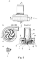
- Fig. 5 shows Fig. 5a a side view, Fig. 5b a cut BB off Fig. 5a, Fig. 5c a section CC- off Fig. 5a such as Fig. 5d a reduced perspective view of the overall pump with inlet 10 and outlet 11; the inlet 10 is adapted for attachment to a cannula or blood vessel, the same applies to the outlet 11) shows a fully implantable blood pump with an intracorporeal radial pump with magnet and motor within a pump housing. In the housing, an axial inlet and a radial outlet is provided.
- the rotor 2 is mounted on a mechanical bearing 4, which is designed as a contact bearing and is designed to be particularly low friction, the material pairing, for example, ceramic materials and / or hard coating, eg DLC contains.
- the part of the rotor which is mounted is connected via struts 12 with the rest of the rotor.
- the rotor is made hollow in regions, that is, it contains oblique / radial conveyor blades, which promote axially axially through the inlet 10 entering fluid radially outward.
- the rotor 2 is designed substantially disc-shaped, wherein the storage is arranged in the lower region and above the responsible for the fluid conveying channels or blades and above (ie in the direction of the inlet) rotor magnets 18 are provided with axially above it (ie even further in the direction of the inlet 10 located) motor coils 17 for driving the rotor 2 located in the stator cooperate.
- This has the Advantage that as few moving elements are provided and only an electromagnetic actuation of the rotor takes place within the housing of the blood pump. This is on the one hand low maintenance and on the other hand, easy to set up.
- rotor-side bearing magnets 15 and stator-side bearing magnets 16 are provided, which are provided for the radial and axial stabilization of the rotor within the housing of the blood pump.
- the bearing is arranged so that at fluid pressure and stationary rotor, the rotor is pressed against the bearing 4; When fluid is conveyed through the rotor 2, there is a pressure relief of the bearing 4.
- the layered structure of the rotor allows a clear and simple structure, with rotor magnets 18 and rotor-side bearing magnets 15 are housed in a cover plate of the rotor and with corresponding stator-side elements (motor coils 17 and stator-side bearing magnet 16) cooperate.
- Fig. 6 shows Fig. 6a a side view, Fig. 6b a cut BB off Fig. 6a, Fig. 6c a section CC- off Fig. 6a such as Fig. 6d a reduced perspective view of the overall pump with inlet 10 and outlet 11; the inlet 10 is designed for attachment to a cannula or a blood vessel, the same applies to the outlet 11) shows a further embodiment, in which an axial inlet 10 and a radial outlet 11 are again shown.
- This is a Halbaxialpumpe with a central stator, in which stator-side bearing magnets 16 are installed and on the top of the dome of a mechanical bearing 4 sits.
- the motor coils 17 are located in the housing, ie, stator side in the blood pump 1; these interact with rotor magnets 18 which are accommodated in the lower part of the rotor 2.
- this rotor 2 may also contain an additional cover disk. It is thus a blood pump 1 with a stator 19, wherein in the region of a rotation axis of the rotor 2 bearing magnets of the stator are arranged and wherein the stator 19 in the region of the axis of rotation of the rotor 2 has a stator, on the top of a dome of a mechanical Bearing is arranged, and in addition rotor magnets 18 of the rotor are preferably arranged in a support disk of the rotor 2 and / or with the rotor magnets in operative connection motor coils 17 are arranged in the stator 19 on the side facing away from the inlet 10 of the rotor 2.
- Fig. 7 shows a further embodiment of a blood pump 1, in which an axial inlet 10 and a radial outlet 11 are given.
- the rotor 2 has rotor magnets 18 on the side facing the inlet, which cooperate with motor coils 17 in the housing of the blood pump 1 for driving the rotor.
- a mechanical bearing 4 is provided in which struts 12, which allow a fluid passage in the direction from the inlet 10 to the outlet 11, are provided and allow additional mechanical support or support of the rotor.
- the bearing technology shown in this patent can be a platform for small, passive rotary blood pumps with high hemocompatibility and small control unit, etc.
Landscapes
- Health & Medical Sciences (AREA)
- Heart & Thoracic Surgery (AREA)
- Engineering & Computer Science (AREA)
- Biomedical Technology (AREA)
- Mechanical Engineering (AREA)
- Anesthesiology (AREA)
- Cardiology (AREA)
- Hematology (AREA)
- Life Sciences & Earth Sciences (AREA)
- Animal Behavior & Ethology (AREA)
- General Health & Medical Sciences (AREA)
- Public Health (AREA)
- Veterinary Medicine (AREA)
- Structures Of Non-Positive Displacement Pumps (AREA)
- External Artificial Organs (AREA)
Priority Applications (6)
| Application Number | Priority Date | Filing Date | Title |
|---|---|---|---|
| EP16191579.8A EP3300749A1 (fr) | 2016-09-29 | 2016-09-29 | Pompe à sang magnétisée passivement |
| US16/075,557 US10828408B2 (en) | 2016-02-05 | 2017-02-06 | Blood pump supported by passive magnetic forces |
| CN201780009907.6A CN108601873A (zh) | 2016-02-05 | 2017-02-06 | 以被动磁力方式被支撑的血液泵 |
| DE112017000664.3T DE112017000664A5 (de) | 2016-02-05 | 2017-02-06 | Passiv magnetisch gelagerte blutpumpe |
| PCT/EP2017/052549 WO2017134304A1 (fr) | 2016-02-05 | 2017-02-06 | Pompe d'assistance circulatoire montée sur suspension magnétique passive |
| US17/061,036 US11654273B2 (en) | 2016-02-05 | 2020-10-01 | Blood pump supported by passive magnetic forces |
Applications Claiming Priority (1)
| Application Number | Priority Date | Filing Date | Title |
|---|---|---|---|
| EP16191579.8A EP3300749A1 (fr) | 2016-09-29 | 2016-09-29 | Pompe à sang magnétisée passivement |
Publications (1)
| Publication Number | Publication Date |
|---|---|
| EP3300749A1 true EP3300749A1 (fr) | 2018-04-04 |
Family
ID=57047071
Family Applications (1)
| Application Number | Title | Priority Date | Filing Date |
|---|---|---|---|
| EP16191579.8A Withdrawn EP3300749A1 (fr) | 2016-02-05 | 2016-09-29 | Pompe à sang magnétisée passivement |
Country Status (1)
| Country | Link |
|---|---|
| EP (1) | EP3300749A1 (fr) |
Cited By (5)
| Publication number | Priority date | Publication date | Assignee | Title |
|---|---|---|---|---|
| CN108939182A (zh) * | 2018-09-14 | 2018-12-07 | 长治市久安人工心脏科技开发有限公司 | 一种用于人工心脏轴流泵的磁卸载控制及检测系统 |
| EP3492117A1 (fr) * | 2017-12-01 | 2019-06-05 | Berlin Heart GmbH | Pompe à sang |
| EP3659640A1 (fr) | 2018-11-27 | 2020-06-03 | Berlin Heart GmbH | Procédé de fabrication d'un ensemble palier pour une pompe à sang implantable, ensemble palier et pompe à sang implantable |
| CN111375098A (zh) * | 2018-12-29 | 2020-07-07 | 上海微创心力医疗科技有限公司 | 经皮血泵及其转子限位结构 |
| CN115282470A (zh) * | 2022-07-08 | 2022-11-04 | 深圳核心医疗科技有限公司 | 驱动装置和血泵 |
Citations (5)
| Publication number | Priority date | Publication date | Assignee | Title |
|---|---|---|---|---|
| US5507629A (en) * | 1994-06-17 | 1996-04-16 | Jarvik; Robert | Artificial hearts with permanent magnet bearings |
| WO1997029795A1 (fr) * | 1996-02-20 | 1997-08-21 | Kriton Medical, Inc. | Pompe cardiaque rotative depourvue de joint et munie de paliers magnetiques passifs radiaux et de paliers axiaux immerges dans le sang |
| WO1998004834A1 (fr) * | 1996-07-29 | 1998-02-05 | Kyocera Corporation (Also Trading As Kyocera Kabushiki Kaisha) | Pompe centrifuge pour le pompage du sang et d'autres liquides sensibles au cisaillement |
| US6015434A (en) * | 1996-07-26 | 2000-01-18 | Agency Of Industrial Science & Technology, Ministry Of International Trade & Industry | Artificial heart pump |
| WO2008017289A2 (fr) * | 2006-08-06 | 2008-02-14 | Mustafa Akdis | Pompe à sang |
-
2016
- 2016-09-29 EP EP16191579.8A patent/EP3300749A1/fr not_active Withdrawn
Patent Citations (5)
| Publication number | Priority date | Publication date | Assignee | Title |
|---|---|---|---|---|
| US5507629A (en) * | 1994-06-17 | 1996-04-16 | Jarvik; Robert | Artificial hearts with permanent magnet bearings |
| WO1997029795A1 (fr) * | 1996-02-20 | 1997-08-21 | Kriton Medical, Inc. | Pompe cardiaque rotative depourvue de joint et munie de paliers magnetiques passifs radiaux et de paliers axiaux immerges dans le sang |
| US6015434A (en) * | 1996-07-26 | 2000-01-18 | Agency Of Industrial Science & Technology, Ministry Of International Trade & Industry | Artificial heart pump |
| WO1998004834A1 (fr) * | 1996-07-29 | 1998-02-05 | Kyocera Corporation (Also Trading As Kyocera Kabushiki Kaisha) | Pompe centrifuge pour le pompage du sang et d'autres liquides sensibles au cisaillement |
| WO2008017289A2 (fr) * | 2006-08-06 | 2008-02-14 | Mustafa Akdis | Pompe à sang |
Cited By (10)
| Publication number | Priority date | Publication date | Assignee | Title |
|---|---|---|---|---|
| EP3492117A1 (fr) * | 2017-12-01 | 2019-06-05 | Berlin Heart GmbH | Pompe à sang |
| WO2019106103A1 (fr) * | 2017-12-01 | 2019-06-06 | Berlin Heart Gmbh | Pompe à sang |
| CN108939182A (zh) * | 2018-09-14 | 2018-12-07 | 长治市久安人工心脏科技开发有限公司 | 一种用于人工心脏轴流泵的磁卸载控制及检测系统 |
| CN108939182B (zh) * | 2018-09-14 | 2023-10-13 | 长治市久安人工心脏科技开发有限公司 | 一种用于人工心脏轴流泵的磁卸载控制及检测系统 |
| EP3659640A1 (fr) | 2018-11-27 | 2020-06-03 | Berlin Heart GmbH | Procédé de fabrication d'un ensemble palier pour une pompe à sang implantable, ensemble palier et pompe à sang implantable |
| WO2020109338A1 (fr) | 2018-11-27 | 2020-06-04 | Berlin Heart Gmbh | Procédé de fabrication d'un ensemble formant palier pour pompe à sang implantable, ensemble formant palier et pompe à sang implantable |
| CN111375098A (zh) * | 2018-12-29 | 2020-07-07 | 上海微创心力医疗科技有限公司 | 经皮血泵及其转子限位结构 |
| CN111375098B (zh) * | 2018-12-29 | 2023-04-07 | 上海微创心力医疗科技有限公司 | 经皮血泵及其转子限位结构 |
| CN115282470A (zh) * | 2022-07-08 | 2022-11-04 | 深圳核心医疗科技有限公司 | 驱动装置和血泵 |
| CN115282470B (zh) * | 2022-07-08 | 2023-08-18 | 深圳核心医疗科技股份有限公司 | 驱动装置和血泵 |
Similar Documents
| Publication | Publication Date | Title |
|---|---|---|
| WO2017134304A1 (fr) | Pompe d'assistance circulatoire montée sur suspension magnétique passive | |
| EP3300749A1 (fr) | Pompe à sang magnétisée passivement | |
| DE69231633T2 (de) | Flüssigkeitspumpe mit magnetisch aufgehängtem laufrad | |
| DE112004000729B4 (de) | Künstliche Herzpumpe | |
| EP2051751B2 (fr) | Pompe à sang | |
| EP4023282B1 (fr) | Pompe à sang intravasculaire | |
| EP3359214B1 (fr) | Pompe a sang | |
| EP2566533B1 (fr) | Pompe à sang pourvue d'un rotor | |
| EP3569267B1 (fr) | Pompe, notamment pompe d'assistance circulatoire | |
| EP3574934A1 (fr) | Pompe à fluide | |
| EP0905379B1 (fr) | Pompe centrifuge et système des pompes centrifuges | |
| EP1727988B1 (fr) | Pompe | |
| WO2017042377A1 (fr) | Pompe d'assistance circulatoire, de préférence pour assister un coeur | |
| WO2002066837A1 (fr) | Dispositif de transport axial de liquides | |
| DE20007581U1 (de) | Vorrichtung zur axialen Förderung von fluiden Medien | |
| EP0900572A1 (fr) | Pompe centrifuge | |
| EP3071840B1 (fr) | Dispositif de décharge | |
| DE112005001144B4 (de) | Pumpe | |
| EP3157145A1 (fr) | Rotor pour une pompe et pompe et procede de montage | |
| EP3907406B1 (fr) | Pompe à vide | |
| EP4245355A1 (fr) | Pompe à fluide |
Legal Events
| Date | Code | Title | Description |
|---|---|---|---|
| PUAI | Public reference made under article 153(3) epc to a published international application that has entered the european phase |
Free format text: ORIGINAL CODE: 0009012 |
|
| AK | Designated contracting states |
Kind code of ref document: A1 Designated state(s): AL AT BE BG CH CY CZ DE DK EE ES FI FR GB GR HR HU IE IS IT LI LT LU LV MC MK MT NL NO PL PT RO RS SE SI SK SM TR |
|
| AX | Request for extension of the european patent |
Extension state: BA ME |
|
| STAA | Information on the status of an ep patent application or granted ep patent |
Free format text: STATUS: THE APPLICATION IS DEEMED TO BE WITHDRAWN |
|
| 18D | Application deemed to be withdrawn |
Effective date: 20181005 |