EP3300785A1 - Filtre pour liquides - Google Patents
Filtre pour liquides Download PDFInfo
- Publication number
- EP3300785A1 EP3300785A1 EP16191922.0A EP16191922A EP3300785A1 EP 3300785 A1 EP3300785 A1 EP 3300785A1 EP 16191922 A EP16191922 A EP 16191922A EP 3300785 A1 EP3300785 A1 EP 3300785A1
- Authority
- EP
- European Patent Office
- Prior art keywords
- head unit
- stub pipe
- cap
- ledges
- housing
- Prior art date
- Legal status (The legal status is an assumption and is not a legal conclusion. Google has not performed a legal analysis and makes no representation as to the accuracy of the status listed.)
- Withdrawn
Links
- 239000007788 liquid Substances 0.000 title claims abstract description 27
- XLYOFNOQVPJJNP-UHFFFAOYSA-N water Substances O XLYOFNOQVPJJNP-UHFFFAOYSA-N 0.000 claims abstract description 29
- 239000007787 solid Substances 0.000 claims abstract description 13
- 238000002347 injection Methods 0.000 claims abstract description 6
- 239000007924 injection Substances 0.000 claims abstract description 6
- 238000000034 method Methods 0.000 claims abstract description 6
- 238000009434 installation Methods 0.000 claims description 11
- 241001236644 Lavinia Species 0.000 claims description 10
- 241000039077 Copula Species 0.000 claims description 8
- 239000000463 material Substances 0.000 claims description 8
- 229910001369 Brass Inorganic materials 0.000 claims description 3
- 239000010951 brass Substances 0.000 claims description 3
- 239000012634 fragment Substances 0.000 claims description 3
- 238000001914 filtration Methods 0.000 description 20
- 230000009286 beneficial effect Effects 0.000 description 10
- 239000000243 solution Substances 0.000 description 5
- 238000007789 sealing Methods 0.000 description 3
- 238000004140 cleaning Methods 0.000 description 2
- 239000003651 drinking water Substances 0.000 description 2
- 230000002706 hydrostatic effect Effects 0.000 description 2
- 238000003825 pressing Methods 0.000 description 2
- 235000012206 bottled water Nutrition 0.000 description 1
- 235000020188 drinking water Nutrition 0.000 description 1
- 239000000706 filtrate Substances 0.000 description 1
- 238000012423 maintenance Methods 0.000 description 1
- 239000011148 porous material Substances 0.000 description 1
- 230000003014 reinforcing effect Effects 0.000 description 1
- 230000006641 stabilisation Effects 0.000 description 1
- 238000011105 stabilization Methods 0.000 description 1
Images
Classifications
-
- C—CHEMISTRY; METALLURGY
- C02—TREATMENT OF WATER, WASTE WATER, SEWAGE, OR SLUDGE
- C02F—TREATMENT OF WATER, WASTE WATER, SEWAGE, OR SLUDGE
- C02F1/00—Treatment of water, waste water, or sewage
- C02F1/001—Processes for the treatment of water whereby the filtration technique is of importance
-
- B—PERFORMING OPERATIONS; TRANSPORTING
- B01—PHYSICAL OR CHEMICAL PROCESSES OR APPARATUS IN GENERAL
- B01D—SEPARATION
- B01D35/00—Filtering devices having features not specifically covered by groups B01D24/00 - B01D33/00, or for applications not specifically covered by groups B01D24/00 - B01D33/00; Auxiliary devices for filtration; Filter housing constructions
- B01D35/30—Filter housing constructions
-
- B—PERFORMING OPERATIONS; TRANSPORTING
- B01—PHYSICAL OR CHEMICAL PROCESSES OR APPARATUS IN GENERAL
- B01D—SEPARATION
- B01D2201/00—Details relating to filtering apparatus
- B01D2201/30—Filter housing constructions
- B01D2201/301—Details of removable closures, lids, caps, filter heads
- B01D2201/302—Details of removable closures, lids, caps, filter heads having inlet or outlet ports
-
- B—PERFORMING OPERATIONS; TRANSPORTING
- B01—PHYSICAL OR CHEMICAL PROCESSES OR APPARATUS IN GENERAL
- B01D—SEPARATION
- B01D2201/00—Details relating to filtering apparatus
- B01D2201/30—Filter housing constructions
- B01D2201/301—Details of removable closures, lids, caps, filter heads
- B01D2201/304—Seals or gaskets
-
- B—PERFORMING OPERATIONS; TRANSPORTING
- B01—PHYSICAL OR CHEMICAL PROCESSES OR APPARATUS IN GENERAL
- B01D—SEPARATION
- B01D2201/00—Details relating to filtering apparatus
- B01D2201/40—Special measures for connecting different parts of the filter
- B01D2201/4092—Threaded sections, e.g. screw
-
- C—CHEMISTRY; METALLURGY
- C02—TREATMENT OF WATER, WASTE WATER, SEWAGE, OR SLUDGE
- C02F—TREATMENT OF WATER, WASTE WATER, SEWAGE, OR SLUDGE
- C02F2201/00—Apparatus for treatment of water, waste water or sewage
- C02F2201/002—Construction details of the apparatus
- C02F2201/004—Seals, connections
-
- C—CHEMISTRY; METALLURGY
- C02—TREATMENT OF WATER, WASTE WATER, SEWAGE, OR SLUDGE
- C02F—TREATMENT OF WATER, WASTE WATER, SEWAGE, OR SLUDGE
- C02F2201/00—Apparatus for treatment of water, waste water or sewage
- C02F2201/002—Construction details of the apparatus
- C02F2201/006—Cartridges
-
- C—CHEMISTRY; METALLURGY
- C02—TREATMENT OF WATER, WASTE WATER, SEWAGE, OR SLUDGE
- C02F—TREATMENT OF WATER, WASTE WATER, SEWAGE, OR SLUDGE
- C02F2201/00—Apparatus for treatment of water, waste water or sewage
- C02F2201/002—Construction details of the apparatus
- C02F2201/007—Modular design
Definitions
- the object of the invention is an on-pipe filter housing for liquids, particularly intended for water, operating in pressurized installations, providing for simple and fast replacement of a filtering cartridge without the use of any additional tools.
- Filters for liquids are important elements of many installations and require regular cleaning or replacement of the filtering bed to operate correctly.
- Filters mounted on liquid inlets, particularly water inlets in building piping systems or technological lines are the most popular filter types. They are usually in the form of heads permanently installed on fixtures, and bodies with filtering beds, which are periodically demounted for bed replacement or cleaning.
- Patent ref. Ru.64619 specifies an on-pipe filter housing displaying the basic characteristics of the aforementioned structure.
- the subject structure consists of a head and a body, whereas the head comprises a cylinder with a rectangular thread on its surface, connected with a cylinder containing connections and domes housing connecting fixture outlets.
- the upper part of the body contains an external thread, which matches the thread of the head unit.
- An O-ring placed in a round notch guarantees the water-tightness of the head-body connection, and additional sealing O-rings are placed in between washers.
- Reinforcing ribs are installed along the upper and lower part of the body, converging under the bottom of the body, thus forming a base.
- Two coaxial rings, consolidated with the body protrude from the body towards its interior, whereas the outer ring is lower than the inner ring.
- a filter housing for purifying potable water comprises a cylindrical vessel, a filter insert and a head unit connected to an inlet, whereas the head unit has threaded outlets for connection to the water supply network.
- Patent description ref. US 6197193 specifies a drinking water filter in cylindrical housing, with axial liquid flow.
- the filtering material used changes its filtering capacity as the water proceeds to the outside.
- Patent description ref. US3262570 specifies an on-pipe filtration unit, which houses a filtering pad terminated in its upper part with a connection stub pipe equipped with rings, which is used to connect the body with the head.
- patent description ref. US 5 985 143 reveals a filter structure, in which the upper part containing all connections is fixed by means of a slide-in, threaded ring.
- a body and head structure aims at improving the performance of the connection and preventing head and body damage, particularly during the disassembly of the latter.
- Plug-in filters are also known. These are equipped with quick disconnects mounted on garden hoses, in which the filtering insert housing contains a body known from the described solutions, connected to a screw-in lid, whereas both the body and the lid are equipped with connecting stub pipes, usually axially placed. The connection stub pipes are screwed-in or plugged-in to the quick disconnects. Such a structure provides for the disassembly of the entire filter for its comfortable maintenance or storage.
- the on-pipe filter housing for liquids, particularly intended for water, consists at least one body and at least one head unit, which mutually cooperate through an intermediate, severable, mounted on the body, preferably screwed-in lid with a connecting stub pipe, which is stabilized in the connecting inlet of the head unit by a rotary-ratchet mechanism.
- the stub pipe is equipped with at least one O-ring placed in a round notch.
- the lid with the connecting stub pipe is generally shaped as a cap, screwed onto the housing body, from which a stub pipe protrudes, and the diameter of the stub pipe is smaller than the diameter of the cap, and at least two solid ledges cooperating with the rotary-ratchet mechanism of the head unit are placed on the surface of the cap, around the connecting stub pipe, consolidated with the stub pipe and with the cap by means of the injection method.
- the lid with the connecting stub pipe has a pass-through, axial hole, the position of which corresponds to the position of a liquid outlet, particularly intended for water, in the connecting head unit, and a second pass-through liquid inlet, particularly intended for water, feeding the liquid from the body, the position of which with the lid assembled on the body and the lid - in the head unit of the housing according to the invention corresponds to the position of the liquid inlet, particularly intended for water.
- the liquid outlet which is particularly intended for water, is beneficially shaped as a funnel, narrowing towards the interior of the body, and is surrounded by at least one additional ring, pressing on the filtering pad.
- a seal is placed between the body and the lid with the connecting stub pipe.
- the connecting stub pipe is centrally placed on the cap, in a manner that its longitudinal axis corresponds with the direction of rotation of the cap.
- At least two solid ledges placed around the connecting stub pipe are primarily shaped like fragments of a screw line, preferably at least partially flattened and parallel to the enclosed surface of the cap, and at least their beginnings and ends are placed at an angle with respect to to the enclosed surface of the cap.
- a rotary-ratchet mechanism is placed inside the head unit of the on-pipe filter housing according to the invention.
- the mechanism comprises at least two solid ledges consolidated with the head unit, facing the head unit's axis, placed on the surface of the cap, around the connecting stub pipe, consolidated with the stub pipe and with the cap by means of the injection method.
- the structure of the ledges in the head unit includes additional hitches, protruding crosswise to the head unit's direction of movement, or these hitches form small ribs, which additionally connect the ledges on the head unit with the material of the lateral surface of the head unit.
- hitch sockets formed into notches with corresponding shapes and sizes to the shapes and sizes of the hitches, are placed in the material of the ledges placed around the connecting stub pipe or in their vicinity.
- the filter housing head unit according to the invention is a rotary unit formed by connecting at least: a cylinder containing a rotary-ratchet mechanism, topped with a copula resembling a truncated hemisphere, enclosed from the top, and at least one cylinder with fixtures for connecting to installations, perpendicular to the head unit's direction of rotation, piercing through the copula.
- the round, hemisphere shape of the copula evenly distributes the forces inside the housing and resulting from the hydrostatic and hydrodynamic pressures acting inside the housing, and allows for the use of a filter in a housing according to the invention in installations with relatively high pressure levels.
- the connecting fixtures are contra-rotating and are equipped with a ribbing on their external surfaces, laid perpendicularly to the axes of the connecting holes.
- brass pads with female threads with enwrapping seals in the form of one O-ring per every pad, placed between the pad and the housing, are placed inside the connecting fixtures.
- the female thread inside the lid with the connecting stub pipe matches in size the thread in the upper part of the cylindrical body.
- at least one of the threads: the female and/or male thread is rectangular and rounded at the tip.
- at least one of the threads is round.
- Such a threaded connection of the body and the head unit with the connecting stub pipe additionally reinforces the connection, protecting it from accidental unscrewing and/or leaking in result of installation vibrations caused by water flow and flow velocity changes.
- At least one ring-shaped notch with an O-ring sealing the housing is placed on the threaded surface of the lid with the connecting stub pipe or of the filter housing body, whereas the connecting stub pipes, i.e.
- the water inlet and outlet are extensions of the feed ducts placed inside the head unit, at an angle close to perpendicular to the axis of the connecting stub pipes.
- the liquid feed duct, particularly intended for water is external in relation to the internal duct and the axial liquid outlet, particularly intended for water, in the head unit.
- the on-pipe filter housing according to the invention can be set in a filtering line with other housings according to the invention, for instance by reducing the pores of the filtering bed in successive filtering stages.
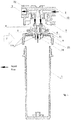
- FIG. 1 illustrates the cross-section of the housing structure
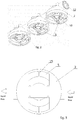
- fig. 2 illustrates the 3D view of filter housing elements when several filter housings according to the invention are set in one filtering line with three filtering levels
- fig. 3 illustrates a top view of the head unit of the housing according to the invention, with visible additional hitches.
- the on-pipe filter housing for liquids, particularly intended for water, contains a body 1 and a head unit 2, which mutually cooperate through an intermediate, severable, mounted on the head unit 2, preferably screwed-in to the body 1 lid 3 with a connecting stub pipe 4, which is stabilized in the connecting inlet of the head unit by a rotary-ratchet mechanism 5.
- the connecting stub pipe 4 is equipped with O-rings 6 placed in round notches.
- the lid 3 with the connecting stub pipe 4 is generally shaped as a cap 7, screwed onto the housing body 1, from which a stub pipe 4 directed towards the body 1 protrudes, and the diameter of the stub pipe is smaller than the diameter of the cap 7, and at least two solid ledges 8 cooperating with the rotary-ratchet mechanism 5 of the head unit 2 are placed on the surface of the cap 7, around the connecting stub pipe 4, consolidated with the stub pipe 4 and with the cap by means of the injection method.
- the lid 3 with the connecting stub pipe 4 has a pass-through, axial hole 9, the position of which corresponds to the position of a liquid outlet 10, particularly intended for water, in the head unit 2, and a second pass-through liquid inlet 11, particularly intended for water, feeding the liquid from the body 1, the position of which with the lid 3 assembled on the body 1 and the lid 3 - in the head unit 2 of the housing according to the invention corresponds to the position of the liquid inlet 12, particularly intended for water.
- the pass-through axial hole 10 is beneficially shaped as a funnel 14, narrowing towards the interior of the body 1, and is surrounded by at least one additional ring 13, pressing on the filtering pad (not illustrated in the figure).
- a seal is placed between the body 1 and the lid 3 with the connecting stub pipe 4, and the connecting stub pipe 4 is centrally placed on the cap, in a manner that its longitudinal axis corresponds with the direction of rotation of the cap 7.
- the solid ledges 8 placed around the connecting stub pipe 4 are primarily shaped like fragments of a screw line, partially flattened and parallel to the enclosed surface of the cap 7, and their beginnings and ends are placed at an angle in reference to the enclosed surface of the cap 7.
- a rotary-ratchet mechanism 5 is placed inside the head unit 2 of the on-pipe filter housing according to the invention.
- the mechanism 5 comprises solid ledges 5 consolidated with the head unit 2 by means of the injection method, facing the head unit's 2 axis, , whereas their number corresponds to the number of solid ledges intended to cooperate with the rotary-ratchet mechanism 5 of the head unit 2.
- the structure of the ledges 5 in the head unit 2 includes additional hitches 15, protruding in the head unit's 2 direction of movement, which form small ribs, which additionally connect the ledges 15 on the head unit 2 with the material of the lateral surface of the head unit 2.
- hitch 15 sockets formed into notches with corresponding shapes and sizes to the shapes and sizes of the hitches 15, are placed in the material of the ledges 8 placed around the connecting stub pipe 4.
- the filter housing head unit 2 is a rotary unit formed by connecting at least: a cylinder containing a rotary-ratchet mechanism, topped with a copula resembling a truncated hemisphere, enclosed from the top, and at least one cylinder with fixtures for connecting to installations, perpendicular to the head unit's direction of rotation, piercing through the copula.
- the round, hemisphere shape of the copula evenly distributes the forces inside the housing and resulting from the hydrostatic and hydrodynamic pressures acting inside the housing, and allows for the use of a filter in a housing according to the invention in installations with relatively high pressure levels.
- the connecting fixtures are contra-rotating and are equipped with a ribbing on their external surfaces, laid perpendicularly to the axes of the connecting holes.
- brass pads with female threads with enwrapping seals in the form of one O-ring per every pad, placed between the pad and the housing are placed inside the connecting fixtures.
- the connecting stub pipes i.e. the water inlet and outlet, are extensions of the feed ducts placed inside the head unit, at an angle close to perpendicular to the axis of the connecting stub pipes.
- the female thread inside the lid with the connecting stub pipe matches in size the thread in the upper part of the cylindrical body.
- One of the threads is rectangular and rounded at the tip.
- Such a threaded connection of the body and the head unit with the connecting stub pipe additionally reinforces the connection, protecting it from accidental unscrewing and/or leaking in result of installation vibrations caused by water flow and flow velocity changes.
- a round notch with an O-ring sealing the housing is placed on the threaded surface of the lid with the connecting stub pipe.
Landscapes
- Chemical & Material Sciences (AREA)
- Life Sciences & Earth Sciences (AREA)
- Hydrology & Water Resources (AREA)
- Engineering & Computer Science (AREA)
- Environmental & Geological Engineering (AREA)
- Water Supply & Treatment (AREA)
- Organic Chemistry (AREA)
- Chemical Kinetics & Catalysis (AREA)
- Filtration Of Liquid (AREA)
Priority Applications (1)
| Application Number | Priority Date | Filing Date | Title |
|---|---|---|---|
| EP16191922.0A EP3300785A1 (fr) | 2016-09-30 | 2016-09-30 | Filtre pour liquides |
Applications Claiming Priority (1)
| Application Number | Priority Date | Filing Date | Title |
|---|---|---|---|
| EP16191922.0A EP3300785A1 (fr) | 2016-09-30 | 2016-09-30 | Filtre pour liquides |
Publications (1)
| Publication Number | Publication Date |
|---|---|
| EP3300785A1 true EP3300785A1 (fr) | 2018-04-04 |
Family
ID=58347021
Family Applications (1)
| Application Number | Title | Priority Date | Filing Date |
|---|---|---|---|
| EP16191922.0A Withdrawn EP3300785A1 (fr) | 2016-09-30 | 2016-09-30 | Filtre pour liquides |
Country Status (1)
| Country | Link |
|---|---|
| EP (1) | EP3300785A1 (fr) |
Citations (9)
| Publication number | Priority date | Publication date | Assignee | Title |
|---|---|---|---|---|
| US3262570A (en) | 1963-02-05 | 1966-07-26 | Commercial Filter Corp | Filtration assemblies and replaceable elements of such assemblies |
| US5336406A (en) * | 1993-01-26 | 1994-08-09 | Elkay Manufacturing Company | Replaceable filter cartridge and head assembly with safety shut-off valve |
| US5445734A (en) | 1994-11-18 | 1995-08-29 | Chen; Ching-Wen | Water filter |
| US5985143A (en) | 1998-09-08 | 1999-11-16 | Lin; Maw-Chang | Structure water filter outer shell |
| US6197193B1 (en) | 1999-10-21 | 2001-03-06 | Virgil L. Archer | Drinking water filter |
| PL60723Y1 (en) | 1998-11-13 | 2004-09-30 | Formaster Sa | Water purification filter for obtaining potable water |
| CN2766122Y (zh) | 2005-01-10 | 2006-03-22 | 余泽强 | 一种过滤器多选阀 |
| WO2012178179A2 (fr) * | 2011-06-23 | 2012-12-27 | Apiqe Inc. | Cartouche filtrante jetable destinée à un distributeur d'eau |
| US20140158590A1 (en) * | 2012-12-07 | 2014-06-12 | General Electric Company | Apparatus for a parallel flow manifold system for water filtration |
-
2016
- 2016-09-30 EP EP16191922.0A patent/EP3300785A1/fr not_active Withdrawn
Patent Citations (9)
| Publication number | Priority date | Publication date | Assignee | Title |
|---|---|---|---|---|
| US3262570A (en) | 1963-02-05 | 1966-07-26 | Commercial Filter Corp | Filtration assemblies and replaceable elements of such assemblies |
| US5336406A (en) * | 1993-01-26 | 1994-08-09 | Elkay Manufacturing Company | Replaceable filter cartridge and head assembly with safety shut-off valve |
| US5445734A (en) | 1994-11-18 | 1995-08-29 | Chen; Ching-Wen | Water filter |
| US5985143A (en) | 1998-09-08 | 1999-11-16 | Lin; Maw-Chang | Structure water filter outer shell |
| PL60723Y1 (en) | 1998-11-13 | 2004-09-30 | Formaster Sa | Water purification filter for obtaining potable water |
| US6197193B1 (en) | 1999-10-21 | 2001-03-06 | Virgil L. Archer | Drinking water filter |
| CN2766122Y (zh) | 2005-01-10 | 2006-03-22 | 余泽强 | 一种过滤器多选阀 |
| WO2012178179A2 (fr) * | 2011-06-23 | 2012-12-27 | Apiqe Inc. | Cartouche filtrante jetable destinée à un distributeur d'eau |
| US20140158590A1 (en) * | 2012-12-07 | 2014-06-12 | General Electric Company | Apparatus for a parallel flow manifold system for water filtration |
Similar Documents
| Publication | Publication Date | Title |
|---|---|---|
| SG191123A1 (en) | Filtration system and assembly thereof | |
| JPH06154660A (ja) | スプレーノズル装置 | |
| US7338092B1 (en) | Quick-release connector fitting | |
| CA2531945A1 (fr) | Distributeur de liquides | |
| US9217580B2 (en) | Hose attachment device for clearing drain lines | |
| EP0029368B1 (fr) | Procédé de montage ou de démontage d'un tournant de vanne | |
| EP3300785A1 (fr) | Filtre pour liquides | |
| CA2589842C (fr) | Corps de vanne universel pour liquide | |
| CN203348615U (zh) | 一种具有过滤功能的球阀 | |
| US11814822B2 (en) | Plumbing fitting | |
| CN203291616U (zh) | 一种阀门过滤器 | |
| US12473987B2 (en) | Low-profile paired relief valve | |
| DE102010027879B4 (de) | Verbindungseinheit zum Anschluss einer Fluidleitung an eine Wasserbettmatratze | |
| CA2895114A1 (fr) | Adaptateur de robinet d'arret pour sortie de joint mecanique | |
| CN207406581U (zh) | 插装式液压过滤器 | |
| KR20170003907U (ko) | 업소용 가스버너장치의 관이음 | |
| CN103527829A (zh) | 一种流体稳压阀 | |
| CN203857089U (zh) | 干式集水分水器 | |
| CN213178817U (zh) | 一种具有过滤功能的出水接头组件及热水器 | |
| CN104121373A (zh) | 压力可调式旁通阀 | |
| CN203585635U (zh) | 一种净水器稳压接头 | |
| CN214500402U (zh) | 一种密封快拆连接件 | |
| EP2407724A2 (fr) | Armature de remplissage d'une installation de chauffage | |
| US20140158217A1 (en) | Backwash fitting | |
| CN211624506U (zh) | 一种方便拆装和维修的液压调节阀门 |
Legal Events
| Date | Code | Title | Description |
|---|---|---|---|
| PUAI | Public reference made under article 153(3) epc to a published international application that has entered the european phase |
Free format text: ORIGINAL CODE: 0009012 |
|
| STAA | Information on the status of an ep patent application or granted ep patent |
Free format text: STATUS: THE APPLICATION HAS BEEN PUBLISHED |
|
| AK | Designated contracting states |
Kind code of ref document: A1 Designated state(s): AL AT BE BG CH CY CZ DE DK EE ES FI FR GB GR HR HU IE IS IT LI LT LU LV MC MK MT NL NO PL PT RO RS SE SI SK SM TR |
|
| AX | Request for extension of the european patent |
Extension state: BA ME |
|
| STAA | Information on the status of an ep patent application or granted ep patent |
Free format text: STATUS: REQUEST FOR EXAMINATION WAS MADE |
|
| 17P | Request for examination filed |
Effective date: 20190109 |
|
| RBV | Designated contracting states (corrected) |
Designated state(s): AL AT BE BG CH CY CZ DE DK EE ES FI FR GB GR HR HU IE IS IT LI LT LU LV MC MK MT NL NO PL PT RO RS SE SI SK SM TR |
|
| STAA | Information on the status of an ep patent application or granted ep patent |
Free format text: STATUS: THE APPLICATION IS DEEMED TO BE WITHDRAWN |
|
| 18D | Application deemed to be withdrawn |
Effective date: 20181005 |