EP3300870A1 - Procédé et dispositif de fabrication d'un élément de grille à colonnes longitudinales - Google Patents
Procédé et dispositif de fabrication d'un élément de grille à colonnes longitudinales Download PDFInfo
- Publication number
- EP3300870A1 EP3300870A1 EP17189871.1A EP17189871A EP3300870A1 EP 3300870 A1 EP3300870 A1 EP 3300870A1 EP 17189871 A EP17189871 A EP 17189871A EP 3300870 A1 EP3300870 A1 EP 3300870A1
- Authority
- EP
- European Patent Office
- Prior art keywords
- longitudinal
- concrete
- longitudinal beams
- mold
- beams
- Prior art date
- Legal status (The legal status is an assumption and is not a legal conclusion. Google has not performed a legal analysis and makes no representation as to the accuracy of the status listed.)
- Granted
Links
Images



Classifications
-
- B—PERFORMING OPERATIONS; TRANSPORTING
- B28—WORKING CEMENT, CLAY, OR STONE
- B28B—SHAPING CLAY OR OTHER CERAMIC COMPOSITIONS; SHAPING SLAG; SHAPING MIXTURES CONTAINING CEMENTITIOUS MATERIAL, e.g. PLASTER
- B28B7/00—Moulds; Cores; Mandrels
- B28B7/16—Moulds for making shaped articles with cavities or holes open to the surface, e.g. with blind holes
- B28B7/18—Moulds for making shaped articles with cavities or holes open to the surface, e.g. with blind holes the holes passing completely through the article
- B28B7/186—Moulds for making shaped articles with cavities or holes open to the surface, e.g. with blind holes the holes passing completely through the article for plates, panels or similar sheet- or disc-shaped objects, also flat oblong moulded articles with lateral openings, e.g. panels with openings for doors or windows, grated girders
-
- A—HUMAN NECESSITIES
- A01—AGRICULTURE; FORESTRY; ANIMAL HUSBANDRY; HUNTING; TRAPPING; FISHING
- A01K—ANIMAL HUSBANDRY; AVICULTURE; APICULTURE; PISCICULTURE; FISHING; REARING OR BREEDING ANIMALS, NOT OTHERWISE PROVIDED FOR; NEW BREEDS OF ANIMALS
- A01K1/00—Housing animals; Equipment therefor
- A01K1/015—Floor coverings, e.g. bedding-down sheets ; Stable floors
- A01K1/0151—Grids; Gratings; Slatted floors
-
- B—PERFORMING OPERATIONS; TRANSPORTING
- B28—WORKING CEMENT, CLAY, OR STONE
- B28B—SHAPING CLAY OR OTHER CERAMIC COMPOSITIONS; SHAPING SLAG; SHAPING MIXTURES CONTAINING CEMENTITIOUS MATERIAL, e.g. PLASTER
- B28B7/00—Moulds; Cores; Mandrels
- B28B7/0064—Moulds characterised by special surfaces for producing a desired surface of a moulded article, e.g. profiled or polished moulding surfaces
- B28B7/0082—Moulds characterised by special surfaces for producing a desired surface of a moulded article, e.g. profiled or polished moulding surfaces with surfaces for moulding parallel grooves or ribs
Definitions
- the invention relates to Lekssspaltenrostiata for animal houses. Specifically, a method and an apparatus for producing such longitudinal cascade gratings made of concrete will be described.
- Prefabricated concrete longitudinal crevice gratings designed in an animal house (e.g., cowshed housing) for producing a floor are well known.
- Such Leksspaltenrostiata consist of two or more spaced-apart and arranged in a plane longitudinal beams and two or more spaced-apart and arranged in the plane of the longitudinal beams crossbar.
- a longitudinal gap is defined, which is intended for the disposal of animal faeces and veterinarians.
- Tierböden from prefabricated Leksspaltenrostmaschinen may, due to accumulated on the ground faeces and urine, become slippery. There is thus the risk that animals slip over the smooth surface of the ground and injure themselves when walking.
- the soil grip can be significantly improved.
- there are several approaches to applying surface structures For example, from the EP 1 563 728 B1 a method for the production of prefabricated longitudinal crevice gratings made of concrete for laying in an animal house known in which grooves are cut or milled on the surface of the longitudinal crevice grid elements. The cutting or milling process is carried out here after delimbing the L Lucassspaltenrostiata and partially cured concrete. The grooves thus produced extend in the longitudinal direction of the longitudinal beams and are rectangular in cross-section. The cutting of grooves can damage the concrete structure of the partially cured concrete, causing the mechanical strength of the grate elements decreases. Furthermore, sharp cutting or milling edges can arise, which can lead to injury to the animals.
- a method for the production of longitudinal crevice grating elements in which the surface of the longitudinal crevice grating elements is provided with a rubber coating.
- the rubber coating may in this case have a surface structure (such as surface grooves).
- the rubber coating is partially pressed into the fresh concrete during the production of the longitudinal ribbing elements.
- the attachment of the rubber elements requires a thorough monitoring of the manufacturing process. In particular, care must be taken that the concrete displaced when the rubber coating is pushed in can escape from the concrete casting mold.
- Object of the present invention is to provide a technically easy to implement and cost-effective technique for the production of Lekssspaltenrostmaschinen. It is a further object of the present invention to produce longitudinal splitting grids with improved surface properties and improved strength.
- a method for producing a concrete cascade comprising at least two longitudinal beams spaced apart and arranged in a plane and at least two transverse beams spaced apart and arranged in the plane of the longitudinal beams and crossing the at least two longitudinal beams , wherein in each case a longitudinal gap is defined by two adjacent longitudinal beams and two adjacent transverse beams.
- the indenting process can be mechanical or electromechanical.
- a pressure force can be applied to the at least one embossing element in such a way that the embossing element is pressed into the concrete on the exposed concrete surface.
- an oscillatory vibration movement can be exerted on the at least one embossing element. In this way, the at least one embossing element can be pressed particularly gently into the concrete.
- the exposed surface of the longitudinal crevice grid element can be further roughened in addition to the structuring described here by depressions.
- the method may include an additional process step of roughening the surface of the longitudinal crevice grid element.
- the process step of the roughening of the surface of the longitudinal column grid element can in this case a sprinkling of the surface with Include quartz sand or split.
- the step of roughening may include performing a brush stroke.
- brush stroke may be meant roughening of the surface in which a broom is pulled uniformly across the surface of the fresh concrete along a predetermined direction.
- the at least one embossing element can be configured and dimensioned such that it deforms (recesses) the surface of the Lekssspaltenrostelements only at the Eindschreibstellen during Eindschreibvorgang.
- surface areas of the longitudinal crevice grating element which surround the indentation points can remain unaffected by the indenting process. Thus, limited to the Eindschreibstellen local deformation (depression) is achieved.
- the at least one embossing element in the pushing-in direction and in a plane perpendicular to the pushing-in direction
- Displacement effects such as a bulging of the surface in the immediate vicinity of the wells due to concrete displacement during Eindgurvorgang are negligible. In particular, no provision must be made to drain the displaced amount of concrete from the molds.
- the step of creating a surface structure may further comprise aligning (orienting) the at least one embossing element with respect to the exposed surface of the longitudinal groove member.
- the alignment process may include aligning the at least one embossing element with respect to the longitudinal beams and / or transom. By the alignment process thus the orientation of the depressed recesses in the longitudinal beams and / or transom is determined.
- the at least one embossing element may be oriented such that each of the indented recesses is arranged parallel, perpendicular or at a predetermined angle to the longitudinal direction of the longitudinal beams (hereinafter longitudinal beam direction). It is also conceivable that the indented recesses in the longitudinal beam direction may have different orientations.
- the at least one embossing element may be formed such that the recess pressed in by the at least one embossing element forms a groove with a straight line or a groove is curved line shape.
- the groove may have a zig-zag line shape.
- each groove can have a triangular cross-section (triangular groove).
- the triangular groove may have a tip indented in the concrete which encloses an angle in the range between 45 ° and 90 °, preferably an angle of approximately 60 °.
- the surface structure may comprise at least two grooves per longitudinal beam, which are arranged spaced from each other. It is understood that instead of two grooves and three, four or more grooves per longitudinal beam can be realized.
- the at least two grooves can be generated by means of a single push-in step (ie simultaneously). Alternatively, it is also conceivable that the at least two grooves are generated sequentially, that is, by performing a plurality of successive following Eindschreib Kunststoffe.
- the step of releasing the longitudinal creel from the mold may comprise the substeps of: rotating the mold so that the exposed surface of the longitudinal creel with the indented surface features face down; and then de-scaling the longitudinal creel member downwardly from the mold.
- an apparatus for producing a concrete cascade comprising at least two longitudinal beams spaced from each other and arranged in one plane and at least two transverse beams arranged at a distance from one another in the plane of the longitudinal beams and crossing the at least two longitudinal beams adjacent longitudinal beams and two adjacent transverse beams each having a longitudinal gap defined
- said device comprising: a mold having the shape of the longitudinal column grid member corresponding, upwardly open casting spaces, which are intended to receive the concrete provided in a filling process; a vibrating table on which the mold is placed, the vibrating table being arranged to shake the mold during the filling operation to achieve a uniform concrete distribution in the casting spaces; and an indenting device having at least one embossing element, said embossing device being adapted to locally depress the at least one embossing element into the concrete of the longitudinal beams to create a surface structure on the exposed surface of the longitudinal beams.
- the at least one embossing element can be dimensioned so that it displaces a concrete volume during Eind Wegvorgang, which is negligible compared to the filled with concrete volume of the Lssensspaltenrostelements.
- the at least one embossing element may be rod-shaped with a predetermined length, width and depth dimensions.
- the at least one rod-shaped embossing element may have a triangular cross section or at least comprise a tip with a triangular cross section.
- the tip of the triangular embossing element may in this case form an angle in the range of 45 ° to 90 °, preferably an angle of approximately 60 °.
- the indenting device may have a single embossing element.
- the indenting device may have at least two spaced-apart embossing elements. In this way, at least two depressions (grooves) can be realized on the exposed surface of the longitudinal column grid element per indentation process.
- the push-in device may further comprise a pressure device, which is provided to pressurize the at least one embossing element with an (oscillating) pressure.
- the pressure to be applied can be preset or presettable.
- the push-in device may comprise an orientation device. This is intended to align the at least one embossing elements with respect to the Lekssspaltenrostelements.
- the device may further comprise a lifting device. This is coupled to the indenting device or coupled and provided to lower the indenting device during the Eind Wegvorgangs in the direction of the Lssensspaltenrostelements and to raise again after completion of the Eind Wegvorgangs.
- the device may further comprise a control device which is provided to control the indenting device and the lifting device in order to perform the indenting operation.
- the control device can be designed to control the orientation device of the push-in device for aligning the at least one embossing element.
- the control device may be provided for controlling the lifting device for lowering and / or raising the indenting device.
- the device may further comprise a tilting device, which is intended to rotate the mold after the surface structure has been produced, so that the exposed surface of the longitudinally spaced ribbed element with the pressed-in surface structure points downwards, and is subsequently detachable.
- a tilting device which is intended to rotate the mold after the surface structure has been produced, so that the exposed surface of the longitudinally spaced ribbed element with the pressed-in surface structure points downwards, and is subsequently detachable.
- a longitudinal cascade of concrete which can be produced by the method and apparatus described above.
- the Leksspaltenrostelement comprises at least two mutually spaced and arranged in a plane longitudinal beams and at least two spaced apart and arranged in the plane of the longitudinal beams and the at least two longitudinal beams crossing crossbar, wherein two adjacent longitudinal beams and two adjacent cross beams each have a longitudinal gap is defined, characterized in that at least the surface of the longitudinal slots has one or more recesses (grooves) each having a triangular cross-sectional profile.
- Each of the triangular depressions may have a tip pressed in the concrete, which has an angle in the range between 45 ° and 90 °, preferably an angle of approximately 60 °.
- the groove depth can be in the range between 2-20 mm, preferably in the range between 2-10 mm, more preferably in the range between 2-5 mm.
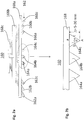
- Fig. 1 1 shows a schematic cross-section of the device 100.
- the device 100 comprises a vibrating table 110 with a vibrator motor 112, a casting mold 130 arranged on the vibrating table 110 with a plurality of casting spaces 132a, 132b, 132c and an injection device 160 arranged above the casting mold 130.
- the device 100 can optionally also include a support means 120 which is arranged between the vibrating table 110 and a bottom 136 of the mold 130 and is provided for supporting the mold 120. It is understood that according to an alternative variant, the device 100 can also rest directly on the vibrating table 110.
- the device 100 may include a lifting device coupled to the push-in device 160, which is provided for lowering and raising the push-in device 160.
- a lifting device coupled to the push-in device 160, which is provided for lowering and raising the push-in device 160.
- Fig. 1 only one part 170 of the lifting device is shown schematically.
- the lifting and lowering movement of the indenting device 160 is in Fig. 1 represented by the arrow 180.
- the casting spaces 132a, 132b, 132c of the casting mold 130 are designed to be open towards the top (ie, to the surface 134 of the casting mold 130). Thus, the casting spaces 132a, 132b, 132c can be filled from above with fresh concrete.
- the casting spaces 132a, 132b, 132c are constructed to correspond to the shape of the longitudinal creel member to be produced.
- Gussform 130 shown by way of example has three upwardly open casting spaces 132a, 132b, 132c with a trapezoidal cross section and is configured to form a longitudinal crevice grating element 140 with three longitudinal bars 142, 144, 146 arranged parallel to one another.
- Such a Leksspaltenrostelement 140 is in the FIGS. 5a-5e shown. It is understood that the number of casting spaces 132a, 132b, 132c and their shape depends on the shape of the longitudinal crevice grid element to be produced, and on that in the Fig. 1 may differ form shown. For example, the Lekspaltenrostelements 140 different from those in the FIGS. 5a-5e embodiments shown also have two longitudinal beams or four, five or more longitudinal beams. Accordingly, the mold 130 is equipped with two casting spaces or four, five or more casting spaces for forming longitudinal beams.
- the vibrating table 110 is configured to perform a shaking motion. This is transferred to the mold 130 carried by the vibrating table 110. By the shaking motion of the mold 130, the concrete filled in the casting spaces 132a, 132b, 132c is uniformly distributed and compacted in the casting spaces 132a, 132b, 132c.
- the longitudinal column grate element 140 is formed.
- the casting spaces 132a, 132b, 132c are filled to the top of the casting mold 134 with concrete.
- An exposed surface 147 of the longitudinal slot grid element 140 which can be patterned with the aid of the push-in device 160, thus arises on the casting mold top 134.
- the indenting device 160 provided for structuring the exposed surface 147 comprises at least one embossing element 162 and a bearing device 168 on which the at least one embossing element 162 is mounted.
- the indenter 160 is movable up and down with respect to the mold 130 mounted on the vibrating table 110 (see arrow 180) to create a surface structure on the exposed surface 147.
- the structuring of the exposed surface 147 by means of the indenting device 160 will be further described below.
- Fig. 2a shows a three-dimensional view of the in Fig. 1
- the indenting device 160 comprises a total of nine embossing elements 162a-c, 164a-c, 166a-c, wherein in each case three embossing elements are combined to form a group. Within each group are the embossing elements 162a-c. 164a-c, 166a-c are spaced from each other and arranged parallel to each other. Each triad is provided for the surface structuring of one of the three longitudinal beams 142, 144, 146.
- the grouped embossing elements 162a, 162b, 162c are in this case attached to three bearing elements 168a-c.
- three parallel recesses are pressed on the exposed surface 147 of each longitudinal bar 142, 144, 146.
- the indenter 160 per longitudinal beam 142, 144, 146 may also have fewer or more than three embossing elements.
- each of the embossing elements 162a-c, 164a-c, 166a-c is formed as a rectilinear rod with a triangular cross-sectional profile.
- the triangular bars are each coupled with a bar edge to the bearing elements 168a-c.
- the two remaining rod edges form a point that is pressed into the concrete, creating a groove with a triangular cross-section in the concrete.
- the embossing elements 162a-c, 164a-c, 166a-c may also differ from the configuration of a triangular bar described herein.
- each embossing element at its einzug Wegenden in the concrete section has a triangular cross-sectional profile for generating a triangular groove in the concrete.
- the length of the rod-shaped embossing elements 162a-c, 164a-c, 166a-c can be dimensioned differently depending on the type of surface structuring and the dimension of the longitudinal crevice grate element.
- the length of the rod-shaped embossing elements 162a-c, 164a-c, 166a-c substantially corresponds to the length of the longitudinal crevice grid element 140 to be structured.
- the embossing elements 162a-c, 164a-c, 166a-c may be made of metal (eg steel, Aluminum), a metal alloy, plastic or be formed from another material.
- the triangular cross-sectional profile of the embossing elements 162a-c, 164a-c, 166a-c is based on Fig. 2b further described.
- the embossing elements 162a-c, 164a-c, 166a-c have a downwardly pointing tip A, which is pressed into the concrete.
- a first cross-sectional side b and second cross-sectional side c forming the tip A are essentially of equal length and are inclined relative to each other such that they enclose an angle ⁇ at the tip A which lies in the range between 45 ° and 90 °.
- the cross-sectional side a acts as a bearing side, by means of which the embossing elements 162a-c, 164a-c, 166a-c are mechanically connected to the bearing elements 168a-c.
- the advantages of the triangular configuration of the embossing elements described here are based on FIGS. 4a and 4b further explained.
- the mold 130 is first provided and placed on the vibrating table 110 of the apparatus 100.
- the casting spaces 132a, 132b, 132c open at the upper side 134 of the casting mold 130 are filled with concrete.
- fresh concrete at the upper side 134 of the casting mold 130 is filled into the casting spaces 132a, 132b, 132c until the casting spaces 132a, 132b, 132c are filled with concrete up to the upper side 134 of the casting mold 130.
- the exposed concrete surface 147 of the L Lucassspaltentrostelements 140 thus arises at the top 134.
- the mold 130 is vibrated by means of the vibrating table 110 (step S30). In this way, the concrete in the casting spaces 132a, 132b, 132c is evenly distributed and compacted. After the casting spaces 132a, 132b, 132c are completely filled, the shaking operation is ended. If necessary, the concrete surface 147 exposed at the top 134 is further smoothed. In order to increase the grip of the concrete surface, in an optional process step, the concrete surface can be sprinkled with split or quartz sand or evenly roughened with the aid of a broom.
- the exposed concrete surface 147 is further structured by means of the indenting device 160.
- the indenting process is carried out as long as the concrete in the casting spaces 132a-132b, 132c is fresh (ie not yet partially hardened).
- the indenting device 160 is lowered in the direction of the surface 134 of the mold 130 or the exposed surface 147 until a lower edge of the bearing device 168 has reached a presettable height distance H1 to the top 134 of the mold or exposed surface 147 (see Fig. 4a ).
- the indentation process can be limited to certain surface areas.
- the peak depth t of the embossing elements 162a-c, 164a-c, 166a-c is chosen so that the embossing elements 162a-c, 164a-c, 166a-c during the crimping process grooves 142a-c, 144a-c. 146a-c with a given depth t1 and a given surface width a1 (see Fign 4b and 5a ).
- Typical indentation depths t1 are in the range of 2-15 mm, preferably in the range between 2 to 10 mm, more preferably in the range between 2-5 mm.
- Typical surface widths a1 of the grooves 142a-c, 144a-c. 146a-c are in the range between 3-10 mm, preferably in the range 3-6 mm (see Fig. 4b ).
- the indenting device 160 is raised again (eg to a predetermined height value H2), whereby the embossing elements 162a-c, 164a-c, 166a-c from the indented grooves 142a-c, 144a-c. 146a-c are removed.
- the embossing elements 162a-c, 164a-c, 166a-c By removing the embossing elements 162a-c, 164a-c, 166a-c, the three-channel grooves 142a-c, 144a-c pressed in the concrete remain.
- 146a-c which extend in the longitudinal direction of the longitudinal beams 142, 144, 146. These give the concrete surface 147 the desired rough surface characteristic for improving the grip (cf. FIGS. 4b .
- the method step of lifting the push-in device 160 can take place immediately after the push-in operation, ie, as long as the concrete is still fresh and not partially cured.
- a concrete or concrete mixture is used which retains its consistency when fresh.
- the indentation time can be limited to a few seconds to minutes.
- a final step S60 the shaped and surface-structured longitudinal crevice member 140 is released from the mold 130.
- the casting mold 130 is rotated by 180 ° with the aid of the tilting device, so that the exposed, structured surface 147 points downwards.
- the longitudinal crevice grating element 140 will be released from the mold 130 downwards (in FIG Fig. 1 not shown).
- the described triangular shape of the embossing elements 162a-c, 164a-c, 166a-c further enables a gentle embossing process.
- the triangular tips A penetrate gently into the fresh concrete and displace it gradually laterally outwards.
- the concrete along the angle ⁇ forming groove edges 141, 143 further compressed and thus strengthened (see. Fig. 4b ).
- the strength of the concrete surface and the quality of the grooves is thus further increased.
- the concrete structure is not damaged by the Eindschreibvorgang described, as is often the case, for example, when cutting or milling grooves.
- Another benefit of the triangular shape of the embossing elements 162a-c, 164a-c, 166a-c described herein is that at the location of the indented grooves 142a-c, 144a-c. 146a-c on the surface 147 no sharp edges arise.
- the obliquely downwardly tapered groove edges 141, 143 form with the horizontal surface 147 has an obtuse angle ⁇ , which exceeds 90 ° (see. Fig. 4b ). In this way, sharp transitions are avoided, which significantly increases the comfort for animals.
- a further benefit of the triangular shape of the embossing elements 162a-c, 164a-c, 166a-c and indented grooves 142a-c, 144a-c, 146a-c described herein is that the concrete surface is only locally modified by the imprinting process the triangular shape the displaced concrete volume is very small. Assuming that the indented grooves 142a-c, 144a-c.
- FIGS. 4a and 4b The advantages of the push - in technique described here are discussed in connection with FIGS. 5a-5e different embossing structures further discussed.
- FIGS. 5a and 5b is the Lekssspaltenrostelement 140 shown, as it can be realized for example with the Eindschreib worn 160 described.
- Fig. 5a shows a 3D view of the L Lucassspaltenrostelements 140
- Fig. 5b the longitudinal split grate element 140 is shown again in a plan view. It has three longitudinal beams 142, 144, 146 and three transverse beams 141, 143, 145.
- the longitudinal beams 142, 144, 146 have a surface structure 150 which comprises three rectilinear grooves 142a-c, 144a-c, 146a-c of each longitudinal beam 142, 144, 146 with a triangular cross-sectional profile.
- the grooves can be arranged perpendicular to the direction of the longitudinal beams 142, 144, 146.
- Such a surface structure 250 is shown in FIG Fig. 5c shown.
- the indented grooves may be obliquely aligned with respect to the longitudinal beam edges.
- a surface structure 350 is shown in which the indented grooves along the longitudinal beams 142, 144, 146 mimic a zig-zag line shape.
- a waveform is also conceivable.
- a surface structure 450 is shown in which domains of different groove orientation alternate along the longitudinal beams 142, 144, 146.
- the soil grip can be significantly improved.
- All of the surface structures 150, 250, 350, 450 described here have in common that the indented grooves have a triangular cross-sectional profile, as in connection with FIGS FIGS. 3 . 4a-4b has been described above. They differ only in the orientation (orientation) and length of the grooves. All of the surface structures 150, 250, 350, 450 described herein can be used with the in Fig. 1 shown device 100 can be realized. It is only necessary to adjust the alignment and length dimensions of the embossing elements of the surface structure to be realized.
Landscapes
- Engineering & Computer Science (AREA)
- Life Sciences & Earth Sciences (AREA)
- Mechanical Engineering (AREA)
- Environmental Sciences (AREA)
- Manufacturing & Machinery (AREA)
- Chemical & Material Sciences (AREA)
- Ceramic Engineering (AREA)
- Biodiversity & Conservation Biology (AREA)
- Animal Husbandry (AREA)
- Zoology (AREA)
- Press-Shaping Or Shaping Using Conveyers (AREA)
- Sewage (AREA)
- Moulds, Cores, Or Mandrels (AREA)
- Adornments (AREA)
Priority Applications (4)
| Application Number | Priority Date | Filing Date | Title |
|---|---|---|---|
| RS20211579A RS62772B1 (sr) | 2016-09-07 | 2017-09-07 | Postupak i uređaj za proizvodnju uzdužnog elementa sa prorezima |
| PL17189871T PL3300870T3 (pl) | 2016-09-07 | 2017-09-07 | Sposób i urządzenie do wytwarzania elementu rusztu ze szczelinami podłużnymi |
| SI201731017T SI3300870T1 (sl) | 2016-09-07 | 2017-09-07 | Postopek in naprava za izdelavo rešetkastega elementa z vzdolžnimi režami |
| HRP20220013TT HRP20220013T1 (hr) | 2016-09-07 | 2017-09-07 | Postupak i uređaj za izradu uzdužno prorezanog elementa |
Applications Claiming Priority (1)
| Application Number | Priority Date | Filing Date | Title |
|---|---|---|---|
| DE102016116703.7A DE102016116703A1 (de) | 2016-09-07 | 2016-09-07 | Verfahren und Vorrichtung zur Herstellung eines Längsspaltenrostelements |
Publications (2)
| Publication Number | Publication Date |
|---|---|
| EP3300870A1 true EP3300870A1 (fr) | 2018-04-04 |
| EP3300870B1 EP3300870B1 (fr) | 2021-11-10 |
Family
ID=59846399
Family Applications (1)
| Application Number | Title | Priority Date | Filing Date |
|---|---|---|---|
| EP17189871.1A Active EP3300870B1 (fr) | 2016-09-07 | 2017-09-07 | Procédé et dispositif de fabrication d'un élément de grille à colonnes longitudinales |
Country Status (7)
| Country | Link |
|---|---|
| EP (1) | EP3300870B1 (fr) |
| DE (1) | DE102016116703A1 (fr) |
| HR (1) | HRP20220013T1 (fr) |
| HU (1) | HUE057918T2 (fr) |
| PL (1) | PL3300870T3 (fr) |
| RS (1) | RS62772B1 (fr) |
| SI (1) | SI3300870T1 (fr) |
Citations (4)
| Publication number | Priority date | Publication date | Assignee | Title |
|---|---|---|---|---|
| CH86139A (fr) * | 1919-11-21 | 1920-08-02 | Hegi Emile | Ecurie. |
| CA2324134A1 (fr) * | 2000-10-24 | 2002-04-24 | Syri-Con Corporation | Dalle en beton prefabrique |
| EP1916080A2 (fr) * | 2006-10-27 | 2008-04-30 | METTEN Stein + Design GmbH & Co. KG | Méthode pour la formation de blocs et/ou plaques de béton |
| JP2011037649A (ja) * | 2009-08-07 | 2011-02-24 | Ueda Shokai:Kk | 畜舎設備用のコンクリート製品及びその製造方法 |
Family Cites Families (4)
| Publication number | Priority date | Publication date | Assignee | Title |
|---|---|---|---|---|
| CA2225093A1 (fr) | 1998-01-28 | 1999-07-28 | Bruno Dupuis | Machine de moulage de plaque de beton ameliore pour produire des plaquesplus securitaire et plus facile a nettoyer |
| DK200300090A (da) | 2003-01-24 | 2004-07-25 | Perstrup Beton Ind As | Fremgangsmåde til fremstilling af staldgulvselementer med elastisk trædeflade |
| EP1563728B1 (fr) | 2004-02-13 | 2006-06-07 | VAN DER VELDEN BETON, naamloze vennootschap | Procédé de fabrication des éléments de caillebotis en beton pour plancher d'étable pour le bétail et similaire |
| DK2138289T3 (da) | 2008-06-23 | 2011-07-25 | Rudolf Schwarz | Fremgangsmåde til fremstilling af et langspaltet gitterelement |
-
2016
- 2016-09-07 DE DE102016116703.7A patent/DE102016116703A1/de not_active Withdrawn
-
2017
- 2017-09-07 RS RS20211579A patent/RS62772B1/sr unknown
- 2017-09-07 EP EP17189871.1A patent/EP3300870B1/fr active Active
- 2017-09-07 HR HRP20220013TT patent/HRP20220013T1/hr unknown
- 2017-09-07 PL PL17189871T patent/PL3300870T3/pl unknown
- 2017-09-07 HU HUE17189871A patent/HUE057918T2/hu unknown
- 2017-09-07 SI SI201731017T patent/SI3300870T1/sl unknown
Patent Citations (4)
| Publication number | Priority date | Publication date | Assignee | Title |
|---|---|---|---|---|
| CH86139A (fr) * | 1919-11-21 | 1920-08-02 | Hegi Emile | Ecurie. |
| CA2324134A1 (fr) * | 2000-10-24 | 2002-04-24 | Syri-Con Corporation | Dalle en beton prefabrique |
| EP1916080A2 (fr) * | 2006-10-27 | 2008-04-30 | METTEN Stein + Design GmbH & Co. KG | Méthode pour la formation de blocs et/ou plaques de béton |
| JP2011037649A (ja) * | 2009-08-07 | 2011-02-24 | Ueda Shokai:Kk | 畜舎設備用のコンクリート製品及びその製造方法 |
Also Published As
| Publication number | Publication date |
|---|---|
| SI3300870T1 (sl) | 2022-01-31 |
| EP3300870B1 (fr) | 2021-11-10 |
| RS62772B1 (sr) | 2022-01-31 |
| PL3300870T3 (pl) | 2022-01-17 |
| HUE057918T2 (hu) | 2022-06-28 |
| HRP20220013T1 (hr) | 2022-04-01 |
| DE102016116703A1 (de) | 2018-03-08 |
Similar Documents
| Publication | Publication Date | Title |
|---|---|---|
| DE69907237T2 (de) | Verfahren zum herstellen von mauerblöcken mit gerauhter oberfläche | |
| DE2416764C2 (de) | Verfahren zur Herstellung eines Bauelementes und Vorrichtung zur Durchführung dieses Verfahrens | |
| DE19507881B4 (de) | Verfahren zum Stützen eines Objekts, verfertigt durch Stereolithographie oder ein anderes schnelles Prototypen-Fertigungsverfahren | |
| DE102007008704B4 (de) | Verfahren zur Herstellung einer Betonschwelle | |
| DE2817110A1 (de) | Verfahren und vorrichtung zur herstellung von platten o.ae. | |
| DE19538257A1 (de) | Verfahren zum Herstellen eines dreidimensionalen Objektes | |
| EP1349717B1 (fr) | Procede pour fabriquer des parpaings, dispositif et parpaing | |
| EP2767373A1 (fr) | Procédé de fabrication d'un élément en béton armé multicouche | |
| EP0319972A2 (fr) | Procédé de fabrication et/ou de traitement de blocs de béton | |
| DE4407127A1 (de) | Vorrichtung zur Herstellung von Formkörpern aus insbesondere Beton | |
| EP3300870B1 (fr) | Procédé et dispositif de fabrication d'un élément de grille à colonnes longitudinales | |
| EP1605101A1 (fr) | Procédé et dispositif pour la fabrication d'un panneau multicouche en béton | |
| EP0316653A2 (fr) | Palissade en béton, procédé et dispositif pour sa fabrication | |
| EP4038238B1 (fr) | Bloc de pavage en béton, agencement de pavage et procédé de fabrication d'un bloc de pavage | |
| EP3647010B1 (fr) | Procédé de fabrication d'un élément de sol d'étable | |
| DE102014007829A1 (de) | Verfahren und Vorrichtung zum Erstellen einer ebenen Fläche | |
| DE4244333A1 (de) | Verbundstein bzw. Verbundplatte | |
| DE102012112175B4 (de) | Verfahren zur Herstellung von Böden für Tierstallungen sowie Boden für Tierstallungen | |
| EP2364831A2 (fr) | Procédé de fabrication de pierres à paver, dispositif de moulage et dispositif d'extrusion pour la fabrication de celles-ci et pierres à paver ainsi fabriquées | |
| DE3730355A1 (de) | Verfahren und vorrichtung zur herstellung von steinen aus beton | |
| EP1870217A2 (fr) | Méthode et moule pour la fabrication de dalles de sol en un materiau cimentaire resp. béton | |
| DE3049144C2 (fr) | ||
| DE202018106169U1 (de) | Einrichtung zur Stabilisierung der Stirnseiten von Betonfertigteilen | |
| DE4409923A1 (de) | Verfahren und Vorrichtung zur Herstellung pfeilerförmiger Betonelemente | |
| DE10058340A1 (de) | Nägel und Verfahren zur Herstellung derselben |
Legal Events
| Date | Code | Title | Description |
|---|---|---|---|
| REG | Reference to a national code |
Ref country code: HR Ref legal event code: TUEP Ref document number: P20220013 Country of ref document: HR |
|
| PUAI | Public reference made under article 153(3) epc to a published international application that has entered the european phase |
Free format text: ORIGINAL CODE: 0009012 |
|
| STAA | Information on the status of an ep patent application or granted ep patent |
Free format text: STATUS: THE APPLICATION HAS BEEN PUBLISHED |
|
| AK | Designated contracting states |
Kind code of ref document: A1 Designated state(s): AL AT BE BG CH CY CZ DE DK EE ES FI FR GB GR HR HU IE IS IT LI LT LU LV MC MK MT NL NO PL PT RO RS SE SI SK SM TR |
|
| AX | Request for extension of the european patent |
Extension state: BA ME |
|
| STAA | Information on the status of an ep patent application or granted ep patent |
Free format text: STATUS: REQUEST FOR EXAMINATION WAS MADE |
|
| 17P | Request for examination filed |
Effective date: 20180516 |
|
| RBV | Designated contracting states (corrected) |
Designated state(s): AL AT BE BG CH CY CZ DE DK EE ES FI FR GB GR HR HU IE IS IT LI LT LU LV MC MK MT NL NO PL PT RO RS SE SI SK SM TR |
|
| GRAP | Despatch of communication of intention to grant a patent |
Free format text: ORIGINAL CODE: EPIDOSNIGR1 |
|
| STAA | Information on the status of an ep patent application or granted ep patent |
Free format text: STATUS: GRANT OF PATENT IS INTENDED |
|
| INTG | Intention to grant announced |
Effective date: 20210317 |
|
| GRAJ | Information related to disapproval of communication of intention to grant by the applicant or resumption of examination proceedings by the epo deleted |
Free format text: ORIGINAL CODE: EPIDOSDIGR1 |
|
| STAA | Information on the status of an ep patent application or granted ep patent |
Free format text: STATUS: REQUEST FOR EXAMINATION WAS MADE |
|
| INTC | Intention to grant announced (deleted) | ||
| GRAS | Grant fee paid |
Free format text: ORIGINAL CODE: EPIDOSNIGR3 |
|
| STAA | Information on the status of an ep patent application or granted ep patent |
Free format text: STATUS: GRANT OF PATENT IS INTENDED |
|
| GRAP | Despatch of communication of intention to grant a patent |
Free format text: ORIGINAL CODE: EPIDOSNIGR1 |
|
| INTG | Intention to grant announced |
Effective date: 20210902 |
|
| GRAA | (expected) grant |
Free format text: ORIGINAL CODE: 0009210 |
|
| STAA | Information on the status of an ep patent application or granted ep patent |
Free format text: STATUS: THE PATENT HAS BEEN GRANTED |
|
| AK | Designated contracting states |
Kind code of ref document: B1 Designated state(s): AL AT BE BG CH CY CZ DE DK EE ES FI FR GB GR HR HU IE IS IT LI LT LU LV MC MK MT NL NO PL PT RO RS SE SI SK SM TR |
|
| REG | Reference to a national code |
Ref country code: GB Ref legal event code: FG4D Free format text: NOT ENGLISH |
|
| REG | Reference to a national code |
Ref country code: AT Ref legal event code: REF Ref document number: 1445655 Country of ref document: AT Kind code of ref document: T Effective date: 20211115 Ref country code: CH Ref legal event code: EP |
|
| REG | Reference to a national code |
Ref country code: DE Ref legal event code: R096 Ref document number: 502017011955 Country of ref document: DE |
|
| REG | Reference to a national code |
Ref country code: IE Ref legal event code: FG4D Free format text: LANGUAGE OF EP DOCUMENT: GERMAN |
|
| REG | Reference to a national code |
Ref country code: RO Ref legal event code: EPE |
|
| REG | Reference to a national code |
Ref country code: LT Ref legal event code: MG9D |
|
| REG | Reference to a national code |
Ref country code: NL Ref legal event code: MP Effective date: 20211110 |
|
| REG | Reference to a national code |
Ref country code: HR Ref legal event code: T1PR Ref document number: P20220013 Country of ref document: HR |
|
| PG25 | Lapsed in a contracting state [announced via postgrant information from national office to epo] |
Ref country code: LT Free format text: LAPSE BECAUSE OF FAILURE TO SUBMIT A TRANSLATION OF THE DESCRIPTION OR TO PAY THE FEE WITHIN THE PRESCRIBED TIME-LIMIT Effective date: 20211110 Ref country code: FI Free format text: LAPSE BECAUSE OF FAILURE TO SUBMIT A TRANSLATION OF THE DESCRIPTION OR TO PAY THE FEE WITHIN THE PRESCRIBED TIME-LIMIT Effective date: 20211110 Ref country code: BG Free format text: LAPSE BECAUSE OF FAILURE TO SUBMIT A TRANSLATION OF THE DESCRIPTION OR TO PAY THE FEE WITHIN THE PRESCRIBED TIME-LIMIT Effective date: 20220210 |
|
| REG | Reference to a national code |
Ref country code: SK Ref legal event code: T3 Ref document number: E 39144 Country of ref document: SK |
|
| PG25 | Lapsed in a contracting state [announced via postgrant information from national office to epo] |
Ref country code: IS Free format text: LAPSE BECAUSE OF FAILURE TO SUBMIT A TRANSLATION OF THE DESCRIPTION OR TO PAY THE FEE WITHIN THE PRESCRIBED TIME-LIMIT Effective date: 20220310 Ref country code: SE Free format text: LAPSE BECAUSE OF FAILURE TO SUBMIT A TRANSLATION OF THE DESCRIPTION OR TO PAY THE FEE WITHIN THE PRESCRIBED TIME-LIMIT Effective date: 20211110 Ref country code: PT Free format text: LAPSE BECAUSE OF FAILURE TO SUBMIT A TRANSLATION OF THE DESCRIPTION OR TO PAY THE FEE WITHIN THE PRESCRIBED TIME-LIMIT Effective date: 20220310 Ref country code: NO Free format text: LAPSE BECAUSE OF FAILURE TO SUBMIT A TRANSLATION OF THE DESCRIPTION OR TO PAY THE FEE WITHIN THE PRESCRIBED TIME-LIMIT Effective date: 20220210 Ref country code: NL Free format text: LAPSE BECAUSE OF FAILURE TO SUBMIT A TRANSLATION OF THE DESCRIPTION OR TO PAY THE FEE WITHIN THE PRESCRIBED TIME-LIMIT Effective date: 20211110 Ref country code: LV Free format text: LAPSE BECAUSE OF FAILURE TO SUBMIT A TRANSLATION OF THE DESCRIPTION OR TO PAY THE FEE WITHIN THE PRESCRIBED TIME-LIMIT Effective date: 20211110 Ref country code: GR Free format text: LAPSE BECAUSE OF FAILURE TO SUBMIT A TRANSLATION OF THE DESCRIPTION OR TO PAY THE FEE WITHIN THE PRESCRIBED TIME-LIMIT Effective date: 20220211 Ref country code: ES Free format text: LAPSE BECAUSE OF FAILURE TO SUBMIT A TRANSLATION OF THE DESCRIPTION OR TO PAY THE FEE WITHIN THE PRESCRIBED TIME-LIMIT Effective date: 20211110 |
|
| REG | Reference to a national code |
Ref country code: HU Ref legal event code: AG4A Ref document number: E057918 Country of ref document: HU |
|
| PG25 | Lapsed in a contracting state [announced via postgrant information from national office to epo] |
Ref country code: SM Free format text: LAPSE BECAUSE OF FAILURE TO SUBMIT A TRANSLATION OF THE DESCRIPTION OR TO PAY THE FEE WITHIN THE PRESCRIBED TIME-LIMIT Effective date: 20211110 Ref country code: EE Free format text: LAPSE BECAUSE OF FAILURE TO SUBMIT A TRANSLATION OF THE DESCRIPTION OR TO PAY THE FEE WITHIN THE PRESCRIBED TIME-LIMIT Effective date: 20211110 Ref country code: DK Free format text: LAPSE BECAUSE OF FAILURE TO SUBMIT A TRANSLATION OF THE DESCRIPTION OR TO PAY THE FEE WITHIN THE PRESCRIBED TIME-LIMIT Effective date: 20211110 |
|
| REG | Reference to a national code |
Ref country code: DE Ref legal event code: R097 Ref document number: 502017011955 Country of ref document: DE |
|
| PLBE | No opposition filed within time limit |
Free format text: ORIGINAL CODE: 0009261 |
|
| REG | Reference to a national code |
Ref country code: HR Ref legal event code: ODRP Ref document number: P20220013 Country of ref document: HR Payment date: 20220826 Year of fee payment: 6 |
|
| STAA | Information on the status of an ep patent application or granted ep patent |
Free format text: STATUS: NO OPPOSITION FILED WITHIN TIME LIMIT |
|
| 26N | No opposition filed |
Effective date: 20220811 |
|
| PG25 | Lapsed in a contracting state [announced via postgrant information from national office to epo] |
Ref country code: AL Free format text: LAPSE BECAUSE OF FAILURE TO SUBMIT A TRANSLATION OF THE DESCRIPTION OR TO PAY THE FEE WITHIN THE PRESCRIBED TIME-LIMIT Effective date: 20211110 |
|
| PG25 | Lapsed in a contracting state [announced via postgrant information from national office to epo] |
Ref country code: RO Free format text: LAPSE BECAUSE OF NON-PAYMENT OF DUE FEES Effective date: 20211110 Ref country code: MC Free format text: LAPSE BECAUSE OF FAILURE TO SUBMIT A TRANSLATION OF THE DESCRIPTION OR TO PAY THE FEE WITHIN THE PRESCRIBED TIME-LIMIT Effective date: 20211110 |
|
| REG | Reference to a national code |
Ref country code: CH Ref legal event code: PL |
|
| GBPC | Gb: european patent ceased through non-payment of renewal fee |
Effective date: 20220907 |
|
| REG | Reference to a national code |
Ref country code: BE Ref legal event code: MM Effective date: 20220930 |
|
| PG25 | Lapsed in a contracting state [announced via postgrant information from national office to epo] |
Ref country code: RS Free format text: LAPSE BECAUSE OF NON-PAYMENT OF DUE FEES Effective date: 20220907 |
|
| PG25 | Lapsed in a contracting state [announced via postgrant information from national office to epo] |
Ref country code: LI Free format text: LAPSE BECAUSE OF NON-PAYMENT OF DUE FEES Effective date: 20220930 Ref country code: IE Free format text: LAPSE BECAUSE OF NON-PAYMENT OF DUE FEES Effective date: 20220907 Ref country code: FR Free format text: LAPSE BECAUSE OF NON-PAYMENT OF DUE FEES Effective date: 20220930 Ref country code: CH Free format text: LAPSE BECAUSE OF NON-PAYMENT OF DUE FEES Effective date: 20220930 |
|
| REG | Reference to a national code |
Ref country code: HR Ref legal event code: ODRP Ref document number: P20220013 Country of ref document: HR Payment date: 20230824 Year of fee payment: 7 |
|
| PG25 | Lapsed in a contracting state [announced via postgrant information from national office to epo] |
Ref country code: BE Free format text: LAPSE BECAUSE OF NON-PAYMENT OF DUE FEES Effective date: 20220930 |
|
| PG25 | Lapsed in a contracting state [announced via postgrant information from national office to epo] |
Ref country code: GB Free format text: LAPSE BECAUSE OF NON-PAYMENT OF DUE FEES Effective date: 20220907 |
|
| PG25 | Lapsed in a contracting state [announced via postgrant information from national office to epo] |
Ref country code: CY Free format text: LAPSE BECAUSE OF FAILURE TO SUBMIT A TRANSLATION OF THE DESCRIPTION OR TO PAY THE FEE WITHIN THE PRESCRIBED TIME-LIMIT Effective date: 20211110 |
|
| PG25 | Lapsed in a contracting state [announced via postgrant information from national office to epo] |
Ref country code: PL Free format text: LAPSE BECAUSE OF NON-PAYMENT OF DUE FEES Effective date: 20220907 |
|
| REG | Reference to a national code |
Ref country code: HR Ref legal event code: ODRP Ref document number: P20220013 Country of ref document: HR Payment date: 20240827 Year of fee payment: 8 |
|
| PG25 | Lapsed in a contracting state [announced via postgrant information from national office to epo] |
Ref country code: MT Free format text: LAPSE BECAUSE OF FAILURE TO SUBMIT A TRANSLATION OF THE DESCRIPTION OR TO PAY THE FEE WITHIN THE PRESCRIBED TIME-LIMIT Effective date: 20211110 |
|
| REG | Reference to a national code |
Ref country code: HR Ref legal event code: ODRP Ref document number: P20220013 Country of ref document: HR Payment date: 20250822 Year of fee payment: 9 |
|
| PGFP | Annual fee paid to national office [announced via postgrant information from national office to epo] |
Ref country code: DE Payment date: 20250826 Year of fee payment: 9 |
|
| PGFP | Annual fee paid to national office [announced via postgrant information from national office to epo] |
Ref country code: IT Payment date: 20250929 Year of fee payment: 9 Ref country code: LU Payment date: 20250925 Year of fee payment: 9 |
|
| PGFP | Annual fee paid to national office [announced via postgrant information from national office to epo] |
Ref country code: HU Payment date: 20250910 Year of fee payment: 9 |
|
| PGFP | Annual fee paid to national office [announced via postgrant information from national office to epo] |
Ref country code: HR Payment date: 20250822 Year of fee payment: 9 |
|
| PGFP | Annual fee paid to national office [announced via postgrant information from national office to epo] |
Ref country code: AT Payment date: 20250923 Year of fee payment: 9 |
|
| PGFP | Annual fee paid to national office [announced via postgrant information from national office to epo] |
Ref country code: CZ Payment date: 20250825 Year of fee payment: 9 |
|
| PGFP | Annual fee paid to national office [announced via postgrant information from national office to epo] |
Ref country code: SK Payment date: 20250825 Year of fee payment: 9 |
|
| PGFP | Annual fee paid to national office [announced via postgrant information from national office to epo] |
Ref country code: SI Payment date: 20250825 Year of fee payment: 9 |
|
| PG25 | Lapsed in a contracting state [announced via postgrant information from national office to epo] |
Ref country code: TR Free format text: LAPSE BECAUSE OF FAILURE TO SUBMIT A TRANSLATION OF THE DESCRIPTION OR TO PAY THE FEE WITHIN THE PRESCRIBED TIME-LIMIT Effective date: 20211110 |