EP3300963B1 - Fahrzeug, das eine stossdämpfende vorrichtung umfasst - Google Patents
Fahrzeug, das eine stossdämpfende vorrichtung umfasst Download PDFInfo
- Publication number
- EP3300963B1 EP3300963B1 EP17187279.9A EP17187279A EP3300963B1 EP 3300963 B1 EP3300963 B1 EP 3300963B1 EP 17187279 A EP17187279 A EP 17187279A EP 3300963 B1 EP3300963 B1 EP 3300963B1
- Authority
- EP
- European Patent Office
- Prior art keywords
- vehicle
- bumper
- absorbing device
- shock
- extensions
- Prior art date
- Legal status (The legal status is an assumption and is not a legal conclusion. Google has not performed a legal analysis and makes no representation as to the accuracy of the status listed.)
- Active
Links
Images

Classifications
-
- B—PERFORMING OPERATIONS; TRANSPORTING
- B60—VEHICLES IN GENERAL
- B60R—VEHICLES, VEHICLE FITTINGS, OR VEHICLE PARTS, NOT OTHERWISE PROVIDED FOR
- B60R19/00—Wheel guards; Radiator guards, e.g. grilles; Obstruction removers; Fittings damping bouncing force in collisions
- B60R19/02—Bumpers, i.e. impact receiving or absorbing members for protecting vehicles or fending off blows from other vehicles or objects
- B60R19/18—Bumpers, i.e. impact receiving or absorbing members for protecting vehicles or fending off blows from other vehicles or objects characterised by the cross-section; Means within the bumper to absorb impact
- B60R19/22—Bumpers, i.e. impact receiving or absorbing members for protecting vehicles or fending off blows from other vehicles or objects characterised by the cross-section; Means within the bumper to absorb impact containing mainly cellular material, e.g. solid foam
-
- B—PERFORMING OPERATIONS; TRANSPORTING
- B60—VEHICLES IN GENERAL
- B60R—VEHICLES, VEHICLE FITTINGS, OR VEHICLE PARTS, NOT OTHERWISE PROVIDED FOR
- B60R21/00—Arrangements or fittings on vehicles for protecting or preventing injuries to occupants or pedestrians in case of accidents or other traffic risks
- B60R21/34—Protecting non-occupants of a vehicle, e.g. pedestrians
-
- B—PERFORMING OPERATIONS; TRANSPORTING
- B60—VEHICLES IN GENERAL
- B60R—VEHICLES, VEHICLE FITTINGS, OR VEHICLE PARTS, NOT OTHERWISE PROVIDED FOR
- B60R19/00—Wheel guards; Radiator guards, e.g. grilles; Obstruction removers; Fittings damping bouncing force in collisions
- B60R19/02—Bumpers, i.e. impact receiving or absorbing members for protecting vehicles or fending off blows from other vehicles or objects
- B60R19/18—Bumpers, i.e. impact receiving or absorbing members for protecting vehicles or fending off blows from other vehicles or objects characterised by the cross-section; Means within the bumper to absorb impact
-
- B—PERFORMING OPERATIONS; TRANSPORTING
- B60—VEHICLES IN GENERAL
- B60R—VEHICLES, VEHICLE FITTINGS, OR VEHICLE PARTS, NOT OTHERWISE PROVIDED FOR
- B60R19/00—Wheel guards; Radiator guards, e.g. grilles; Obstruction removers; Fittings damping bouncing force in collisions
- B60R19/02—Bumpers, i.e. impact receiving or absorbing members for protecting vehicles or fending off blows from other vehicles or objects
- B60R19/18—Bumpers, i.e. impact receiving or absorbing members for protecting vehicles or fending off blows from other vehicles or objects characterised by the cross-section; Means within the bumper to absorb impact
- B60R2019/186—Additional energy absorbing means supported on bumber beams, e.g. cellular structures or material
-
- B—PERFORMING OPERATIONS; TRANSPORTING
- B60—VEHICLES IN GENERAL
- B60R—VEHICLES, VEHICLE FITTINGS, OR VEHICLE PARTS, NOT OTHERWISE PROVIDED FOR
- B60R19/00—Wheel guards; Radiator guards, e.g. grilles; Obstruction removers; Fittings damping bouncing force in collisions
- B60R19/02—Bumpers, i.e. impact receiving or absorbing members for protecting vehicles or fending off blows from other vehicles or objects
- B60R19/18—Bumpers, i.e. impact receiving or absorbing members for protecting vehicles or fending off blows from other vehicles or objects characterised by the cross-section; Means within the bumper to absorb impact
- B60R2019/1886—Bumper fascias and fastening means therefor
-
- B—PERFORMING OPERATIONS; TRANSPORTING
- B60—VEHICLES IN GENERAL
- B60R—VEHICLES, VEHICLE FITTINGS, OR VEHICLE PARTS, NOT OTHERWISE PROVIDED FOR
- B60R21/00—Arrangements or fittings on vehicles for protecting or preventing injuries to occupants or pedestrians in case of accidents or other traffic risks
- B60R21/34—Protecting non-occupants of a vehicle, e.g. pedestrians
- B60R2021/343—Protecting non-occupants of a vehicle, e.g. pedestrians using deformable body panel, bodywork or components
Definitions
- the invention relates to motor vehicles comprising a shock absorbing device and relates to such a vehicle shock absorption device.
- shock absorption system adapted to the management of frontal shocks between the vehicle and a pedestrian, particularly at the level of his legs.
- the objective is to absorb the energy of the shock and to limit the injuries inflicted on the pedestrian and prevent him from passing under the vehicle.
- the shock absorbing system generally comprises two parts, a so-called “low side” part and a so-called “high side” part, and the provision of pedestrian impact on the legs is ensured by a compromise of stiffness. between the high and the low lanes.
- the lower lane is positioned at the center baffle of the front bumper of the vehicle and will "whip" the bottom of the leg of the pedestrian to prevent it from passing under the vehicle.
- the high track is positioned at the front bumper beam of the vehicle and dissipates the energy of the shock to limit the injury of the pedestrian.
- the goal is to have the leg as long as possible to limit the shear of the knee.
- the high way comprises an energy absorbing device called "leg absorber" which is located between the bumper beam and the bumper skin of the vehicle. The crushing of the leg absorber during a collision will place the high way in a position further back than the lower path with respect to the vehicle, thereby causing the foot of the pedestrian to lie down towards the hood. of the vehicle.
- the bumper must have good strength in the longitudinal direction of the vehicle. In particular, it must not penetrate more than 10 mm during a support of 25 kg along the longitudinal axis of the vehicle.
- the shock absorption system must therefore both be able to ensure bumper strength and good dissipation of energy during a pedestrian impact. A compromise must then be found to ensure these two antagonistic benefits.
- the leg absorber is formed in one block and occupies the entire allocated volume between the bumper beam and the bumper skin. This means that it completely covers the bumper high beam according to its height and will fit perfectly with the bumper skin along the longitudinal axis of the vehicle. Such a configuration of the leg absorber adapts perfectly to vehicles whose attitude is said to be “low” and whose bumper at the level of the license plate reaches below the knees of the pedestrian.
- the document US 6,685,243 has an energy absorber adapted to reduce the damage to a pedestrian's knee during a frontal impact with a vehicle.
- the absorber presented is positioned against the bumper beam and comprises an upper horizontal section and a lower horizontal section interconnected by a median horizontal section set back.
- the upper and lower horizontal sections each have a nose extending towards the front of the vehicle and whose configuration allows to catch an impacted knee while absorbing the energy of the shock.
- the two noses deform by curving and moving apart vertically from one another.
- the document US 7,575,259 has an impact absorbing device comprising two parts of the same size extending towards the front of the vehicle, an upper part and a lower part, connected to each other by a vertical base.
- the upper part has different physical characteristics of the lower part in that the upper part is adapted to absorb the energy of a shock while bending while the lower part is adapted to absorb the energy of a shock by buckling (ie by crashing on itself).
- the document JP 2009 062034 A discloses a vehicle according to the preamble of claim 1.
- the object of the invention is to answer at least one of the previous problems by proposing a new device for absorbing shocks between a pedestrian and the front of a vehicle which exhibits characteristics of both flexibility and rigidity according to a horizontal axis.
- the subject of the invention is a vehicle with the features of claim 1.
- the invention proposes providing a vehicle with a shock absorbing device comprising a lower part and an upper part. , the lower part docking the bumper skin indirectly through several extensions placed on its distal end, that is to say on the end opposite to that extending from the base of said absorption device.
- the presence of a plurality of transversely distributed extensions will make it possible to use materials showing sufficient rigidity for holding the bumper to which the assembly formed by the lower part and the extension (s) is approached, while respecting the criteria for shock-pedestrian.
- the upper part is either set back from the bumper skin is accosted to the latter but having a lower rigidity than the lower part.
- This configuration will also contribute to ensuring the desired compromise in terms of holding the bumper along the longitudinal axis of the vehicle and shock-pedestrian delivery.
- the stiffness differential between the upper and lower parts or the recessed position of the upper part providing the necessary flexibility to the absorption device to limit the shear of the knee.
- understand is synonymous with “include” and is not limiting in that it allows the presence of other elements in the shock absorbing device. It is understood that the term “understand” includes the words “consist of”.
- front and rear as well as the “longitudinal” and “transverse” directions will be understood in relation to the general orientation of the vehicle. In the different figures, the same references designate identical or similar elements.
- the figure 1 is a front view of a shock absorbing device 1, also designated absorption device 1, for a bumper system (shown in FIG. figure 2 ) of a vehicle.
- the absorption device 1 is positioned behind the bumper skin located at the level of the license plate in the longitudinal direction of the vehicle and against the bumper beam.
- the absorption device 1 comprises a vertical base 3, an upper part and a lower part 7 extending horizontally from the vertical base 3 towards the front of the vehicle, the upper part 5 being positioned above the lower part 7.
- the upper part and the lower part are separated by an opening, so that the absorption device 1 has a profile in the form of "C", forming a recess at the knee.
- the "C" shaped configuration of the absorption device 1 allows the upper part 5 to be bent towards the lower part 7.
- absorption 1 so as not to shear the knee of the pedestrian, including playing on the size of the opening between the parts (5, 7) upper and lower.
- the figure 2 is a transverse section of the front of a vehicle according to the invention comprising an absorption device 1 represented on the figure 1 .
- This figure illustrates the specific arrangement of the absorption device 1 of the invention with respect to the bumper skin 13 at the level of the vehicle's license plate. It is clearly visible in this figure that the extensions 9 by their docking of the bumper skin 13 act as a support zone for the latter, allowing the bumper skin 13 during a shock to hold in place. position along the longitudinal axis of the vehicle. Thus the extensions ensure the performance of the skin 13 of bumper.
- the extensions 9 having a stiffness lower than the lower part 7, they have little effect on the shock-absorbing properties resulting from the arrangement of the lower part 7 set back from the bumper skin 13.
- the extensions 9 extend horizontally in the same direction as the lower part 7, preferably the extensions 9 extend horizontally in the same direction as the lower part 7 from its distal end and have a length of between 5 and 15 mm, more preferably the extension or extensions have a length of 10 mm.
- the extensions 9 are formed in the same material as the lower part 7 but with a lower density.
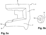
- the extensions 9 may be perforated, as shown on the Figures 3a and 3b .
- Such an opening (15) allows for the same height of the extension to reduce its stiffness. It is indeed interesting that extensions 9 are the highest possible to present the largest possible support area against the bumper skin. However, too high a height may cause too much stiffness, it then becomes possible to modulate this stiffness by a journeying.
- the assembly formed by the lower part 7 and the extensions 9 extends over a length greater than that of the upper part 5 in the longitudinal direction of the vehicle, so that there remains a spacing between the end distal of the upper part 5 and the bumper skin 13.
- the bumper skin facing the upper part 5 may be deformed and will not impede the rotation of the knee. Therefore the pedestrian's leg can be lying towards the hood of the vehicle.
- the upper part 5 must not be too far back from the skin 13 of the bumper, in part to prevent the latter from being too deformed, and secondly to absorb quickly the energy from the shock.
- the assembly formed by the lower part 7 and by the extensions 9 has a length greater than the length of the upper part 5, the difference in length being between 5 mm to 15 mm, preferably the difference in length is 10 mm.
- the base and the lower 7 and upper 5 parts have a profile in the form of "C" and the lower 7 and upper 5 have the same length.
- the device 1 shows near or identical shock absorption capacities in the upper and lower parts.
- the base and the lower and upper parts have a profile shaped "C" and the configuration of the lower part 7 is thicker than the upper part 5. This difference thickness of the upper and lower parts makes it possible to generate a difference in stiffness of these two parts formed in the same material.
- the bumper system may furthermore comprise a lower bumper beam 11 called a "lower track" at the central deflector, as shown in FIG. figure 2 .
- the lower bumper beam 11 preferably extends over a length greater than that of the upper part 5 and the lower part 7 in the longitudinal direction of the vehicle. In this way, during a shock with the leg of a pedestrian, it will be easier to lie down.
- the absorption device 1 comprises a plurality of extensions 9 distributed in the transverse direction of the vehicle on the distal end of the lower part 7 and arranged spaced apart from each other.
- each extension is a straight cylinder forming a pawn.
- the pins have a diameter smaller than the height of the lower part 7 depending on the height of the vehicle.
- each extension 9 can be modulated to play on the deformation of the bumper skin. In this case the more extensions 9 as well as the more these extensions 9 have dimensions reduced compared to the lower part 7, the more the bumper skin can be deformed. It is thus possible to obtain flexibility and rigidity that can be adjusted according to the desired needs.
- the base and the lower and upper parts of the absorption device 1 are formed of a foam chosen from a polyether, polyester, polypropylene, polyethylene or polyurethane foam, preferably made of polyethylene foam.
- the foam may be an expanded polyethylene foam of NEOPOLEN® type.
- the extensions are of a material having a lower rigidity than the material of the lower part, these are either formed in the same foam as the lower part but with a lower density or in a foam with a lower rigidity.
- the extensions 9 are integral with the lower part 7 as shown in FIG. figure 3a .
- the upper part of the absorption device is integral with the one or more extensions and is formed of a material having a lower rigidity to the material forming the lower part, and the part upper is dimensioned to extend over a length greater than that of the lower part in the longitudinal direction of the vehicle so as to dock the bumper skin.
- the profile of the absorption device is preferably solid, without central recess.
- the upper part is in contact with the bumper skin, which allows it to ensure the holding of the bumper skin in the upper part of the absorption device and therefore increases the holding of the skin of bumper shocks by the absorption device.
- the stiffness of the assembly formed by the upper part and the extension or extensions is less than that of the lower part and thus ensures the sleeping of the leg of the pedestrian during impact.
- the lower and upper parts are each formed of a foam of either different materials or similar materials but having a different density so that the density of the foam forming the upper part and the one or the extensions is lower the density of the foam forming the upper part.
Landscapes
- Engineering & Computer Science (AREA)
- Mechanical Engineering (AREA)
- Vibration Dampers (AREA)
Claims (3)
- Fahrzeug, das ein Frontstoßfängersystem umfasst, das einen Balken, eine Stoßfängerauskleidung (13) und eine Stoßabsorptionsvorrichtung (1), die zwischen dem Balken und der Stoßfängerauskleidung (13) angeordnet ist, umfasst; wobei die Absorptionsvorrichtung (1)- eine vertikale Basis (3), die gegen den Balken platziert ist;- einen oberen Teil (5) und einen unteren Teil (7) umfasst, die sich horizontal ausgehend von der Basis (3) in Richtung der Vorderseite des Fahrzeugs erstrecken, wobei der obere Teil (5) oberhalb des unteren Teils (7) positioniert ist, wobei der obere Teil (5) entweder bemessen ist, damit ein Abstand zwischen seinem distalen Ende und der Stoßfängerauskleidung (13) verbleibt, oder aus einem Material gebildet ist, das eine Steifigkeit aufweist, die kleiner ist als die des Materials, das den unteren Teil (7) bildet, Fahrzeug dadurch gekennzeichnet, dass die Absorptionsvorrichtung (1) mindestens eine Erweiterung (9) umfasst, die sich in der Verlängerung des distalen Endes des unteren Teils (7) erstreckt und bemessen ist, um an die Stoßfängerauskleidung (13) anzudocken, und dass die Absorptionsvorrichtung (1) außerdem eine Mehrzahl von Erweiterungen (9) in Form von Klötzen umfasst, die aus einem Stück mit dem unteren Teil (7) gebildet sind, die entlang der Querrichtung des Fahrzeugs auf dem distalen Ende des unteren Teils (7) verteilt und voneinander beabstandet angeordnet sind.
- Fahrzeug nach Anspruch 1, wobei der obere Teil (5) bemessen ist, damit ein Abstand zwischen seinem distalen Ende und der Stoßfängerauskleidung (13) verbleibt, dadurch gekennzeichnet, dass die Stoßabsorptionsvorrichtung (1) ein Profil in C-Form aufweist, und dass die Baugruppe, die aus dem unteren Teil (7) und den Erweiterungen (9) gebildet ist, eine Länge aufweist, die größer ist als die Länge des oberen Teils (5), wobei der Längenunterschied zwischen 5 mm und 15 mm liegt.
- Fahrzeug nach einem der Ansprüche 1 bis 2, dadurch gekennzeichnet, dass die Basis (3) und die unteren (7) und oberen (5) Teile der Absorptionsvorrichtung (1) aus einem Stück bestehen und aus einem Schaumstoff gebildet sind, der aus einem Polyether-, Polyester-, Polypropylen-, Polyethylen-oder Polyurethanschaumstoff, bevorzugt aus Polyethylenschaumstoff, ausgewählt ist.
Applications Claiming Priority (1)
| Application Number | Priority Date | Filing Date | Title |
|---|---|---|---|
| FR1659377A FR3056507A1 (fr) | 2016-09-29 | 2016-09-29 | Vehicule comprenant un dispositif d’absorption de chocs |
Publications (2)
| Publication Number | Publication Date |
|---|---|
| EP3300963A1 EP3300963A1 (de) | 2018-04-04 |
| EP3300963B1 true EP3300963B1 (de) | 2019-05-15 |
Family
ID=57539450
Family Applications (1)
| Application Number | Title | Priority Date | Filing Date |
|---|---|---|---|
| EP17187279.9A Active EP3300963B1 (de) | 2016-09-29 | 2017-08-22 | Fahrzeug, das eine stossdämpfende vorrichtung umfasst |
Country Status (3)
| Country | Link |
|---|---|
| EP (1) | EP3300963B1 (de) |
| CN (1) | CN107878374A (de) |
| FR (1) | FR3056507A1 (de) |
Cited By (2)
| Publication number | Priority date | Publication date | Assignee | Title |
|---|---|---|---|---|
| FR3141411A1 (fr) * | 2022-10-28 | 2024-05-03 | Psa Automobiles Sa | Absorbeur de pare-chocs avec bossages intégrés pour véhicule automobile |
| WO2025003587A1 (fr) | 2023-06-28 | 2025-01-02 | Stellantis Auto Sas | Vehicule avec systeme d'absorption de chocs avant comprenant des absorbeurs lateraux |
Families Citing this family (1)
| Publication number | Priority date | Publication date | Assignee | Title |
|---|---|---|---|---|
| CN110871761B (zh) * | 2018-08-31 | 2024-05-14 | 标致雪铁龙汽车股份有限公司 | 一种车辆前保险杠骨架结构及车辆 |
Family Cites Families (19)
| Publication number | Priority date | Publication date | Assignee | Title |
|---|---|---|---|---|
| DE69904140T2 (de) * | 1999-04-24 | 2003-08-21 | Ford Global Technologies, Inc. | Kraftfahrzeugstossfänger mit optimalen mechanischen Eigenschaften zum Verbessern des Fussgängerschutzes |
| JP2001277963A (ja) * | 2000-03-30 | 2001-10-10 | Fuji Heavy Ind Ltd | 自動車用バンパ構造 |
| US6685243B1 (en) * | 2002-07-30 | 2004-02-03 | Shape Corporation | Bumper for reducing pedestrian injury |
| JP2004196156A (ja) * | 2002-12-19 | 2004-07-15 | Calsonic Kansei Corp | 自動車の車体前部構造 |
| ATE471846T1 (de) * | 2003-07-03 | 2010-07-15 | Netshape Energy Man Llc | Stossfängersystem mit thermogeformtem energieaufnehmer |
| JP2005306161A (ja) * | 2004-04-20 | 2005-11-04 | Asteer Co Ltd | バンパ装置 |
| JP4434096B2 (ja) * | 2005-07-11 | 2010-03-17 | トヨタ自動車株式会社 | バンパ構造 |
| JP2007204017A (ja) * | 2006-02-06 | 2007-08-16 | Fuji Heavy Ind Ltd | 衝撃吸収部材およびそれを用いた車両用バンパ構造 |
| JP4317203B2 (ja) * | 2006-06-13 | 2009-08-19 | 小島プレス工業株式会社 | 車両用歩行者保護装置 |
| JP5251289B2 (ja) * | 2007-08-10 | 2013-07-31 | 日産自動車株式会社 | エネルギー吸収部材および車両用バンパ |
| CN201291825Y (zh) * | 2008-09-09 | 2009-08-19 | 上海通用汽车有限公司 | 一种新型行人腿部保护装置 |
| JP5254828B2 (ja) * | 2009-02-02 | 2013-08-07 | 富士重工業株式会社 | 衝撃吸収部材及び車両用バンパ構造 |
| KR20110049297A (ko) * | 2009-11-05 | 2011-05-12 | 현대자동차주식회사 | 보행자 다리 상해 저감용 로워 스티프너가 구비된 프런트 범퍼레일 |
| US8196979B2 (en) * | 2009-11-06 | 2012-06-12 | Shape Corp. | Energy absorber with lobes providing uniform pedestrian impact |
| US9033380B2 (en) * | 2012-05-23 | 2015-05-19 | Sabic Global Technologies B.V. | Energy absorber with staggered, vertically oriented crush lobes |
| CN202783042U (zh) * | 2012-07-02 | 2013-03-13 | 北京汽车股份有限公司 | 一种保险杠系统及汽车 |
| JP6131837B2 (ja) * | 2013-11-15 | 2017-05-24 | マツダ株式会社 | 車両の前部構造 |
| US9902351B2 (en) * | 2014-03-31 | 2018-02-27 | SABIC Global Technologies B.V | Hybrid bumper beams and methods for making and using the same |
| US9327662B1 (en) * | 2014-11-24 | 2016-05-03 | Toyota Motor Engineering & Manufacturing North America, Inc. | Bumper assemblies including lower reinforcement members |
-
2016
- 2016-09-29 FR FR1659377A patent/FR3056507A1/fr not_active Withdrawn
-
2017
- 2017-08-22 EP EP17187279.9A patent/EP3300963B1/de active Active
- 2017-09-29 CN CN201710909051.XA patent/CN107878374A/zh active Pending
Non-Patent Citations (1)
| Title |
|---|
| None * |
Cited By (3)
| Publication number | Priority date | Publication date | Assignee | Title |
|---|---|---|---|---|
| FR3141411A1 (fr) * | 2022-10-28 | 2024-05-03 | Psa Automobiles Sa | Absorbeur de pare-chocs avec bossages intégrés pour véhicule automobile |
| WO2025003587A1 (fr) | 2023-06-28 | 2025-01-02 | Stellantis Auto Sas | Vehicule avec systeme d'absorption de chocs avant comprenant des absorbeurs lateraux |
| FR3150487A1 (fr) | 2023-06-28 | 2025-01-03 | Psa Automobiles Sa | Vehicule avec systeme d’absorption de chocs avant comprenant des absorbeurs lateraux |
Also Published As
| Publication number | Publication date |
|---|---|
| FR3056507A1 (fr) | 2018-03-30 |
| EP3300963A1 (de) | 2018-04-04 |
| CN107878374A (zh) | 2018-04-06 |
Similar Documents
| Publication | Publication Date | Title |
|---|---|---|
| EP3300963B1 (de) | Fahrzeug, das eine stossdämpfende vorrichtung umfasst | |
| EP0802100A1 (de) | Schienenfahrzeug mit einem Fahrerstand, der eine energieaufnehmende Struktur mit progressiver Verformung aufweist | |
| EP1422110B1 (de) | Autostossfänger mit einem komprimierbarem Block der einen zunehmenden Querschnitt hat | |
| FR2959465A1 (fr) | Piece de carrosserie de vehicule automobile et structure d'extremite de vehicule automobile comprenant une telle piece. | |
| EP2532787B1 (de) | Sicherheitsschranke für Fahrbahnen, und Verfahren zur Verbesserung der Energieabsorption beim Aufprall eines leichten Fahrzeugs gegen eine solche Schranke | |
| EP4263295B1 (de) | Stossfängervorrichtung mit integriertem absorber und fahrzeug mit dieser vorrichtung | |
| FR3041580A1 (fr) | Structure de vehicule comportant un dispositif de renfort et vehicule comportant une telle structure | |
| WO1997041308A1 (fr) | Dispositif attenuateur de choc dispose en bordure d'une voie de circulation pour vehicule automobile | |
| WO2008061824A1 (fr) | Ensemble d'absorption de chocs pour vehicule automobile et face avant correspondante | |
| EP3630552B1 (de) | Frontteil der karosserie eines fahrzeugs mit seitenverstärkungen für den fall eines frontalzusammenstosses mit einem anderen fahrzeug | |
| EP0999310A1 (de) | Leitplanken für Fahrbahnen, mit zwei übereinander angeordneten Holmen mit differentiellem Eindringungswiderstand | |
| EP4071001B1 (de) | Stossabsorber aus schaumstoff für kraftfahrzeug | |
| WO2018185388A1 (fr) | Poutre centrale pour chassis arriere de vehicule comprenant en partie arriere un profile de renfort | |
| FR2810940A1 (fr) | Bloc avant comprenant des elements d'absorption d'energie de choc et vehicule automobile correspondant | |
| FR3018493A1 (fr) | Partie avant de la caisse d'un vehicule equipee d'une traverse convexe a poussee laterale en cas de chocs frontaux contre un mur rigide | |
| EP2112028B1 (de) | Absorber für Kraftfahrzeug | |
| EP3500455B1 (de) | Hinterer schalldämpfer für ein kraftfahrzeug | |
| FR3135676A1 (fr) | DISPOSITIF ALLÉGÉ D’ABSORPTION DES CHOCS pour VÉHICULES AUTOMOBILES | |
| EP4001060B1 (de) | Frontstruktur eines kraftfahrzeugs mit frontalaufprallsteuerung mit geringer abdeckung | |
| EP3199409B1 (de) | Formelement eines belüftungsgitters für die frontseite eines kraftfahrzeugs | |
| FR3125490A1 (fr) | Véhicule automobile avec une structure de caisse comportant un pare-chocs avant | |
| FR3144802A1 (fr) | Déflecteur de véhicule automobile comprenant des alvéoles déformables | |
| FR3151997A1 (fr) | Dispositif de securite passive d’au moins une zone crosse de pare-chocs de vehicule | |
| WO2016097592A1 (fr) | Berceau d'un véhicule automobile | |
| FR3039109B1 (fr) | Vehicule comportant un element de blocage d’une roue directionnelle |
Legal Events
| Date | Code | Title | Description |
|---|---|---|---|
| PUAI | Public reference made under article 153(3) epc to a published international application that has entered the european phase |
Free format text: ORIGINAL CODE: 0009012 |
|
| STAA | Information on the status of an ep patent application or granted ep patent |
Free format text: STATUS: THE APPLICATION HAS BEEN PUBLISHED |
|
| AK | Designated contracting states |
Kind code of ref document: A1 Designated state(s): AL AT BE BG CH CY CZ DE DK EE ES FI FR GB GR HR HU IE IS IT LI LT LU LV MC MK MT NL NO PL PT RO RS SE SI SK SM TR |
|
| AX | Request for extension of the european patent |
Extension state: BA ME |
|
| STAA | Information on the status of an ep patent application or granted ep patent |
Free format text: STATUS: REQUEST FOR EXAMINATION WAS MADE |
|
| 17P | Request for examination filed |
Effective date: 20181004 |
|
| RBV | Designated contracting states (corrected) |
Designated state(s): AL AT BE BG CH CY CZ DE DK EE ES FI FR GB GR HR HU IE IS IT LI LT LU LV MC MK MT NL NO PL PT RO RS SE SI SK SM TR |
|
| GRAP | Despatch of communication of intention to grant a patent |
Free format text: ORIGINAL CODE: EPIDOSNIGR1 |
|
| STAA | Information on the status of an ep patent application or granted ep patent |
Free format text: STATUS: GRANT OF PATENT IS INTENDED |
|
| INTG | Intention to grant announced |
Effective date: 20181211 |
|
| GRAS | Grant fee paid |
Free format text: ORIGINAL CODE: EPIDOSNIGR3 |
|
| GRAA | (expected) grant |
Free format text: ORIGINAL CODE: 0009210 |
|
| STAA | Information on the status of an ep patent application or granted ep patent |
Free format text: STATUS: THE PATENT HAS BEEN GRANTED |
|
| AK | Designated contracting states |
Kind code of ref document: B1 Designated state(s): AL AT BE BG CH CY CZ DE DK EE ES FI FR GB GR HR HU IE IS IT LI LT LU LV MC MK MT NL NO PL PT RO RS SE SI SK SM TR |
|
| REG | Reference to a national code |
Ref country code: CH Ref legal event code: EP |
|
| REG | Reference to a national code |
Ref country code: DE Ref legal event code: R084 Ref document number: 602017003895 Country of ref document: DE |
|
| REG | Reference to a national code |
Ref country code: IE Ref legal event code: FG4D Free format text: LANGUAGE OF EP DOCUMENT: FRENCH |
|
| REG | Reference to a national code |
Ref country code: DE Ref legal event code: R096 Ref document number: 602017003895 Country of ref document: DE |
|
| REG | Reference to a national code |
Ref country code: GB Ref legal event code: 746 Effective date: 20190617 |
|
| REG | Reference to a national code |
Ref country code: NL Ref legal event code: MP Effective date: 20190515 |
|
| REG | Reference to a national code |
Ref country code: LT Ref legal event code: MG4D |
|
| PG25 | Lapsed in a contracting state [announced via postgrant information from national office to epo] |
Ref country code: SE Free format text: LAPSE BECAUSE OF FAILURE TO SUBMIT A TRANSLATION OF THE DESCRIPTION OR TO PAY THE FEE WITHIN THE PRESCRIBED TIME-LIMIT Effective date: 20190515 Ref country code: NL Free format text: LAPSE BECAUSE OF FAILURE TO SUBMIT A TRANSLATION OF THE DESCRIPTION OR TO PAY THE FEE WITHIN THE PRESCRIBED TIME-LIMIT Effective date: 20190515 Ref country code: LT Free format text: LAPSE BECAUSE OF FAILURE TO SUBMIT A TRANSLATION OF THE DESCRIPTION OR TO PAY THE FEE WITHIN THE PRESCRIBED TIME-LIMIT Effective date: 20190515 Ref country code: ES Free format text: LAPSE BECAUSE OF FAILURE TO SUBMIT A TRANSLATION OF THE DESCRIPTION OR TO PAY THE FEE WITHIN THE PRESCRIBED TIME-LIMIT Effective date: 20190515 Ref country code: FI Free format text: LAPSE BECAUSE OF FAILURE TO SUBMIT A TRANSLATION OF THE DESCRIPTION OR TO PAY THE FEE WITHIN THE PRESCRIBED TIME-LIMIT Effective date: 20190515 Ref country code: AL Free format text: LAPSE BECAUSE OF FAILURE TO SUBMIT A TRANSLATION OF THE DESCRIPTION OR TO PAY THE FEE WITHIN THE PRESCRIBED TIME-LIMIT Effective date: 20190515 Ref country code: NO Free format text: LAPSE BECAUSE OF FAILURE TO SUBMIT A TRANSLATION OF THE DESCRIPTION OR TO PAY THE FEE WITHIN THE PRESCRIBED TIME-LIMIT Effective date: 20190815 Ref country code: PT Free format text: LAPSE BECAUSE OF FAILURE TO SUBMIT A TRANSLATION OF THE DESCRIPTION OR TO PAY THE FEE WITHIN THE PRESCRIBED TIME-LIMIT Effective date: 20190915 Ref country code: HR Free format text: LAPSE BECAUSE OF FAILURE TO SUBMIT A TRANSLATION OF THE DESCRIPTION OR TO PAY THE FEE WITHIN THE PRESCRIBED TIME-LIMIT Effective date: 20190515 |
|
| PG25 | Lapsed in a contracting state [announced via postgrant information from national office to epo] |
Ref country code: GR Free format text: LAPSE BECAUSE OF FAILURE TO SUBMIT A TRANSLATION OF THE DESCRIPTION OR TO PAY THE FEE WITHIN THE PRESCRIBED TIME-LIMIT Effective date: 20190816 Ref country code: LV Free format text: LAPSE BECAUSE OF FAILURE TO SUBMIT A TRANSLATION OF THE DESCRIPTION OR TO PAY THE FEE WITHIN THE PRESCRIBED TIME-LIMIT Effective date: 20190515 Ref country code: BG Free format text: LAPSE BECAUSE OF FAILURE TO SUBMIT A TRANSLATION OF THE DESCRIPTION OR TO PAY THE FEE WITHIN THE PRESCRIBED TIME-LIMIT Effective date: 20190815 Ref country code: RS Free format text: LAPSE BECAUSE OF FAILURE TO SUBMIT A TRANSLATION OF THE DESCRIPTION OR TO PAY THE FEE WITHIN THE PRESCRIBED TIME-LIMIT Effective date: 20190515 |
|
| REG | Reference to a national code |
Ref country code: AT Ref legal event code: MK05 Ref document number: 1133050 Country of ref document: AT Kind code of ref document: T Effective date: 20190515 |
|
| PG25 | Lapsed in a contracting state [announced via postgrant information from national office to epo] |
Ref country code: DK Free format text: LAPSE BECAUSE OF FAILURE TO SUBMIT A TRANSLATION OF THE DESCRIPTION OR TO PAY THE FEE WITHIN THE PRESCRIBED TIME-LIMIT Effective date: 20190515 Ref country code: AT Free format text: LAPSE BECAUSE OF FAILURE TO SUBMIT A TRANSLATION OF THE DESCRIPTION OR TO PAY THE FEE WITHIN THE PRESCRIBED TIME-LIMIT Effective date: 20190515 Ref country code: EE Free format text: LAPSE BECAUSE OF FAILURE TO SUBMIT A TRANSLATION OF THE DESCRIPTION OR TO PAY THE FEE WITHIN THE PRESCRIBED TIME-LIMIT Effective date: 20190515 Ref country code: CZ Free format text: LAPSE BECAUSE OF FAILURE TO SUBMIT A TRANSLATION OF THE DESCRIPTION OR TO PAY THE FEE WITHIN THE PRESCRIBED TIME-LIMIT Effective date: 20190515 Ref country code: SK Free format text: LAPSE BECAUSE OF FAILURE TO SUBMIT A TRANSLATION OF THE DESCRIPTION OR TO PAY THE FEE WITHIN THE PRESCRIBED TIME-LIMIT Effective date: 20190515 |
|
| REG | Reference to a national code |
Ref country code: DE Ref legal event code: R097 Ref document number: 602017003895 Country of ref document: DE |
|
| PG25 | Lapsed in a contracting state [announced via postgrant information from national office to epo] |
Ref country code: SM Free format text: LAPSE BECAUSE OF FAILURE TO SUBMIT A TRANSLATION OF THE DESCRIPTION OR TO PAY THE FEE WITHIN THE PRESCRIBED TIME-LIMIT Effective date: 20190515 Ref country code: IT Free format text: LAPSE BECAUSE OF FAILURE TO SUBMIT A TRANSLATION OF THE DESCRIPTION OR TO PAY THE FEE WITHIN THE PRESCRIBED TIME-LIMIT Effective date: 20190515 |
|
| PLBE | No opposition filed within time limit |
Free format text: ORIGINAL CODE: 0009261 |
|
| STAA | Information on the status of an ep patent application or granted ep patent |
Free format text: STATUS: NO OPPOSITION FILED WITHIN TIME LIMIT |
|
| PG25 | Lapsed in a contracting state [announced via postgrant information from national office to epo] |
Ref country code: TR Free format text: LAPSE BECAUSE OF FAILURE TO SUBMIT A TRANSLATION OF THE DESCRIPTION OR TO PAY THE FEE WITHIN THE PRESCRIBED TIME-LIMIT Effective date: 20190515 |
|
| 26N | No opposition filed |
Effective date: 20200218 |
|
| PG25 | Lapsed in a contracting state [announced via postgrant information from national office to epo] |
Ref country code: PL Free format text: LAPSE BECAUSE OF FAILURE TO SUBMIT A TRANSLATION OF THE DESCRIPTION OR TO PAY THE FEE WITHIN THE PRESCRIBED TIME-LIMIT Effective date: 20190515 |
|
| PG25 | Lapsed in a contracting state [announced via postgrant information from national office to epo] |
Ref country code: MC Free format text: LAPSE BECAUSE OF FAILURE TO SUBMIT A TRANSLATION OF THE DESCRIPTION OR TO PAY THE FEE WITHIN THE PRESCRIBED TIME-LIMIT Effective date: 20190515 Ref country code: SI Free format text: LAPSE BECAUSE OF FAILURE TO SUBMIT A TRANSLATION OF THE DESCRIPTION OR TO PAY THE FEE WITHIN THE PRESCRIBED TIME-LIMIT Effective date: 20190515 Ref country code: LU Free format text: LAPSE BECAUSE OF NON-PAYMENT OF DUE FEES Effective date: 20190822 |
|
| REG | Reference to a national code |
Ref country code: BE Ref legal event code: MM Effective date: 20190831 |
|
| PG25 | Lapsed in a contracting state [announced via postgrant information from national office to epo] |
Ref country code: IE Free format text: LAPSE BECAUSE OF NON-PAYMENT OF DUE FEES Effective date: 20190822 |
|
| PG25 | Lapsed in a contracting state [announced via postgrant information from national office to epo] |
Ref country code: BE Free format text: LAPSE BECAUSE OF NON-PAYMENT OF DUE FEES Effective date: 20190831 |
|
| REG | Reference to a national code |
Ref country code: CH Ref legal event code: PL |
|
| PG25 | Lapsed in a contracting state [announced via postgrant information from national office to epo] |
Ref country code: CH Free format text: LAPSE BECAUSE OF NON-PAYMENT OF DUE FEES Effective date: 20200831 Ref country code: RO Free format text: LAPSE BECAUSE OF FAILURE TO SUBMIT A TRANSLATION OF THE DESCRIPTION OR TO PAY THE FEE WITHIN THE PRESCRIBED TIME-LIMIT Effective date: 20190515 Ref country code: LI Free format text: LAPSE BECAUSE OF NON-PAYMENT OF DUE FEES Effective date: 20200831 |
|
| PG25 | Lapsed in a contracting state [announced via postgrant information from national office to epo] |
Ref country code: CY Free format text: LAPSE BECAUSE OF FAILURE TO SUBMIT A TRANSLATION OF THE DESCRIPTION OR TO PAY THE FEE WITHIN THE PRESCRIBED TIME-LIMIT Effective date: 20190515 |
|
| PG25 | Lapsed in a contracting state [announced via postgrant information from national office to epo] |
Ref country code: IS Free format text: LAPSE BECAUSE OF FAILURE TO SUBMIT A TRANSLATION OF THE DESCRIPTION OR TO PAY THE FEE WITHIN THE PRESCRIBED TIME-LIMIT Effective date: 20190915 |
|
| PG25 | Lapsed in a contracting state [announced via postgrant information from national office to epo] |
Ref country code: HU Free format text: LAPSE BECAUSE OF FAILURE TO SUBMIT A TRANSLATION OF THE DESCRIPTION OR TO PAY THE FEE WITHIN THE PRESCRIBED TIME-LIMIT; INVALID AB INITIO Effective date: 20170822 Ref country code: MT Free format text: LAPSE BECAUSE OF FAILURE TO SUBMIT A TRANSLATION OF THE DESCRIPTION OR TO PAY THE FEE WITHIN THE PRESCRIBED TIME-LIMIT Effective date: 20190515 |
|
| PG25 | Lapsed in a contracting state [announced via postgrant information from national office to epo] |
Ref country code: MK Free format text: LAPSE BECAUSE OF FAILURE TO SUBMIT A TRANSLATION OF THE DESCRIPTION OR TO PAY THE FEE WITHIN THE PRESCRIBED TIME-LIMIT Effective date: 20190515 |
|
| REG | Reference to a national code |
Ref country code: DE Ref legal event code: R081 Ref document number: 602017003895 Country of ref document: DE Owner name: STELLANTIS AUTO SAS, FR Free format text: FORMER OWNER: PSA AUTOMOBILES SA, POISSY, FR |
|
| PGFP | Annual fee paid to national office [announced via postgrant information from national office to epo] |
Ref country code: DE Payment date: 20250724 Year of fee payment: 9 |
|
| PGFP | Annual fee paid to national office [announced via postgrant information from national office to epo] |
Ref country code: GB Payment date: 20250724 Year of fee payment: 9 |
|
| PGFP | Annual fee paid to national office [announced via postgrant information from national office to epo] |
Ref country code: FR Payment date: 20250725 Year of fee payment: 9 |