EP3300975A1 - Dispositif de freinage pour un véhicule destiné au transport de charges lourdes, véhicule destiné au transport de charges lourdes et procédé d'augmentation de la puissance de freinage d'un véhicule destiné au transport de charges lourdes - Google Patents
Dispositif de freinage pour un véhicule destiné au transport de charges lourdes, véhicule destiné au transport de charges lourdes et procédé d'augmentation de la puissance de freinage d'un véhicule destiné au transport de charges lourdes Download PDFInfo
- Publication number
- EP3300975A1 EP3300975A1 EP17020445.7A EP17020445A EP3300975A1 EP 3300975 A1 EP3300975 A1 EP 3300975A1 EP 17020445 A EP17020445 A EP 17020445A EP 3300975 A1 EP3300975 A1 EP 3300975A1
- Authority
- EP
- European Patent Office
- Prior art keywords
- pressure medium
- heavy
- duty vehicle
- braking device
- braking
- Prior art date
- Legal status (The legal status is an assumption and is not a legal conclusion. Google has not performed a legal analysis and makes no representation as to the accuracy of the status listed.)
- Granted
Links
Images


Classifications
-
- B—PERFORMING OPERATIONS; TRANSPORTING
- B60—VEHICLES IN GENERAL
- B60T—VEHICLE BRAKE CONTROL SYSTEMS OR PARTS THEREOF; BRAKE CONTROL SYSTEMS OR PARTS THEREOF, IN GENERAL; ARRANGEMENT OF BRAKING ELEMENTS ON VEHICLES IN GENERAL; PORTABLE DEVICES FOR PREVENTING UNWANTED MOVEMENT OF VEHICLES; VEHICLE MODIFICATIONS TO FACILITATE COOLING OF BRAKES
- B60T10/00—Control or regulation for continuous braking making use of fluid or powdered medium, e.g. for use when descending a long slope
- B60T10/02—Control or regulation for continuous braking making use of fluid or powdered medium, e.g. for use when descending a long slope with hydrodynamic brake
Definitions
- the invention relates to a braking device for a heavy-duty vehicle, in particular a self-propelled heavy-duty vehicle having a chassis with a number of wheel assemblies with wheel motors to which a pressure medium provided by a drive device via pressure lines of at least one pressure medium circuit is supplied, said pressure medium after the Flowing through the one or more wheel motors is fed back via further pressure lines to the drive device, a braking device using this heavy-duty vehicle and a method for increasing the braking performance of a heavy-duty vehicle.
- Such vehicles are known and used in the heavy load area for the transport of heavy and / or bulky loads.
- self-propelled vehicles are used for this purpose, which have a drive device or are coupled to a drive device which generates the drive energy required for driving the wheel arrangements.
- Such a drive device is known from DE 10 2010 023 307 A1 the applicant known.
- a drive device for a self-propelled heavy-duty vehicle which comprises a drive unit with an internal combustion engine, which drives a pump arrangement for generating a hydraulic pressure. About one or more pressure lines pressurized by the drive unit pressure medium is passed to the heavy-duty vehicle and drives there hydraulic wheel motors of the wheel assemblies of the heavy-duty vehicle.
- Such self-propelled, hydraulically powered heavy-duty vehicles have been mainly in limited areas such. In factories, shipyards, ports, to name but a few, used to transport heavy loads over relatively short distances without major gradients.
- the retarder is arranged downstream of the manual or automatic transmission of the commercial vehicle and an input of the retarder is mechanically connected to an output of this transmission.
- a drive shaft of the commercial vehicle At an output of the retarder is a drive shaft of the commercial vehicle, which is mechanically connected to the rear axle.
- a hydrostatic drive system for a mobile work machine in particular an industrial truck, known, which has a hydrostatic drive and a working hydraulics.
- an axial piston pump is provided, which is used in the braking operation of the traction drive as a retarder pump and thus is used as a load unit, the additional support torque for deceleration generates the work machine and thus an excessive increase in the rotational speed of the drive system driving an internal combustion engine, which drives the axial piston pump of the working hydraulics and a pump of the traction drive, counteracts.
- the axial force acting as a retarder brake pump in braking mode is thus driven here by the internal combustion engine of the vehicle. So it is again arranged in the mechanical drive train.
- the DE 39 36 735 A1 shows a braking power converter for installation in self-propelled or towed road vehicles in the form of a mechanical friction independent, actuated by the thrust of the vehicle long-term brake having oil as working fluid and an oil kuhf adopted.
- This oil cooling device cools a hydraulic fluid serving as a heat carrier, preferably with the aid of the ambient air. It is envisaged that during the normal, unchecked run no oil flow flows and no piston pressure is created, so that virtually no flow performance occurs.
- a high-pressure piston pump is provided, which is arranged in a closed oil circuit, in which it is able to compress an oil flow to high pressure in braking mode, its energy in relaxation by controlled response of an arranged in the oil circuit pressure relief valve into heat implemented and discharged via the oil cooling device.
- the pressure relief valve is left at a fixed value.
- the braking power is controlled by means of the oil flow.
- the hydraulic pump is held directly to the wheels, so that in this way transmission part or the braking power are not claimed.
- the US 2,875,871 A shows a heavy duty vehicle using a throttle valve based hydrostatic retarder.
- the heavy-duty vehicle according to the invention is characterized in that it uses the braking device according to the invention.
- the inventive method for increasing the braking power for a heavy-duty vehicle suggests that the back-flowing pressure medium at least one pressure medium circuit is fed to a braking device, and that this braking device is designed according to one of claims 1 to 8.
- the inventive measures a braking device and a particularly suitable for this braking device heavy duty vehicle is formed in an advantageous manner, which are characterized in that in a simple manner, the heavy-duty vehicle available braking power is increased. Since only pressure hoses for coupling these two units are required between the driving device driving the heavy-duty vehicle and the braking device according to the invention, the retarder of the braking device according to the invention provided according to the invention can be flexibly installed.
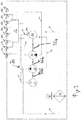
- FIG. 1 is shown schematically a generally designated 1 heavy-duty vehicle.
- the person skilled in the structural design and operation of such a heavy-duty vehicle is known, so that they do not need to be described in detail.
- the heavy duty vehicle 1 has a chassis 2 supported by a number of wheel assemblies 3a-3d.
- a number of axle lines are shown, of which a first axle line 4a with four wheel arrangements 3a-3d and a second axle line 4b with four wheel arrangements 3a'-3d 'are shown by way of example in the figures.
- the individual wheel arrangements 3a-3d, 3a'-3d ' can be designed as Einzelrad- or Doppelradan kannen. An arrangement of several wheel arrangements on a common axis is possible.
- the drive energy required for operating the heavy-duty vehicle 1 is provided by a drive device 10.
- This has a motor 11, in particular an internal combustion engine, here in particular a diesel engine, which drives one or more pumps, in the case described here two pumps 12a, 12b, via a shaft 13.
- the pumps 12a, 12b serve to generate the hydraulic pressure required to drive the hydraulic wheel motors 5.
- Such a drive device 10 is - as already mentioned - in particular from the DE 10 2010 023 307 A1 therefore, it does not have to be described any further.
- a pressure medium output 13a of the first pump 12a is connected via a pressure line 14a to a first pressure medium outlet 15a of the drive device 10.
- a first pressure medium input 16a of the drive device 10 is connected via a further pressure line 17a to a pressure medium input 18a of the first pump 12a.
- a pressure medium output 13b of the second pump 12b is connected via a pressure line 14b to a second pressure medium outlet 15b of the drive device 10 and a further pressure line 17b leads from a second pressure medium input 16b of the drive device 10 to a pressure medium input 18b of the second pump 12b.
- the outputs 15a and 15b of the drive device 10 would now be connected to corresponding inputs 25a, 25b of the self-propelled heavy-duty vehicle 1 via corresponding pressure lines and outputs 26a, 26b of the heavy-duty vehicle 1 via further pressure lines to the corresponding inputs 16a. 16b of the drive device 10, so that a generated by the first pump 12 a pressure medium over the first pressure medium output 15a drive device 10 which is passed to the pressure medium input 25a of the heavy-duty vehicle 1.
- the fluid flowing back from the wheel motors 5 pressure medium would be passed via the first pressure line to the pressure medium output 26a of the heavy-duty vehicle 1 and would then be directed via a corresponding further pressure line to the first pressure medium input 16a of the drive device 10.
- the pressure medium applied to the second pressure medium output 15b of the drive device 10 and conducted to the second pressure medium input 25b of the heavy-duty vehicle 1 would be conducted via the second pressure line to the wheel motors 5 of the heavy-duty vehicle 1.
- the flowing back from these wheel motors 5 pressure medium would be passed via a pressure line to the pressure medium output 26b of the heavy-duty vehicle 1 and then returned to the pressure medium input 16b in the known heavy-duty vehicles.
- the flow direction of the pressure medium in both of the above-defined pressure medium circuits of the two pumps 12a, 12b corresponds to those in the forward travel of the heavy-duty vehicle 1.
- a braking device 30 is connected between the drive device 10 and the heavy-duty vehicle 1, its structure and function is explained below.
- the operating principle of the braking device 30 described is based on it, in a retarder 80 (see FIG. 2 ) to convert hydraulic energy into heat and thus to destroy, which of the wheel motors 5, which act in overrun, so usually in the downhill, as so-called "secondary drive units" is generated.
- the braking power which can be used by the heavy-duty vehicle 1, is increased in an advantageous manner.
- the brake device 30 Since - as described below - the brake device 30 is connected only via pressure lines to the heavy-duty vehicle 1 and the drive device 10, a flexible installation of the same is advantageously made possible, the braking device 30 and thus the retarder 60 contained in it must therefore no longer - as is the case with known commercial vehicles - be arranged in the mechanical drive train between the combustion engine driving the heavy-duty vehicle 1 and the driven axle of the heavy-duty vehicle 1.
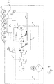
- the FIG. 2 Now shows a first embodiment of a braking device 30.
- the brake device 30 has a first pressure medium input 35a, which is connected via a pressure line 32a to the first pressure medium output 15a of the drive device 10.
- a first pressure medium output 36a of the brake device 30 is connected via a pressure line 37a to the pressure medium input 25a of the heavy-duty vehicle 1.
- the pressure medium output 26a of the heavy-duty vehicle 1 is connected via a pressure line 38a to a second pressure medium input 39a of the brake device 30.
- a pressure medium output 40 a of the brake device 30 is connected via a pressure line 41 a to the pressure medium input 16 a of the drive device 10.
- a driven by the first pump 12 a first pressure medium circuit is formed, which - as out FIG. 1 seen - the wheel motors 5 of the axis line 4b supplied with the appropriate pressure medium.
- the second pressure medium outlet 15b of the drive device 10 is connected via a pressure line 32b to a first pressure medium input 35b of the brake device 30.
- a pressure medium output 36b is connected via a pressure line 37b to the pressure medium input 25b of the heavy-duty vehicle 1.
- the pressure medium output 26b of the heavy-duty vehicle 1 is connected to a pressure line 35b with a second pressure medium input 39b of the second pressure medium circuit of the brake device 30.
- a pressure medium output 40b of the brake device 30 is connected via a pressure line 41b to the second pressure medium input 16b of the drive device 10.
- a driven by the second pump 12 b second pressure medium circuit is set, which supplies the wheel motors 5 of the first axis line 4 a with this driving pressure medium.
- two pressure medium circuits are formed, which in turn from corresponding outputs 15a and 15b via the brake device 30 to the corresponding inputs 25a and 25b of the heavy-duty vehicle 1 and via outputs 26a and 26b of the heavy-duty vehicle 1 again the brake device 30 back to the corresponding inputs 16a and 16b of the drive device 10 lead.
- the inputs 35a, 35b and 39a, 39b and the outputs 36a, 36b and 40a, 40b of the brake device 30 are each connected via a corresponding pressure line 43 to the control unit 50, so that - as described below - in the two pressure medium circuits flowing pressure medium as described below can be redirected.
- the control unit 50 makes it possible to operate the brake device 30 in two different operating modes, namely in a "normal mode” and in a "brake mode". If an increased braking power of the heavy-duty vehicle 1 is not required, the braking device 30 is operated in the first-mentioned "normal mode".
- the control unit 50 then directs the pressure medium input of the first pressure medium circuit applied to the pressure medium input 35a directly to the pressure medium outlet 36a.
- the flowing back in this first pressure fluid circuit pressure medium is from the pressure medium input 39a directly to the pressure medium output 40a of the brake device 30 and flows back via the pressure line 42a to the pressure medium input 16a of the drive device 10, so that a closed first pressure fluid circuit is formed.
- the above explanations apply to a drive of the heavy-duty vehicle 1 in the first direction of movement, that is to say in the forward direction, as a rule.
- the flow conditions reverse upon movement of the heavy duty vehicle 1 in the second direction of travel.
- the control unit 50 then, for example, forwards the pressure medium inlet 16a, which in this second direction of movement serves as the pressure medium outlet for the pressure medium of the first pressure medium circuit, to the pressure medium outlet 26a of the heavy duty vehicle 1 which now functions as the pressure medium inlet.
- the braking function of the braking device 30 is activated by z.
- the driver or operator of the heavy duty vehicle 1 actuates a corresponding button which causes the control unit 50 to be switched to its "brake mode".
- This has the effect that the refluxing pressure medium of the first and the second pressure medium circuit is no longer directly returned to the drive device 10, as described above. Rather, it is provided that the refluxing pressure medium of the two aforementioned pressure fluid circuits (at least partially) via a feed line 51 to a hydraulic motor 55 of the braking device 30 is guided, flows through it and then passed through a return line 52 to the control unit 50 and from this again - as described above - Is returned to the drive device 10.
- the hydraulic motor 55 drives the retarder 60 via a shaft 56.
- a retarder 60 is known per se and therefore need not be described in detail. Its effect is that it generates a braking effect by converting the rotational energy of the hydraulic motor 55 supplied to it, which is generated by the pressure fluid flowing through it, flowing back from the heavy-duty vehicle 1, into heat and thus destroyed.
- the wheel motors 5 act as secondary drive units in overrun mode, ie they generate energy in this operating mode which would drive the heavy-duty vehicle 1 - in this case undesirably.
- the heat energy generated in the retarder 60 is supplied to a coolant circuit 61, which has a coolant pump 62, which circulates the coolant circulating in the coolant circuit 61, in particular water.
- a cooler 63 is arranged, via which the heat stored in the coolant is discharged in a known manner to the environment.
- the cooler 63 is additionally cooled by a fan 64.
- the braking device 30 has a control unit 70 for the retarder 60, through which its braking power is controllable.
- a compressor 71 is used, which is driven directly or indirectly by the retarder 60, as shown here.
- the compressor 71 is connected via a line 72 to an actuator 73, whose pressure medium output is connected via a further line 74 to a control input 60a of the retarder 60.
- the control of the retarder 60 thus takes place here via compressed air generated by the compressor 71.
- the retarder in a different way, for. B. electrically, to control.
- the refluxing pressure medium of both the first and the second pressure medium circuit is guided to the hydraulic motor 55.
- Such a measure may, for. B. are then used when only a lower braking power of the braking device 30 is to be generated, but is not preferred.
- the hydraulic motor 55 drives the retarder 60 via a shaft 56 and the retarder 60 in turn is connected via the shaft 56 with the coolant pump 52 and the compressor 71.
- These secondary units of the brake device 30, ie (here) the hydraulic motor 55, the retarder 60, the coolant pump 55 and the compressor 71 are thus connected in series.
- FIG. 3 a second embodiment of a braking device 30 is shown. Corresponding components are provided with the same reference numerals and will not be described in detail. The essential difference between the first and the second embodiment is only to be seen in that the retarder 60 and the secondary units required for its operation, here the coolant pump 55 and the compressor 71 are no longer in Series are connected, but that it is provided that the hydraulic motor 55 via a first shaft portion 56a drives only the retarder 60 and a second shaft portion 56b, the aforementioned secondary units.
- FIG. 4 a third embodiment of a braking device 30 is shown, wherein corresponding components are described with the same reference numerals and will not be explained again.
- the essential difference between the first and the third embodiment is that the hydraulic motor 55 not only drives the secondary units needed to operate the retarder 60, but also that the hydraulic motor 55 also drives an attachment 80.
- This attachment 80 may be, for example, an electrical generator.
- Such a measure has the advantage that the excess energy, which is destroyed in the first two embodiments to produce the required braking power of the braking device 30, is converted by the attachment 80, into usable energy.
- the attachment 80 here an electric generator, thus z. B. Energy can be recovered.
- Such a measure has positive effects on the overall energy balance of such a heavy-duty vehicle 1.
- the heavy-duty vehicle 1 is a self-propelled heavy-duty vehicle 1 that is driven by a drive device 10 coupled to the heavy-duty vehicle 1.
- the measures described also apply, of course, to towed heavy-duty vehicles 1, that is to say heavy-duty vehicles 1 which are not driven by themselves but pulled by a towing vehicle.
- the braking device 30 is then switched between the trained as a trailer heavy-duty vehicle 1 and this trailer pulling and the drive device 10 having towing vehicle.
- the brake device 30 has only one retarder 60. Of course this is not mandatory. Rather, it is possible to provide more than one retarder. These two or more retarders 60 are then supplied by the described secondary units with the appropriate cooling medium. Of course, it is also possible that each of these retarder 60 has its own secondary aggregates. It is also possible to use more than one hydraulic motor 55.
- a braking device 30 and a particularly suitable for this braking device 30 heavy-duty vehicle 1 are formed, which are characterized in that in a simple manner the heavy-duty vehicle 1 available braking power is increased. Since only pressure hoses are required between the driving device 10 driving the heavy-duty vehicle 1 and this drive device for coupling the braking device 30, the braking device 30 and thus the retarder 60 can be installed flexibly.
Landscapes
- Engineering & Computer Science (AREA)
- Physics & Mathematics (AREA)
- Fluid Mechanics (AREA)
- Transportation (AREA)
- Mechanical Engineering (AREA)
- Regulating Braking Force (AREA)
- Transmission Of Braking Force In Braking Systems (AREA)
Applications Claiming Priority (2)
| Application Number | Priority Date | Filing Date | Title |
|---|---|---|---|
| DE102016011630.7A DE102016011630B4 (de) | 2016-09-28 | 2016-09-28 | Bremsvorrichtung für ein Schwerlast-Fahrzeug, Schwerlast-Fahrzeug und Verfahren zur Erhöhung der Bremsleistung eines Schwerlast-Fahrzeugs |
| DE202016005921.2U DE202016005921U1 (de) | 2016-09-28 | 2016-09-28 | Bremsvorrichtung für ein Schwerlast-Fahrzeug, insbesondere ein selbstangetriebenes Schwerlast-Fahrzeug |
Publications (2)
| Publication Number | Publication Date |
|---|---|
| EP3300975A1 true EP3300975A1 (fr) | 2018-04-04 |
| EP3300975B1 EP3300975B1 (fr) | 2018-11-28 |
Family
ID=59997027
Family Applications (1)
| Application Number | Title | Priority Date | Filing Date |
|---|---|---|---|
| EP17020445.7A Active EP3300975B1 (fr) | 2016-09-28 | 2017-09-27 | Dispositif de freinage pour un véhicule destiné au transport de charges lourdes, véhicule destiné au transport de charges lourdes et procédé d'augmentation de la puissance de freinage d'un véhicule destiné au transport de charges lourdes |
Country Status (1)
| Country | Link |
|---|---|
| EP (1) | EP3300975B1 (fr) |
Cited By (1)
| Publication number | Priority date | Publication date | Assignee | Title |
|---|---|---|---|---|
| WO2020200347A1 (fr) * | 2019-04-05 | 2020-10-08 | Suffel Fördertechnik GmbH & Co. KG | Dispositif et procédé pour le freinage d'un véhicule remorque |
Citations (6)
| Publication number | Priority date | Publication date | Assignee | Title |
|---|---|---|---|---|
| US2875871A (en) | 1955-09-26 | 1959-03-03 | Jaroco Engineering Co | Hydraulic system |
| DE3936735A1 (de) | 1989-11-04 | 1991-05-08 | Schaeff Karl Gmbh & Co | Hydrostatischer bremsleistungswandler |
| US5848664A (en) | 1993-10-29 | 1998-12-15 | Ec Engineering & Consulting Spezial-Maschinen Gmbh | Method and apparatus for hydrostatically driving a vehicle with each drivable wheel driven by at least one hydraulic motor connected to at least one hydraulic source |
| DE102009039829A1 (de) | 2009-09-02 | 2011-03-03 | Linde Material Handling Gmbh | Hydrostatische Axialkolbenpumpe, insbesondere Schrägscheibenpumpe |
| DE102010023307A1 (de) | 2010-06-10 | 2011-12-15 | Scheuerle Fahrzeugfabrik Gmbh | Antriebseinheit für ein modulares, selbstangetriebenes Schwerlastfahrzeug |
| WO2015185215A1 (fr) * | 2014-06-04 | 2015-12-10 | Scheuerle Fahrzeugfabrik Gmbh | Rame de véhicules comprenant plusieurs modules de véhicule entraînés |
-
2017
- 2017-09-27 EP EP17020445.7A patent/EP3300975B1/fr active Active
Patent Citations (6)
| Publication number | Priority date | Publication date | Assignee | Title |
|---|---|---|---|---|
| US2875871A (en) | 1955-09-26 | 1959-03-03 | Jaroco Engineering Co | Hydraulic system |
| DE3936735A1 (de) | 1989-11-04 | 1991-05-08 | Schaeff Karl Gmbh & Co | Hydrostatischer bremsleistungswandler |
| US5848664A (en) | 1993-10-29 | 1998-12-15 | Ec Engineering & Consulting Spezial-Maschinen Gmbh | Method and apparatus for hydrostatically driving a vehicle with each drivable wheel driven by at least one hydraulic motor connected to at least one hydraulic source |
| DE102009039829A1 (de) | 2009-09-02 | 2011-03-03 | Linde Material Handling Gmbh | Hydrostatische Axialkolbenpumpe, insbesondere Schrägscheibenpumpe |
| DE102010023307A1 (de) | 2010-06-10 | 2011-12-15 | Scheuerle Fahrzeugfabrik Gmbh | Antriebseinheit für ein modulares, selbstangetriebenes Schwerlastfahrzeug |
| WO2015185215A1 (fr) * | 2014-06-04 | 2015-12-10 | Scheuerle Fahrzeugfabrik Gmbh | Rame de véhicules comprenant plusieurs modules de véhicule entraînés |
Cited By (1)
| Publication number | Priority date | Publication date | Assignee | Title |
|---|---|---|---|---|
| WO2020200347A1 (fr) * | 2019-04-05 | 2020-10-08 | Suffel Fördertechnik GmbH & Co. KG | Dispositif et procédé pour le freinage d'un véhicule remorque |
Also Published As
| Publication number | Publication date |
|---|---|
| EP3300975B1 (fr) | 2018-11-28 |
Similar Documents
| Publication | Publication Date | Title |
|---|---|---|
| DE102016011630B4 (de) | Bremsvorrichtung für ein Schwerlast-Fahrzeug, Schwerlast-Fahrzeug und Verfahren zur Erhöhung der Bremsleistung eines Schwerlast-Fahrzeugs | |
| EP0427116B1 (fr) | Convertisseur d'énergie de freinage | |
| EP1224407B1 (fr) | Systeme ralentisseur | |
| EP3297884A1 (fr) | Procédé pour faire fonctionner un ensemble attelé, ensemble attelé, véhicule tracteur et engin de travail | |
| DE102004043304A1 (de) | Bremsvorrichtung | |
| EP0718166A2 (fr) | Unité d'entraînement à un moteur à combustion interne et un ralentisseur hydrodynamique | |
| DE102017202322A1 (de) | Verfahren zur Umsetzung einer fahrerseitigen Verzögerungsanforderung in eine Fahrzeugverzögerung beim Betrieb eines Elektrofahrzeugs sowie Elektrofahrzeug zur Durchführung des Verfahrens | |
| DE841850C (de) | Lastenfahrzeug oder Lastzug mit durch Fluessigkeitsmotoren angetriebenen Treibraedern | |
| EP3300975B1 (fr) | Dispositif de freinage pour un véhicule destiné au transport de charges lourdes, véhicule destiné au transport de charges lourdes et procédé d'augmentation de la puissance de freinage d'un véhicule destiné au transport de charges lourdes | |
| DE4324211A1 (de) | Verfahren zum Betreiben eines Fahrantriebs für ein ziehendes oder schiebendes oder für ein gezogenes oder geschobenes Fahrzeug und für das Verfahren vorgesehenes Fahrzeug | |
| EP3096967B1 (fr) | Chaîne cinématique pour machine de travail mobile entraînée par moteur | |
| DE1959960A1 (de) | Sperreinrichtung fuer Drehmomentwandler und Bremsvorrichtungen von Motoren | |
| DE2537431B2 (de) | Hydrodynamisch-mechanisches getriebe fuer fahrzeuge, insbesondere erdbewegungsfahrzeuge mit einem hydrostatischen antrieb von arbeitsgeraeten | |
| DE1052315B (de) | Getriebe mit hydraulischer Steuereinrichtung zum Antrieb von Hubfahrzeugen | |
| DE202016005921U1 (de) | Bremsvorrichtung für ein Schwerlast-Fahrzeug, insbesondere ein selbstangetriebenes Schwerlast-Fahrzeug | |
| DE651617C (de) | Bremse fuer schnellfahrende Eisenbahnzuege oder Triebwagen | |
| DE3626650C2 (de) | Kraftfahrzeug mit einem Antriebsaggregat und einer Lenkhilfskrafteinrichtung | |
| DE102014210444A1 (de) | Elektrofahrzeug und Verfahren zum Bremsen eines Elektrofahrzeugs | |
| DE3539561A1 (de) | Hydrostatisches getriebe | |
| DE60130049T2 (de) | Vierradantrieb-Einschaltvorrichtung | |
| DE3832559C1 (fr) | ||
| DE20214387U1 (de) | Selbstfahrende Baumaschine | |
| EP3088264A1 (fr) | Systeme de ralentisseur d'un train de vehicule automobile | |
| DE102006016006B4 (de) | Hydrostatischer Fahrantrieb | |
| DE2659845C3 (de) | Hydrodynamische Bremse für ein elektrisch angetriebenes Höchstgeschwindigkeits-Fahrzeug |
Legal Events
| Date | Code | Title | Description |
|---|---|---|---|
| PUAI | Public reference made under article 153(3) epc to a published international application that has entered the european phase |
Free format text: ORIGINAL CODE: 0009012 |
|
| STAA | Information on the status of an ep patent application or granted ep patent |
Free format text: STATUS: THE APPLICATION HAS BEEN PUBLISHED |
|
| STAA | Information on the status of an ep patent application or granted ep patent |
Free format text: STATUS: REQUEST FOR EXAMINATION WAS MADE |
|
| AK | Designated contracting states |
Kind code of ref document: A1 Designated state(s): AL AT BE BG CH CY CZ DE DK EE ES FI FR GB GR HR HU IE IS IT LI LT LU LV MC MK MT NL NO PL PT RO RS SE SI SK SM TR |
|
| AX | Request for extension of the european patent |
Extension state: BA ME |
|
| 17P | Request for examination filed |
Effective date: 20180321 |
|
| RBV | Designated contracting states (corrected) |
Designated state(s): AL AT BE BG CH CY CZ DE DK EE ES FI FR GB GR HR HU IE IS IT LI LT LU LV MC MK MT NL NO PL PT RO RS SE SI SK SM TR |
|
| GRAP | Despatch of communication of intention to grant a patent |
Free format text: ORIGINAL CODE: EPIDOSNIGR1 |
|
| STAA | Information on the status of an ep patent application or granted ep patent |
Free format text: STATUS: GRANT OF PATENT IS INTENDED |
|
| INTG | Intention to grant announced |
Effective date: 20180612 |
|
| GRAS | Grant fee paid |
Free format text: ORIGINAL CODE: EPIDOSNIGR3 |
|
| GRAA | (expected) grant |
Free format text: ORIGINAL CODE: 0009210 |
|
| STAA | Information on the status of an ep patent application or granted ep patent |
Free format text: STATUS: THE PATENT HAS BEEN GRANTED |
|
| AK | Designated contracting states |
Kind code of ref document: B1 Designated state(s): AL AT BE BG CH CY CZ DE DK EE ES FI FR GB GR HR HU IE IS IT LI LT LU LV MC MK MT NL NO PL PT RO RS SE SI SK SM TR |
|
| REG | Reference to a national code |
Ref country code: CH Ref legal event code: EP |
|
| REG | Reference to a national code |
Ref country code: AT Ref legal event code: REF Ref document number: 1069856 Country of ref document: AT Kind code of ref document: T Effective date: 20181215 |
|
| REG | Reference to a national code |
Ref country code: DE Ref legal event code: R096 Ref document number: 502017000393 Country of ref document: DE |
|
| REG | Reference to a national code |
Ref country code: IE Ref legal event code: FG4D Free format text: LANGUAGE OF EP DOCUMENT: GERMAN |
|
| REG | Reference to a national code |
Ref country code: NL Ref legal event code: FP |
|
| REG | Reference to a national code |
Ref country code: LT Ref legal event code: MG4D |
|
| PG25 | Lapsed in a contracting state [announced via postgrant information from national office to epo] |
Ref country code: ES Free format text: LAPSE BECAUSE OF FAILURE TO SUBMIT A TRANSLATION OF THE DESCRIPTION OR TO PAY THE FEE WITHIN THE PRESCRIBED TIME-LIMIT Effective date: 20181128 Ref country code: LT Free format text: LAPSE BECAUSE OF FAILURE TO SUBMIT A TRANSLATION OF THE DESCRIPTION OR TO PAY THE FEE WITHIN THE PRESCRIBED TIME-LIMIT Effective date: 20181128 Ref country code: IS Free format text: LAPSE BECAUSE OF FAILURE TO SUBMIT A TRANSLATION OF THE DESCRIPTION OR TO PAY THE FEE WITHIN THE PRESCRIBED TIME-LIMIT Effective date: 20190328 Ref country code: NO Free format text: LAPSE BECAUSE OF FAILURE TO SUBMIT A TRANSLATION OF THE DESCRIPTION OR TO PAY THE FEE WITHIN THE PRESCRIBED TIME-LIMIT Effective date: 20190228 Ref country code: FI Free format text: LAPSE BECAUSE OF FAILURE TO SUBMIT A TRANSLATION OF THE DESCRIPTION OR TO PAY THE FEE WITHIN THE PRESCRIBED TIME-LIMIT Effective date: 20181128 Ref country code: BG Free format text: LAPSE BECAUSE OF FAILURE TO SUBMIT A TRANSLATION OF THE DESCRIPTION OR TO PAY THE FEE WITHIN THE PRESCRIBED TIME-LIMIT Effective date: 20190228 Ref country code: HR Free format text: LAPSE BECAUSE OF FAILURE TO SUBMIT A TRANSLATION OF THE DESCRIPTION OR TO PAY THE FEE WITHIN THE PRESCRIBED TIME-LIMIT Effective date: 20181128 Ref country code: LV Free format text: LAPSE BECAUSE OF FAILURE TO SUBMIT A TRANSLATION OF THE DESCRIPTION OR TO PAY THE FEE WITHIN THE PRESCRIBED TIME-LIMIT Effective date: 20181128 |
|
| PG25 | Lapsed in a contracting state [announced via postgrant information from national office to epo] |
Ref country code: RS Free format text: LAPSE BECAUSE OF FAILURE TO SUBMIT A TRANSLATION OF THE DESCRIPTION OR TO PAY THE FEE WITHIN THE PRESCRIBED TIME-LIMIT Effective date: 20181128 Ref country code: AL Free format text: LAPSE BECAUSE OF FAILURE TO SUBMIT A TRANSLATION OF THE DESCRIPTION OR TO PAY THE FEE WITHIN THE PRESCRIBED TIME-LIMIT Effective date: 20181128 Ref country code: SE Free format text: LAPSE BECAUSE OF FAILURE TO SUBMIT A TRANSLATION OF THE DESCRIPTION OR TO PAY THE FEE WITHIN THE PRESCRIBED TIME-LIMIT Effective date: 20181128 Ref country code: GR Free format text: LAPSE BECAUSE OF FAILURE TO SUBMIT A TRANSLATION OF THE DESCRIPTION OR TO PAY THE FEE WITHIN THE PRESCRIBED TIME-LIMIT Effective date: 20190301 Ref country code: PT Free format text: LAPSE BECAUSE OF FAILURE TO SUBMIT A TRANSLATION OF THE DESCRIPTION OR TO PAY THE FEE WITHIN THE PRESCRIBED TIME-LIMIT Effective date: 20190328 |
|
| PG25 | Lapsed in a contracting state [announced via postgrant information from national office to epo] |
Ref country code: DK Free format text: LAPSE BECAUSE OF FAILURE TO SUBMIT A TRANSLATION OF THE DESCRIPTION OR TO PAY THE FEE WITHIN THE PRESCRIBED TIME-LIMIT Effective date: 20181128 Ref country code: PL Free format text: LAPSE BECAUSE OF FAILURE TO SUBMIT A TRANSLATION OF THE DESCRIPTION OR TO PAY THE FEE WITHIN THE PRESCRIBED TIME-LIMIT Effective date: 20181128 Ref country code: CZ Free format text: LAPSE BECAUSE OF FAILURE TO SUBMIT A TRANSLATION OF THE DESCRIPTION OR TO PAY THE FEE WITHIN THE PRESCRIBED TIME-LIMIT Effective date: 20181128 |
|
| REG | Reference to a national code |
Ref country code: DE Ref legal event code: R097 Ref document number: 502017000393 Country of ref document: DE |
|
| PG25 | Lapsed in a contracting state [announced via postgrant information from national office to epo] |
Ref country code: SK Free format text: LAPSE BECAUSE OF FAILURE TO SUBMIT A TRANSLATION OF THE DESCRIPTION OR TO PAY THE FEE WITHIN THE PRESCRIBED TIME-LIMIT Effective date: 20181128 Ref country code: SM Free format text: LAPSE BECAUSE OF FAILURE TO SUBMIT A TRANSLATION OF THE DESCRIPTION OR TO PAY THE FEE WITHIN THE PRESCRIBED TIME-LIMIT Effective date: 20181128 Ref country code: EE Free format text: LAPSE BECAUSE OF FAILURE TO SUBMIT A TRANSLATION OF THE DESCRIPTION OR TO PAY THE FEE WITHIN THE PRESCRIBED TIME-LIMIT Effective date: 20181128 Ref country code: RO Free format text: LAPSE BECAUSE OF FAILURE TO SUBMIT A TRANSLATION OF THE DESCRIPTION OR TO PAY THE FEE WITHIN THE PRESCRIBED TIME-LIMIT Effective date: 20181128 |
|
| PLBE | No opposition filed within time limit |
Free format text: ORIGINAL CODE: 0009261 |
|
| STAA | Information on the status of an ep patent application or granted ep patent |
Free format text: STATUS: NO OPPOSITION FILED WITHIN TIME LIMIT |
|
| 26N | No opposition filed |
Effective date: 20190829 |
|
| PG25 | Lapsed in a contracting state [announced via postgrant information from national office to epo] |
Ref country code: TR Free format text: LAPSE BECAUSE OF FAILURE TO SUBMIT A TRANSLATION OF THE DESCRIPTION OR TO PAY THE FEE WITHIN THE PRESCRIBED TIME-LIMIT Effective date: 20181128 |
|
| PG25 | Lapsed in a contracting state [announced via postgrant information from national office to epo] |
Ref country code: MC Free format text: LAPSE BECAUSE OF FAILURE TO SUBMIT A TRANSLATION OF THE DESCRIPTION OR TO PAY THE FEE WITHIN THE PRESCRIBED TIME-LIMIT Effective date: 20181128 |
|
| PG25 | Lapsed in a contracting state [announced via postgrant information from national office to epo] |
Ref country code: IE Free format text: LAPSE BECAUSE OF NON-PAYMENT OF DUE FEES Effective date: 20190927 |
|
| REG | Reference to a national code |
Ref country code: CH Ref legal event code: PL |
|
| PG25 | Lapsed in a contracting state [announced via postgrant information from national office to epo] |
Ref country code: CY Free format text: LAPSE BECAUSE OF FAILURE TO SUBMIT A TRANSLATION OF THE DESCRIPTION OR TO PAY THE FEE WITHIN THE PRESCRIBED TIME-LIMIT Effective date: 20181128 |
|
| PG25 | Lapsed in a contracting state [announced via postgrant information from national office to epo] |
Ref country code: HU Free format text: LAPSE BECAUSE OF FAILURE TO SUBMIT A TRANSLATION OF THE DESCRIPTION OR TO PAY THE FEE WITHIN THE PRESCRIBED TIME-LIMIT; INVALID AB INITIO Effective date: 20170927 Ref country code: MT Free format text: LAPSE BECAUSE OF FAILURE TO SUBMIT A TRANSLATION OF THE DESCRIPTION OR TO PAY THE FEE WITHIN THE PRESCRIBED TIME-LIMIT Effective date: 20181128 |
|
| PG25 | Lapsed in a contracting state [announced via postgrant information from national office to epo] |
Ref country code: CH Free format text: LAPSE BECAUSE OF NON-PAYMENT OF DUE FEES Effective date: 20200930 Ref country code: LI Free format text: LAPSE BECAUSE OF NON-PAYMENT OF DUE FEES Effective date: 20200930 |
|
| PG25 | Lapsed in a contracting state [announced via postgrant information from national office to epo] |
Ref country code: SI Free format text: LAPSE BECAUSE OF FAILURE TO SUBMIT A TRANSLATION OF THE DESCRIPTION OR TO PAY THE FEE WITHIN THE PRESCRIBED TIME-LIMIT Effective date: 20181128 |
|
| GBPC | Gb: european patent ceased through non-payment of renewal fee |
Effective date: 20210927 |
|
| PG25 | Lapsed in a contracting state [announced via postgrant information from national office to epo] |
Ref country code: MK Free format text: LAPSE BECAUSE OF FAILURE TO SUBMIT A TRANSLATION OF THE DESCRIPTION OR TO PAY THE FEE WITHIN THE PRESCRIBED TIME-LIMIT Effective date: 20181128 |
|
| PG25 | Lapsed in a contracting state [announced via postgrant information from national office to epo] |
Ref country code: GB Free format text: LAPSE BECAUSE OF NON-PAYMENT OF DUE FEES Effective date: 20210927 |
|
| REG | Reference to a national code |
Ref country code: DE Ref legal event code: R082 Ref document number: 502017000393 Country of ref document: DE Representative=s name: ULLRICH & NAUMANN PATENT- UND RECHTSANWAELTE, , DE Ref country code: DE Ref legal event code: R082 Ref document number: 502017000393 Country of ref document: DE Representative=s name: PATENT- UND RECHTSANWAELTE ULLRICH & NAUMANN P, DE |
|
| P01 | Opt-out of the competence of the unified patent court (upc) registered |
Effective date: 20230515 |
|
| PGFP | Annual fee paid to national office [announced via postgrant information from national office to epo] |
Ref country code: NL Payment date: 20250922 Year of fee payment: 9 Ref country code: LU Payment date: 20250922 Year of fee payment: 9 |
|
| PGFP | Annual fee paid to national office [announced via postgrant information from national office to epo] |
Ref country code: BE Payment date: 20250919 Year of fee payment: 9 |
|
| PGFP | Annual fee paid to national office [announced via postgrant information from national office to epo] |
Ref country code: FR Payment date: 20250926 Year of fee payment: 9 Ref country code: AT Payment date: 20250918 Year of fee payment: 9 |
|
| PGFP | Annual fee paid to national office [announced via postgrant information from national office to epo] |
Ref country code: DE Payment date: 20251128 Year of fee payment: 9 |
|
| PGFP | Annual fee paid to national office [announced via postgrant information from national office to epo] |
Ref country code: IT Payment date: 20250930 Year of fee payment: 9 |