EP3300976B1 - Steuereinrichtung und steuersystem einer hydraulisch betätigten feststell- und/oder notbremseinrichtung eines land- oder bauwirtschaftlich nutzbaren fahrzeugs - Google Patents
Steuereinrichtung und steuersystem einer hydraulisch betätigten feststell- und/oder notbremseinrichtung eines land- oder bauwirtschaftlich nutzbaren fahrzeugs Download PDFInfo
- Publication number
- EP3300976B1 EP3300976B1 EP17185553.9A EP17185553A EP3300976B1 EP 3300976 B1 EP3300976 B1 EP 3300976B1 EP 17185553 A EP17185553 A EP 17185553A EP 3300976 B1 EP3300976 B1 EP 3300976B1
- Authority
- EP
- European Patent Office
- Prior art keywords
- control device
- drive
- brake
- valve
- setting
- Prior art date
- Legal status (The legal status is an assumption and is not a legal conclusion. Google has not performed a legal analysis and makes no representation as to the accuracy of the status listed.)
- Active
Links
Images

Classifications
-
- B—PERFORMING OPERATIONS; TRANSPORTING
- B60—VEHICLES IN GENERAL
- B60T—VEHICLE BRAKE CONTROL SYSTEMS OR PARTS THEREOF; BRAKE CONTROL SYSTEMS OR PARTS THEREOF, IN GENERAL; ARRANGEMENT OF BRAKING ELEMENTS ON VEHICLES IN GENERAL; PORTABLE DEVICES FOR PREVENTING UNWANTED MOVEMENT OF VEHICLES; VEHICLE MODIFICATIONS TO FACILITATE COOLING OF BRAKES
- B60T13/00—Transmitting braking action from initiating means to ultimate brake actuator with power assistance or drive; Brake systems incorporating such transmitting means, e.g. air-pressure brake systems
- B60T13/10—Transmitting braking action from initiating means to ultimate brake actuator with power assistance or drive; Brake systems incorporating such transmitting means, e.g. air-pressure brake systems with fluid assistance, drive, or release
- B60T13/12—Transmitting braking action from initiating means to ultimate brake actuator with power assistance or drive; Brake systems incorporating such transmitting means, e.g. air-pressure brake systems with fluid assistance, drive, or release the fluid being liquid
- B60T13/14—Transmitting braking action from initiating means to ultimate brake actuator with power assistance or drive; Brake systems incorporating such transmitting means, e.g. air-pressure brake systems with fluid assistance, drive, or release the fluid being liquid using accumulators or reservoirs fed by pumps
- B60T13/141—Systems with distributor valve
-
- B—PERFORMING OPERATIONS; TRANSPORTING
- B60—VEHICLES IN GENERAL
- B60T—VEHICLE BRAKE CONTROL SYSTEMS OR PARTS THEREOF; BRAKE CONTROL SYSTEMS OR PARTS THEREOF, IN GENERAL; ARRANGEMENT OF BRAKING ELEMENTS ON VEHICLES IN GENERAL; PORTABLE DEVICES FOR PREVENTING UNWANTED MOVEMENT OF VEHICLES; VEHICLE MODIFICATIONS TO FACILITATE COOLING OF BRAKES
- B60T13/00—Transmitting braking action from initiating means to ultimate brake actuator with power assistance or drive; Brake systems incorporating such transmitting means, e.g. air-pressure brake systems
- B60T13/10—Transmitting braking action from initiating means to ultimate brake actuator with power assistance or drive; Brake systems incorporating such transmitting means, e.g. air-pressure brake systems with fluid assistance, drive, or release
- B60T13/12—Transmitting braking action from initiating means to ultimate brake actuator with power assistance or drive; Brake systems incorporating such transmitting means, e.g. air-pressure brake systems with fluid assistance, drive, or release the fluid being liquid
- B60T13/22—Brakes applied by springs or weights and released hydraulically
-
- B—PERFORMING OPERATIONS; TRANSPORTING
- B60—VEHICLES IN GENERAL
- B60T—VEHICLE BRAKE CONTROL SYSTEMS OR PARTS THEREOF; BRAKE CONTROL SYSTEMS OR PARTS THEREOF, IN GENERAL; ARRANGEMENT OF BRAKING ELEMENTS ON VEHICLES IN GENERAL; PORTABLE DEVICES FOR PREVENTING UNWANTED MOVEMENT OF VEHICLES; VEHICLE MODIFICATIONS TO FACILITATE COOLING OF BRAKES
- B60T13/00—Transmitting braking action from initiating means to ultimate brake actuator with power assistance or drive; Brake systems incorporating such transmitting means, e.g. air-pressure brake systems
- B60T13/10—Transmitting braking action from initiating means to ultimate brake actuator with power assistance or drive; Brake systems incorporating such transmitting means, e.g. air-pressure brake systems with fluid assistance, drive, or release
- B60T13/24—Transmitting braking action from initiating means to ultimate brake actuator with power assistance or drive; Brake systems incorporating such transmitting means, e.g. air-pressure brake systems with fluid assistance, drive, or release the fluid being gaseous
- B60T13/46—Vacuum systems
- B60T13/52—Vacuum systems indirect, i.e. vacuum booster units
- B60T13/57—Vacuum systems indirect, i.e. vacuum booster units characterised by constructional features of control valves
-
- B—PERFORMING OPERATIONS; TRANSPORTING
- B60—VEHICLES IN GENERAL
- B60T—VEHICLE BRAKE CONTROL SYSTEMS OR PARTS THEREOF; BRAKE CONTROL SYSTEMS OR PARTS THEREOF, IN GENERAL; ARRANGEMENT OF BRAKING ELEMENTS ON VEHICLES IN GENERAL; PORTABLE DEVICES FOR PREVENTING UNWANTED MOVEMENT OF VEHICLES; VEHICLE MODIFICATIONS TO FACILITATE COOLING OF BRAKES
- B60T13/00—Transmitting braking action from initiating means to ultimate brake actuator with power assistance or drive; Brake systems incorporating such transmitting means, e.g. air-pressure brake systems
- B60T13/10—Transmitting braking action from initiating means to ultimate brake actuator with power assistance or drive; Brake systems incorporating such transmitting means, e.g. air-pressure brake systems with fluid assistance, drive, or release
- B60T13/66—Electrical control in fluid-pressure brake systems
-
- B—PERFORMING OPERATIONS; TRANSPORTING
- B60—VEHICLES IN GENERAL
- B60T—VEHICLE BRAKE CONTROL SYSTEMS OR PARTS THEREOF; BRAKE CONTROL SYSTEMS OR PARTS THEREOF, IN GENERAL; ARRANGEMENT OF BRAKING ELEMENTS ON VEHICLES IN GENERAL; PORTABLE DEVICES FOR PREVENTING UNWANTED MOVEMENT OF VEHICLES; VEHICLE MODIFICATIONS TO FACILITATE COOLING OF BRAKES
- B60T13/00—Transmitting braking action from initiating means to ultimate brake actuator with power assistance or drive; Brake systems incorporating such transmitting means, e.g. air-pressure brake systems
- B60T13/10—Transmitting braking action from initiating means to ultimate brake actuator with power assistance or drive; Brake systems incorporating such transmitting means, e.g. air-pressure brake systems with fluid assistance, drive, or release
- B60T13/66—Electrical control in fluid-pressure brake systems
- B60T13/662—Electrical control in fluid-pressure brake systems characterised by specified functions of the control system components
-
- B—PERFORMING OPERATIONS; TRANSPORTING
- B60—VEHICLES IN GENERAL
- B60T—VEHICLE BRAKE CONTROL SYSTEMS OR PARTS THEREOF; BRAKE CONTROL SYSTEMS OR PARTS THEREOF, IN GENERAL; ARRANGEMENT OF BRAKING ELEMENTS ON VEHICLES IN GENERAL; PORTABLE DEVICES FOR PREVENTING UNWANTED MOVEMENT OF VEHICLES; VEHICLE MODIFICATIONS TO FACILITATE COOLING OF BRAKES
- B60T13/00—Transmitting braking action from initiating means to ultimate brake actuator with power assistance or drive; Brake systems incorporating such transmitting means, e.g. air-pressure brake systems
- B60T13/10—Transmitting braking action from initiating means to ultimate brake actuator with power assistance or drive; Brake systems incorporating such transmitting means, e.g. air-pressure brake systems with fluid assistance, drive, or release
- B60T13/66—Electrical control in fluid-pressure brake systems
- B60T13/68—Electrical control in fluid-pressure brake systems by electrically-controlled valves
- B60T13/686—Electrical control in fluid-pressure brake systems by electrically-controlled valves in hydraulic systems or parts thereof
-
- B—PERFORMING OPERATIONS; TRANSPORTING
- B60—VEHICLES IN GENERAL
- B60T—VEHICLE BRAKE CONTROL SYSTEMS OR PARTS THEREOF; BRAKE CONTROL SYSTEMS OR PARTS THEREOF, IN GENERAL; ARRANGEMENT OF BRAKING ELEMENTS ON VEHICLES IN GENERAL; PORTABLE DEVICES FOR PREVENTING UNWANTED MOVEMENT OF VEHICLES; VEHICLE MODIFICATIONS TO FACILITATE COOLING OF BRAKES
- B60T13/00—Transmitting braking action from initiating means to ultimate brake actuator with power assistance or drive; Brake systems incorporating such transmitting means, e.g. air-pressure brake systems
- B60T13/74—Transmitting braking action from initiating means to ultimate brake actuator with power assistance or drive; Brake systems incorporating such transmitting means, e.g. air-pressure brake systems with electrical assistance or drive
-
- B—PERFORMING OPERATIONS; TRANSPORTING
- B60—VEHICLES IN GENERAL
- B60T—VEHICLE BRAKE CONTROL SYSTEMS OR PARTS THEREOF; BRAKE CONTROL SYSTEMS OR PARTS THEREOF, IN GENERAL; ARRANGEMENT OF BRAKING ELEMENTS ON VEHICLES IN GENERAL; PORTABLE DEVICES FOR PREVENTING UNWANTED MOVEMENT OF VEHICLES; VEHICLE MODIFICATIONS TO FACILITATE COOLING OF BRAKES
- B60T13/00—Transmitting braking action from initiating means to ultimate brake actuator with power assistance or drive; Brake systems incorporating such transmitting means, e.g. air-pressure brake systems
- B60T13/74—Transmitting braking action from initiating means to ultimate brake actuator with power assistance or drive; Brake systems incorporating such transmitting means, e.g. air-pressure brake systems with electrical assistance or drive
- B60T13/741—Transmitting braking action from initiating means to ultimate brake actuator with power assistance or drive; Brake systems incorporating such transmitting means, e.g. air-pressure brake systems with electrical assistance or drive acting on an ultimate actuator
Definitions
- the invention relates to a control device for a hydraulically actuated parking and / or emergency brake device, provided with a spring brake cylinder as a brake application device, preferably of an agricultural or construction tractor or system vehicle, the control device being provided for controlling the pressure in a pressure chamber of the spring brake cylinder and between it and a pressure source is arranged, and wherein the control device has a brake-actuating valve designed as a directional valve, which can be actuated in two different switching positions and which is actuated via an electronic control device.
- the invention also relates to a control system of a hydraulically operated parking and / or emergency braking device of a vehicle that can be used in agriculture or construction, the parking and / or emergency braking device having a spring-loaded brake cylinder with a pressure chamber that can be acted upon by pressure medium, which can be actuated in two switching positions, Via an electronic control unit controllable brake actuation valve and a manually actuated valve unit designed as a 3/3-way valve can be connected to a pressure source designed as a pressure accumulator, the valve unit having a flow position, a blocking position and an outlet position.
- Parking brakes that have automatic actuation and are electronically controlled are increasingly being used to improve comfort on tractors that can be used in agriculture or construction. It is of great importance that the brake actuation is not only left to the driver's attention, but is generally activated depending on situations and operating states of the tractor. There is a considerable risk of accidents from a tractor that sets itself in motion, in particular if the driver connects or disconnects from these attachments in the rear or front area of the tractor Makes adjustments to attachments or to the coupling devices of the tractor.
- An electronically controllable parking brake is also of great importance when modern tractors are provided with a CVT (Continuously Variable Transmission) as part of a power split of the transmission, so that the tractor is at an active standstill with the transmission input shaft not being driven, i.e. with the reciprocating internal combustion engine switched off, can set in motion. This can also be the case, for example, when the reciprocating internal combustion engine comes to a standstill due to a lack of fuel.
- CVT Continuous Variable Transmission
- the parking brake is always applied when the driver leaves the tractor cab, but this is often not the case.
- an electronically controllable parking brake is absolutely necessary, whereby it must be ensured that the tractor is safely parked in the field and on the road without additional actuation of a corresponding control device. It is also important that the brake actuation not only acts on the parking brake of the tractor but also on that of a trailer connected to it.
- the parking brake should generally be activated when the reciprocating internal combustion engine is switched off.
- An electronically controllable adjusting brake must meet high requirements in terms of functional safety so that, on the one hand, the vehicle can be safely parked, as explained, but on the other hand, the parking brake is not activated unintentionally while driving, which can lead to uncontrollable driving conditions.
- the known concepts for electrohydraulically actuatable parking brakes no longer meet the standards required today for the development of electronic systems in agricultural vehicles.
- a simple fault in the electrohydraulic actuation in which, for example, a break in the cable of a vehicle wiring harness occurs, is no longer acceptable due to the high proportion of road trips the tractor makes with its high total mass, mostly with trailers and at high speed .
- the parking brake must also fulfill a so-called hill-holder function, in which the parking brake is automatically released when the vehicle starts moving, without the tractor and trailer or attachment rolling backwards.
- the brake application device which is usually provided with a spring brake cylinder Can also be used as an emergency braking device if the normal service brake fails or its braking torque is insufficient.
- a control device for a hydraulically operated parking and / or emergency braking device provided with a spring-loaded brake cylinder as a brake application device, preferably of a tractor or system vehicle that can be used in agriculture or construction, of the type specified in the preamble of claims 1 and 13 is from the DE 10 2008 030 511 B4 known.
- This brake system has a multi-disc brake which is engaged via a spring element arranged in a spring brake cylinder in order to generate a braking torque.
- This braking torque can be canceled by building up a pressure acting against the force of the spring element in a pressure chamber of the spring brake cylinder.
- This pressure build-up in the pressure chamber is controlled starting from a pressure source designed as a pressure accumulator via a first valve unit designed as a 3/2-way valve.
- This first valve unit which serves as a brake actuation valve, is actuated electromagnetically in both actuating directions via an electronic control unit, the control unit being connected, among other things, to a switching element that can be adjusted manually by the driver.
- the first valve unit is also provided with a latching device by means of which the corresponding control slide is to be held in the last switched switching position in the event of a sudden power interruption.
- a second valve unit which is designed as a 3/3-way valve, is arranged between this first valve unit and the pressure accumulator.
- This second valve unit has a control slide which can be actuated in three switching positions via a lever or a pedal against the force of a compression spring.
- the parking brake is to be actuated manually by means of the second valve unit, provided that the first valve unit is in its flow position.
- a control device for a hydraulically actuated parking and / or emergency braking device provided with a spring-loaded brake cylinder as a brake application device, preferably a tractor or system vehicle that can be used in agriculture or construction.
- the control device is used to control the pressure in a pressure chamber of the spring-loaded brake cylinder, being arranged between this and a pressure source and having a brake actuation valve designed as a directional valve and electronically actuatable in two different switching positions.
- the brake actuation valve is operated via an electronic control unit.
- an actuating device of the brake actuating valve is designed such that it holds the brake actuating valve inherently stable in at least one of its switching positions, so that its control slide remains in a most recently set switching position without further energizing the actuating device.
- the first valve unit is after DE 10 2008 030 511 B4 provided with a locking device provided as an extension of the control slide.
- a locking device which acts in a form-fitting manner does not have sufficient failure safety, ie there is a risk that incorrect switching of the brake actuation valve will be triggered despite the locking device, resulting in accident risks.
- the actuating device has a self-locking drive.
- the actuating device preferably has an electric motor which is activated by the control device and which drives a high-ratio gear in rotation.
- the high-ratio gear can be designed by corresponding pairs of gears or as a planetary gear or wave gear (for example harmonic drive gear).
- the low output speed of the gearbox is converted into a linear actuating movement that acts on the control slide.
- the inherent stability or inhibition can be achieved within the transmission or when converting the rotary movement into the linear actuating movement.
- the electromotive drive has a stepping motor designed as a synchronous motor.
- a stepper motor which is designed as a synchronous motor
- the rotor is rotated by a predetermined step angle. This is done by a controlled electromagnetic field that rotates gradually.
- the use of a stepping motor has the advantages that stepping motors, due to their principle, have an internal resistance from step to step, which must be overcome so that the rotor shaft can be rotated by an angular step. This improves the holding torque.
- the stepping motor can have a position control with which reaching a target position can be determined by determining the steps, so that the switching positions of the control slide can be controlled exactly.
- the frictional torque on an electric motor of the actuating device is increased by providing a friction device on a rotor shaft of the electric motor.
- This friction device which acts as a brake, can act continuously or can be disengaged when the electric motor is energized.
- the actuator can be designed as a rack and pinion drive, which is preceded by a high-ratio gear.
- the high-ratio gearbox delivers a low speed and high torque on its output shaft, which are transmitted to a rack via a gear.
- Both the rack and pinion drive and the high-ratio gearbox ensure the required inherent stability of the actuating device. It may also be sufficient for self-locking to provide only one rack and pinion drive.
- the actuator can have a spindle drive.
- a spindle nut is connected to the output shaft of the high-ratio gearbox or to the rotor of the electric motor, while the spindle engages the control slide.
- the spindle drive is driven directly via the electric motor, the spindle nut and the spindle have a low thread pitch.
- the spindle drive as a roller screw drive.
- planetary thread rollers are arranged between an external thread of a spindle and an internal thread of a nut, which are guided in a planet carrier.
- the planetary drive ensures a high gear ratio and the inherent stability provided according to the invention.
- the nut could be connected to the electric motor via a hollow shaft, while the spindle engages the control slide. The power is transmitted via the thread flanks of the thread rolls.
- a roller screw drive has a high axial rigidity.
- the parking and / or emergency braking device should have a spring-loaded brake cylinder with a pressure chamber that can be acted upon by pressure medium.
- the pressure chamber can be connected to a pressure source designed as a pressure accumulator via a brake actuation valve that can be actuated in two switching positions and controllable via an electronic control unit and a manually actuated valve unit designed as a 3/3-way valve.
- the valve unit has a flow position, a blocking position and a discharge position.
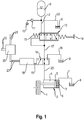
- FIG. 1 1 denotes a parking and / or emergency braking device of a tractor, which in the present case is designed as a multi-disc brake.
- This is engaged or disengaged via a spring-loaded brake cylinder 2 serving as a brake application device, engaging via the force of a compression spring 3 and disengaging via a pressure acting in a pressure chamber 4 which hydraulically acts on a brake piston 5.
- a spring chamber 6 of the spring brake cylinder 2 is connected to a tank 8 via a vent 7.
- the corresponding hydraulic pressure medium to be supplied to the pressure chamber 4 is made available for brake actuation via a pressure accumulator 9, which is filled from a hydraulic system 10 of the tractor, for example the working hydraulics, via a check valve 11.
- a pressure line 12 leads from the pressure accumulator to a valve unit that can also be operated manually in the above explanations designated 3/3-way valve 13, which can be actuated by means of a hand lever or foot pedal 14 against the force of a return spring 15 in three switching positions.
- the 3/3-way valve 13 is followed by a 3/2-way valve 16 serving as a brake actuation valve, the 3/3-way valve 13 and the 3/2-way valve 16 being connected to one another via a working line 17.
- the 3/2-way valve 16 serving as a brake actuation valve can be actuated via an actuating device 18 which, according to the present invention, is intended to ensure that a control slide, not shown in detail, of the 3/2-way valve 16 should be inherently stable in its switching positions.
- the adjusting device 18 adjusts the 3/2-way valve 16 via a linkage 19 optionally in one of its two switching positions.
- the actuating device 18 is connected to an electronic control device 20, which in turn is integrated in a CAN bus 21, whereby various data of the tractor, such as the operating state of the reciprocating internal combustion engine, operating state of the tractor transmission, state of the parking brake, occupancy of the Cabin by the driver, errors in the on-board network, etc.
- the control device 20 has a power supply 22.
- Control lines 23 lead from the control device 20 to the actuating device 18, via which the latter is actuated.
- the 3/3-way valve 13 has a first switching position in which it is currently located and in which the working line 17 is connected to the tank 8 via a return line 24, that is, is depressurized, while the pressure line 12 is blocked. Since the 3/2-way valve 16 is in its flow position, the pressure medium can flow out of the pressure chamber 4 into the tank 8, so that the parking and / or emergency brake device 1 is engaged, i.e. the tractor is in the braked state. In addition, the 3/3-way valve 13 can be adjusted into a blocking position or into a flow position by means of the hand lever or foot pedal 14.
- the 3/2-way valve 16 has in addition to its in Figure 1 set flow position in which it connects the working line 17 to a brake line 25, a drain position in which the brake line 25 is connected to a return line 26.
- FIG. 2 a first embodiment of an actuator according to the invention 18a is shown, in which an electric motor 27 drives a high-ratio gear 29 with a small diameter drive wheel 30 via an output shaft 28, this being in engagement with a large diameter output wheel 31.
- the drive wheel 31 is connected non-rotatably to an output shaft 32, which also receives a drive pinion 33 in a non-rotatable manner. This meshes with a rack 34 of a rack drive 35, which in turn is connected to the linkage 19.
- This rack and pinion drive 35 and the high-ratio gear 29 ensure inherent stability of the entire actuating device 18a.
- an electric motor 36 drives a friction gear 39 designed as a high-ratio gear 38 by means of its output shaft 37.
- a drive wheel 40 with a small diameter is guided within the actuating device in such a way that it causes a longitudinal displacement of the linkage 19 when it rolls on a driven wheel 41 with a large diameter.
- all drive elements are shown in one plane to clarify the function.
- FIG. 3 shows the Figure 3 an exemplary embodiment of an actuating device 18c in which an electric motor 42 is connected via an output shaft 43 which is at least partially designed as a hollow shaft and which is designed as a nut 44 of a roller screw drive 45 at its end facing away from the electric motor 42.
- a plurality of circumferentially distributed thread rollers 47 are guided in the nut 44 via a planet carrier 46. Both the thread rollers 47 and the nut 44 as well as a spindle 48 each have a fine thread 44a, 47a and 48a with an identical thread pitch.
- the thread 47a of the thread rollers 47 which are rotatably guided in the planet carrier 46, is in engagement with the thread 48a of the spindle 48 on the inside and with the thread 44a of the nut 44 on the outside, based on the roller screw drive 45. Besides, they are Threaded rollers 47 are provided at one end with teeth 49 which mesh with a ring gear 50 which is non-rotatably connected to the nut 44, so that they execute a synchronous movement with respect to one another and with respect to the nut 44 and the spindle 48.
- the linear adjusting movement of the spindle 48 is transmitted to the 3/3-way valve 16 via the linkage 19. This creates a bistable actuator for the 3/3-way valve 16.
Landscapes
- Engineering & Computer Science (AREA)
- Transportation (AREA)
- Mechanical Engineering (AREA)
- Braking Systems And Boosters (AREA)
Description
- Die Erfindung betrifft eine Steuereinrichtung für eine hydraulisch betätigte, mit einem Federspeicherbremszylinder als Bremszuspanneinrichtung versehene Feststell- und/oder Notbremseinrichtung, vorzugsweise eines land- oder bauwirtschaftlich nutzbaren Traktors oder Systemfahrzeuges, wobei die Steuereinrichtung zur Steuerung des Druckes in einem Druckraum des Federspeicherbremszylinders vorgesehen und zwischen diesem und einer Druckquelle angeordnet ist, und wobei die Steuereinrichtung ein als Wegeventil ausgebildetes, in zwei unterschiedliche Schaltstellungen aktuierbares Bremsbetätigungsventil aufweist, das über eine elektronische Steuereinrichtung betätigt wird.
- Weiterhin betrifft die Erfindung auch ein Steuersystem einer hydraulisch betätigten Feststell- und/oder Notbremseinrichtung eines land- oder bauwirtschaftlich nutzbaren Fahrzeugs, wobei die Feststell- und/oder Notbremseinrichtung einen Federspeicherbremszylinder mit einem mit Druckmittel beaufschlagbaren Druckraum aufweist, der über ein in zwei Schaltstellungen aktuierbares, über eine elektronische Steuereinheit steuerbares Bremsbetätigungsventil und eine als 3/3-Wegeventil ausgebildete, manuell betätigbare Ventileinheit mit einer als Druckspeicher ausgeführten Druckquelle verbindbar ist, wobei die Ventileinheit eine Durchflussstellung, eine Sperrstellung und eine Ablaufstellung aufweist.
- Feststellbremsen, die über eine automatische Betätigung verfügen und dabei elektronisch angesteuert werden, kommen zunehmend zur Komfortverbesserung an land- oder bauwirtschaftlich nutzbaren Traktoren zum Einsatz. Dabei ist von großer Bedeutung, dass die Bremsbetätigung nicht nur der Aufmerksamkeit des Fahrers überlassen wird, sondern abhängig von Situationen und Betriebszuständen des Traktors generell aktiviert wird. Von einem sich selbstständig in Bewegung setzenden Traktor gehen erhebliche Unfallgefahren aus, insbesondere dann, wenn der Fahrer im Heck- oder Frontbereich des Traktors an diesen Anbaugeräte an- oder abkuppelt sowie an diesen Anbaugeräten oder an den Kuppeleinrichtungen des Traktors Einstellungen vornimmt. Eine elektronisch ansteuerbare Feststellbremse ist außerdem von großer Bedeutung, wenn moderne Traktoren im Rahmen einer Leistungsverzweigung des Getriebes mit einem als CVT-Getriebe (Continuously Variable Transmission) versehen sind, so dass sich der Traktor im aktiven Stillstand bei nicht angetriebener Getriebeeingangswelle, also abgestellter Hubkolbenbrennkraftmaschine, in Bewegung setzen kann. Das kann beispielsweise auch dann der Fall sein, wenn die Hubkolbenbrennkraftmaschine aufgrund eines Kraftstoffmangels zum Stillstand kommt.
- Es ist grundsätzlich wichtig, dass beim Verlassen der Kabine des Traktors durch den Fahrer stets die Feststellbremse betätigt wird, was allerdings häufig nicht der Fall ist. Im Rahmen der Automatisierung von Traktoren ist eine elektronisch ansteuerbare Feststellbremse zwingend notwendig, wobei sichergestellt sein muss, dass der Traktor im Gelände und auf der Straße ohne zusätzliche Betätigung einer entsprechenden Steuervorrichtung sicher abgestellt wird. Ferner ist von Bedeutung, dass die Bremsbetätigung nicht nur auf die Feststellbremse des Traktors sondern auch auf die eines mit diesem verbundenen Anhängers wirkt. Außerdem sollte die Feststellbremse generell beim Abstellen der Hubkolbenbrennkraftmaschine aktiviert sein. Eine elektronisch ansteuerbare Verstellbremse muss hohe Anforderungen an die funktionale Sicherheit erfüllen, damit das Fahrzeug zum einen, wie dargelegt, sicher abgestellt werden kann, aber zum anderen auch die Feststellbremse nicht unbeabsichtigt während der Fahrt aktiviert wird, was zu unkontrollierbaren Fahrzuständen führen kann.
- Außerdem genügen die bekannten Konzepte für elektrohydraulische betätigbare Feststellbremsen, wie nachfolgend dargelegt, nicht mehr den heute erforderlichen Standards für die Entwicklung elektronischer Systeme in landwirtschaftlichen Fahrzeugen. Ein einfacher Fehler in der elektrohydraulischen Betätigung, bei dem zum Beispiel ein Bruch im Kabel eines Fahrzeug Kabelbaums auftritt, ist aufgrund des hohen Anteils an Straßenfahrten des Traktors, die dieser mit seiner hohen Gesamtmasse, zumeist mit Anhängern sowie einer hohen Geschwindigkeit durchführt, nicht mehr akzeptabel. Die Feststellbremse muss außerdem eine sogenannte hill-holder-Funktion erfüllen, bei der beim Anfahrvorgang selbsttätig die Feststellbremse gelöst wird, ohne dass der Traktor samt Anhänger oder Anbaugerät zurückrollt. Grundsätzlich ist es von Bedeutung, dass die zumeist mit einem Federspeicherbremszylinder versehene Bremszuspanneinrichtung auch als Notbremseinrichtung verwendet werden kann, wenn die normale Betriebsbremse ausfällt oder deren Bremsmoment nicht ausreichend ist.
- Eine Steuereinrichtung für eine hydraulisch betätigte, mit einem Federspeicherbremszylinder als Bremszuspanneinrichtung versehene Feststell- und/oder Notbremseinrichtung, vorzugsweise eines land- oder bauwirtschaftlich nutzbaren Traktors oder Systemfahrzeuges der im Oberbegriff der Patentansprüche 1 und 13 angegebenen Gattung ist aus der
DE 10 2008 030 511 B4 bekannt. Diese Bremsanlage weist eine Lamellenbremse auf, die über ein in einem Federspeicherbremszylinder angeordnetes Federelement eingerückt wird, um ein Bremsmoment zu erzeugen. Dieses Bremsmoment kann dadurch aufgehoben werden, dass in einem Druckraum des Federspeicherbremszylinders ein entgegen der Kraft des Federelements wirkender Druck aufgebaut wird. Dieser Druckaufbau in dem Druckraum wird ausgehend von einer als Druckspeicher ausgebildeten Druckquelle über eine erste als 3/2-Wegeventil ausgebildete Ventileinheit gesteuert. - Diese als Bremsbetätigungventil dienende erste Ventileinheit wird in beiden Stellrichtungen über eine elektronische Steuereinheit elektromagnetisch betätigt, wobei die Steuereinheit unter anderem mit einem durch den Fahrer manuell verstellbaren Schaltelement verbunden ist. Die erste Ventileinheit ist außerdem mit einer Rastvorrichtung versehen, über die der entsprechende Steuerschieber bei einer plötzlichen Leistungsunterbrechung in der zuletzt geschalteten Schaltstellung gehalten werden soll. Zwischen dieser ersten Ventileinheit und dem Druckspeicher ist eine zweite Ventileinheit angeordnet, die als 3/3-Wegeventil ausgebildet ist. Diese zweite Ventileinheit weist einen über einen Hebel oder ein Pedal gegen die Kraft einer Druckfeder in drei Schaltstellungen betätigbaren Steuerschieber auf. Mittels der zweiten Ventileinheit soll manuell eine dosierte Betätigung der Feststellbremse erfolgen, vorausgesetzt, die erste Ventileinheit befindet sich in ihrer Durchflussstellung.
- Weitere derartige Steuereinrichtungen sind aus den Entgegenhaltungen
WO2009/156833 A2 ,EP1504975 A1 undEP2974926 A1 bekannt. - Es ist Aufgabe der vorliegenden Erfindung, ein Bremsbetätigungsventil derart zu gestalten, dass dessen Steuerschieber ohne Rastmittel, die zusätzlich zu dessen Stelleinrichtung vorzusehen sind, in der zuletzt eingenommenen Schaltstellung gehalten wird.
- Diese Aufgabe wird, ausgehend von dem jeweiligen Oberbegriff der Patentansprüche 1 und 12 durch deren kennzeichnende Merkmale gelöst. Vorteilhafte Ausgestaltungen sind in den vom Patentanspruch 1 abhängigen Patentansprüchen wiedergegeben, welche jeweils für sich genommen oder in Kombination miteinander einen Aspekt der Erfindung darstellen können.
- Danach ist eine Steuereinrichtung für eine hydraulisch betätigte, mit einem Federspeicherbremszylinder als Bremszuspanneinrichtung versehene Feststell- und/oder Notbremseinrichtung, vorzugsweise eines land- oder bauwirtschaftlich nutzbaren Traktors oder Systemfahrzeuges vorgesehen. Die Steuereinrichtung dient zur Steuerung des Druckes in einem Druckraum des Federspeicherbremszylinders, wobei sie zwischen diesem und einer Druckquelle angeordnet ist und ein als Wegeventil ausgebildetes, elektronisch in zwei unterschiedliche Schaltstellungen aktuierbares Bremsbetätigungsventil aufweist. Dabei wird das Bremsbetätigungsventil über eine elektronische Steuereinheit betätigt. Erfindungsgemäß ist eine Stelleinrichtung des Bremsbetätigungsventils derart ausgebildet, dass diese das Bremsbetätigungsventil in zumindest einer seiner Schaltstellungen eigenstabil hält, so dass dessen Steuerschieber ohne eine weitere Bestromung der Stelleinrichtung in einer zuletzt eingestellten Schaltstellung verbleibt.
- Damit wird verhindert, dass äußere Kräfte eine Änderung der vorgegebenen Schaltstellung des Steuerschiebers hervorrufen. Derartige äußere Kräfte können beispielsweise durch Erschütterungen oder Bauteilbewegungen am Traktor, die beim Überfahren von Fahrbahnunebenheiten auftreten, auf die Stelleinrichtung und auch auf eine Rastiereinrichtung übertragen werden. Durch die innerhalb der Stelleinrichtung vorgesehene Hemmung wird mit einer hohen Funktionssicherheit verhindert, dass die äußeren Kräfte Schaltbewegungen des Steuerschiebers auslösen. Die Eigenstabilität kann in einer oder in beiden Schaltstellungen, also auch bistabil wirken.
- Demgegenüber ist die erste Ventileinheit nach der
DE 10 2008 030 511 B4 mit einer in Verlängerung des Steuerschiebers vorgesehenen Rastvorrichtung versehen. Eine derartige formschlüssig wirkende Rastvorrichtung weist keine ausreichende Ausfallsicherheit auf, d.h., es besteht das Risiko, dass trotz der Rastvorrichtung Fehlschaltungen des Bremsbetätigungsventils ausgelöst werden und daraus Unfallrisiken resultieren. - In weiterer Ausgestaltung der Erfindung ist vorgesehen, dass die Stelleinrichtung einen selbsthemmenden Antrieb aufweist. Dabei weist die Stelleinrichtung vorzugsweise einen von der Steuereinrichtung angesteuerten Elektromotor auf, der ein hochübersetztes Getriebe rotatorisch antreibt. Das hochübersetzte Getriebe kann durch entsprechende Räderpaare bzw. als Planetengetriebe oder Wellgetriebe (beispielsweise Harmonic-Drive-Getriebe) ausgebildet sein. Die geringe Ausgangsdrehzahl des Getriebes wird in eine lineare Stellbewegung gewandelt, die auf den Steuerschieber wirkt. Dabei können die Eigenstabilität bzw. Hemmung innerhalb des Getriebes oder bei der Wandlung der rotativen Bewegung in die lineare Stellbewegung erzielt werden.
- Dabei kann weiterhin vorgesehen sein, dass der elektromotorische Antrieb einen als Synchronmotor ausgebildeten Schrittmotor aufweist. Bei einem Schrittmotor, der als Synchronmotor ausgebildet ist, wird der Rotor um einen vorgegebenen Schrittwinkel gedreht. Dies geschieht durch ein gesteuertes elektromagnetisches Feld, das schrittweise rotiert. Die Verwendung eines Schrittmotors weist im vorliegenden Fall die Vorteile auf, dass Schrittmotoren prinzipbedingt von Schritt zu Schritt einen internen Widerstand aufweisen, der überwunden werden muss, damit die Rotorwelle um einen Winkelschritt gedreht zu werden. Damit wird das Haltemoment verbessert. Außerdem kann der Schrittmotor eine Positionsregelung aufweisen, mit der ein Erreichen einer Sollposition durch Ermittlung der Schritte bestimmbar ist, so dass die Schaltstellungen des Steuerschiebers exakt gesteuert werden können.
- Außerdem ist vorgesehen, dass zur Schaffung eines selbsthemmenden Antriebs das Reibmoment an einem Elektromotor der Stelleinrichtung erhöht wird, indem an einer Rotorwelle des Elektromotors eine Reibeinrichtung vorgesehen ist. Diese als Bremse wirkende Reibeinrichtung kann kontinuierlich wirken oder bei einer Bestromung des Elektromotors ausgerückt werden.
- Weiterhin kann der Stellantrieb als Zahnstangenantrieb, dem ein hochübersetztes Getriebe vorgeschaltet ist, ausgebildet sein. Das hochübersetzte Getriebe liefert an seiner Ausgangswelle eine niedrige Drehzahl und ein hohes Drehmoment, die über ein Zahnrad auf eine Zahnstange übertragen werden. Sowohl der Zahnstangentrieb als auch das hochübersetzte Getriebe sorgen für die geforderte Eigenstabilität der Stelleinrichtung. Eventuell ist es für die Selbsthemmung auch ausreichen, nur einen Zahnstangentrieb vorzusehen.
- Alternativ dazu kann der Stellantrieb einen Spindeltrieb aufweisen. Eine Spindelmutter ist in diesem Fall mit der Ausgangswelle des hochübersetzten Getriebes oder mit dem Rotor des Elektromotors verbunden, während die Spindel am Steuerschieber angreift. Bei einem direkten Antrieb des Spindeltriebs über den Elektromotor weisen die Spindelmutter und die Spindel eine geringe Gewindesteigung auf.
- Es besteht aber auch die Möglichkeit, den Spindeltrieb als Rollengewindetrieb auszubilden. Bei einem Rollengewindetrieb sind zwischen einem Außengewinde einer Spindel und einem Innengewinde einer Mutter planetenartig Gewinderollen angeordnet, die in einem Planetenträger geführt sind. Der Planetentrieb sorgt für eine hohe Übersetzung und für die gemäß der Erfindung vorgesehene Eigenstabilität. Im vorliegenden Fall könnte die Mutter über eine Hohlwelle mit dem Elektromotor verbunden sein, während die Spindel am Steuerschieber angreift. Die Kraftübertragung erfolgt über die Gewindeflanken der Gewinderollen. Ein Rollengewindetrieb weist eine hohe axiale Steifigkeit auf.
- Schließlich soll bei einem Steuersystem einer hydraulisch betätigten Feststell- und/oder Notbremseinrichtung eines land- oder bauwirtschaftlich nutzbaren Fahrzeugs die Feststell- und/oder Notbremseinrichtung einen Federspeicherbremszylinder mit einem mit Druckmittel beaufschlagbaren Druckraum aufweisen. Der Druckraum ist über ein in zwei Schaltstellungen aktuierbares, über eine elektronische Steuereinheit steuerbares Bremsbetätigungsventil und eine als 3/3-Wegeventil ausgebildete, manuell betätigbare Ventileinheit mit einer als Druckspeicher ausgeführten Druckquelle verbindbar. Dabei weist die Ventileinheit eine Durchflussstellung, eine Sperrstellung und eine Ablaufstellung auf. Erfindungsgemäß soll die im Steuersystem verwendete Steuereinrichtung nach einem der vorstehend erläuterten Patentansprüche ausgebildet.
- Die Erfindung ist nicht auf die angegebene Kombination der Merkmale der unabhängigen Patentansprüche 1 und 13 mit den von diesen abhängigen Patentansprüchen beschränkt. Es ergeben sich darüber hinaus Möglichkeiten, einzelne Merkmale, soweit sie aus den Patentansprüchen, den Vorteilsangaben zu den Patentansprüchen, der nachfolgenden Beschreibung des Ausführungsbeispiels oder zumindest aus den Zeichnungen hervorgehen, miteinander zu kombinieren. Die Bezugnahme der Patentansprüche auf die Zeichnung durch entsprechende Verwendung vom Bezugszeichen soll den Schutzumfang der Patentansprüche nicht beschränken.
- Zur weiteren Erläuterung der Erfindung wird auf die Zeichnung verwiesen, in der Ausführungsbeispiele dieser vereinfacht dargestellt sind. Es zeigen:
- Figur 1
- eine schematische Ansicht eines Steuersystems einer hydraulisch betätigten Feststell- und/oder Notbremseinrichtung eines land- oder bauwirtschaftlich nutzbaren Fahrzeugs, die über einen Federspeicherbremszylinder betätigbar ist, wobei ein zur Steuerung des Federspeicherbremszylinders vorgesehenes Bremsbetätigungsventil mittels einer erfindungsgemäß ausgebildeten Stelleinrichtung aktuiert wird,
- Figur 2
- eine erste Ausführungsform der nach
Figur 1 vorgesehenen Stelleinrichtung, bei der diese einen Zahnstangenantrieb aufweist, - Figur 3
- eine zweite Ausführungsform der nach
Figur 1 vorgesehenen Stelleinrichtung, bei der diese ein Reibradgetriebe aufweist und - Figur 4
- eine dritte Ausführungsform der nach
Figur 1 vorgesehenen Stelleinrichtung, bei der diese einen Rollengewindetrieb aufweist. - In der
Figur 1 ist mit 1 eine Feststell- und/oder Notbremseinrichtung eines Traktors bezeichnet, die im vorliegenden Fall als Lamellenbremse ausgebildet ist. Diese wird über einen als Bremszuspanneinrichtung dienenden Federspeicherbremszylinder 2 ein- oder ausgerückt, wobei ein Einrücken über die Kraft einer Druckfeder 3 und ein Ausrücken über einen in einem Druckraum 4 wirkenden Druck, der einen Bremskolben 5 hydraulisch beaufschlagt, bewirkt werden. Ein Federraum 6 des Federspeicherbremszylinders 2 ist über eine Entlüftung 7 mit einem Tank 8 verbunden. - Das entsprechende dem Druckraum 4 zuzuführende hydraulische Druckmittel wird dabei für eine Bremsbetätigung über einen Druckspeicher 9, der aus einem Hydrauliksystem 10 des Traktors, beispielsweise der Arbeitshydraulik, über ein Rückschlagventil 11 befüllt wird, zur Verfügung gestellt. Von dem Druckspeicher führt eine Druckleitung 12 zu einem in den vorstehenden Erläuterungen auch als manuell betätigbare Ventileinheit bezeichnetes 3/3-Wegeventil 13, das mittels eines Handhebels oder Fußpedals 14 entgegen der Kraft einer Rückstellfeder 15 in drei Schaltstellungen betätigbar ist.
- Dem 3/3-Wegeventil 13 ist ein als Bremsbetätigungsventil dienendes 3/2-Wegeventil 16 nachgeschaltet, wobei das 3/3-Wegeventil 13 und dass 3/2-Wegeventil 16 über eine Arbeitsleitung 17 miteinander verbunden sind. Dabei ist das als Bremsbetätigungsventil dienende 3/2-Wegeventil 16 über eine Stelleinrichtung 18 betätigbar, die gemäß der vorliegenden Erfindung bewirken soll, dass ein im Einzelnen nicht dargestellter Steuerschieber des 3/2-Wegeventil 16 in seinen Schaltstellungen eigenstabil sein soll. Die Stelleinrichtung 18 verstellt das 3/2-Wegeventil 16 über ein Gestänge 19 wahlweise in eine seiner beiden Schaltstellungen.
- Die Stelleinrichtung 18 ist mit einer elektronischen Steuereinrichtung 20 verbunden, die ihrerseits in einen CAN-Bus 21 integriert ist, wobei an die Steuereinrichtung 18 unterschiedliche Daten des Traktors, wie z.B. über den Betriebszustand der Hubkolbenbrennkraftmaschine, Betriebszustand des Traktorgetriebes, Zustand der Feststellbremse, Besetzung der Kabine durch den Fahrer, Fehler im Bordnetz usw. übermittelt werden. Die Steuereinrichtung 20 weist eine Stromversorgung 22 auf. Von der Steuereinrichtung 20 führen Steuerleitungen 23 zur Stelleinrichtung 18, über die diese betätigt wird.
- Wie aus der
Figur 1 hervorgeht, weist das 3/3-Wegeventil 13 eine erste Schaltstellung auf, in der es sich aktuell befindet und in der die Arbeitsleitung 17 über eine Rücklaufleitung 24 mit dem Tank 8 verbunden, also drucklos ist, während die Druckleitung 12 gesperrt ist. Da sich das 3/2-Wegeventil 16 in seiner Durchflussstellung befindet, kann das Druckmittel aus dem Druckraum 4 in den Tank 8 ausströmen, so dass die Feststell- und/oder Notbremseinrichtung 1 eingerückt wird, der Traktor sich also im gebremsten Zustand befindet. Darüber hinaus kann das 3/3-Wegeventil 13 mittels des Handhebels oder Fußpedals 14 in eine Sperrstellung oder in eine Durchflussstellung verstellt werden. Das 3/2-Wegeventil 16 weist neben seiner inFigur 1 eingestellten Durchflussstellung, in der es die Arbeitsleitung 17 mit einer Bremsleitung 25 verbindet, eine Ablaufstellung ein, in der die Bremsleitung 25 mit einer Rücklaufleitung 26 verbunden ist. - In der
Figur 2 ist ein erstes Ausführungsbeispiel einer erfindungsgemäßen Stelleinrichtung 18 a dargestellt, bei der ein Elektromotor 27 über eine Ausgangswelle 28 ein hochübersetztes Getriebe 29 mit einem Antriebsrad 30 kleinen Durchmessers antreibt, wobei dieses mit einem Abtriebsrad 31 großen Durchmesser im Eingriff ist. Das Antriebsrad 31 ist drehfest mit einer Abtriebswelle 32 verbunden, welches ebenfalls drehfest ein Antriebsritzel 33 aufnimmt. Dieses kämmt mit einer Zahnstange 34 eines Zahnstangenantriebs 35, die ihrerseits mit dem Gestänge 19 verbunden ist. Dieser Zahnstangenantrieb 35 und das hochübersetzte Getriebe 29 sorgen für eine Eigenstabilität der gesamten Stelleinrichtung 18a. Zur Darstellung der Übertragung des Antriebsdrehmoments vom Elektromotor 27 auf das Antriebsritzel 33 sind alle Antriebselemente zur Verdeutlichung der Funktion in einer Ebene dargestellt. Bei der Realisierung des Antriebs ergeben sich natürlich andere Wellenverläufe und Anordnungen der Räder. - Gemäß der
Figur 3 , die ein zweites Ausführungsbeispiel einer erfindungsgemäßen Stelleinrichtung 18 b dargestellt, treibt ein Elektromotor 36 mittels seiner Ausgangswelle 37 ein als hochübersetztes Getriebe 38 ausgebildetes Reibradgetriebe 39 an. Ein im Durchmesser kleines Antriebsrad 40 ist derart innerhalb der Stelleinrichtung geführt, dass es beim Abrollen an einem im Durchmesser großes Abtriebsrad 41 eine Längsverschiebung des Gestänges 19 bewirkt. Auch in diesem Fall sind zur Darstellung der Übertragung des Antriebsdrehmoments vom Elektromotor 27 auf das Antriebsritzel 33 alle Antriebselemente zur Verdeutlichung der Funktion in einer Ebene dargestellt. Wie bei derFigur 2 ergeben sich zur Realisierung des Antriebs andere Wellenverläufe und Anordnungen der Räder. - Schließlich zeigt die
Figur 3 ein Ausführungsbeispiel einer Stelleinrichtung 18c, bei der ein Elektromotor 42 über eine zumindest teilweise als Hohlwelle ausgebildete Ausgangswelle 43 an, die an ihrem vom Elektromotor 42 abgewandten Ende als Mutter 44 eines Rollengewindetriebs 45 ausgebildet ist. Dabei sind in der Mutter 44 über einen Planetenträger 46 mehrere umfangsverteilte Gewinderollen 47 geführt. Sowohl die Gewinderollen 47 als auch die Mutter 44 sowie eine Spindel 48 weisen jeweils ein Feingewinde 44a, 47a und 48a mit identischer Gewindesteigung auf. - Das Gewinde 47a der Gewinderollen 47, die drehbar im Planetenträger 46 geführt sind, steht, bezogen auf den Rollengewindetrieb 45, innen mit dem Gewinde 48a der Spindel 48 und außen mit dem Gewinde 44a der Mutter 44 im Eingriff. Außerdem sind die Gewinderollen 47 an einem Ende mit Verzahnungen 49 versehen die in ein drehfest mit der Mutter 44 verbundenes Hohlrad 50 kämmen, wodurch diese zueinander sowie gegenüber der Mutter 44 und der Spindel 48 eine synchrone Bewegung ausführen. Die lineare Stellbewegung der Spindel 48 wird über das Gestänge 19 auf das 3/3-Wegeventil 16 übertragen. Dadurch wird ein bistabiler Stellantrieb für das 3/3-Wegeventil 16 geschaffen.
-
- 1
- Feststell- und/oder Notbremseinrichtung
- 2
- Federspeicherbremszylinder
- 3
- Druckfeder
- 4
- Druckraum
- 5
- Bremskolben
- 6
- Federraum
- 7
- Entlüftung
- 8
- Tank
- 9
- Druckspeicher
- 10
- Hydrauliksystem des Traktors
- 11
- Rückschlagventil
- 12
- Druckleitung
- 13
- 3/3-Wegeventil
- 14
- Handhebel oder Fußpedal
- 15
- Rückstellfeder
- 16
- 3/2-Wegeventil
- 17
- Arbeitsleitung
- 18
- Stelleinrichtung
- 18a
- Stelleinrichtung
- 18b
- Stelleinrichtung
- 18c
- Stelleinrichtung
- 19
- Gestänge
- 20
- elektronische Steuereinrichtung
- 21
- CAN-Bus
- 22
- Stromversorgung
- 23
- Steuerleitungen
- 24
- Rücklaufleitung von 12
- 25
- Bremsleitung
- 26
- Rücklaufleitung von 16
- 27
- Elektromotor
- 28
- Ausgangswelle
- 29
- hochübersetztes Getriebe
- 30
- Antriebsrad kleinen Durchmessers
- 31
- Abtriebsrad großen Durchmesser
- 32
- Abtriebswelle
- 33
- Antriebsritzel
- 34
- Zahnstange
- 35
- Zahnstangenantrieb
- 36
- Elektromotor
- 37
- Ausgangswelle
- 38
- hochübersetztes Getriebe
- 39
- Reibradgetriebe
- 40
- im Durchmesser kleines Antriebsrad
- 41
- im Durchmesser großes Abtriebsrad
- 42
- Elektromotor
- 43
- Ausgangswelle
- 44
- Mutter
- 44a
- Gewinde von 44
- 45
- Rollengewindetrieb
- 46
- Planetenträger
- 47
- Gewinderollen
- 47a
- Gewinde von 47
- 48
- Spindel
- 48a
- Gewinde von 48
- 49
- Verzahnung von 47
- 50
- Hohlrad
Claims (12)
- Steuereinrichtung für eine hydraulisch betätigte, mit einem Federspeicherbremszylinder (2) als Bremszuspanneinrichtung versehene Feststell- und/oder Notbremseinrichtung (1), vorzugsweise eines land- oder bauwirtschaftlich nutzbaren Traktors oder Systemfahrzeuges, wobei die Steuereinrichtung zur Steuerung des Druckes in einem Druckraum (4) des Federspeicherbremszylinders (2) vorgesehen und zwischen diesem und einer Druckquelle (9) angeordnet ist, und wobei die Steuereinrichtung ein als Wegeventil ausgebildetes, elektronisch in zwei unterschiedliche Schaltstellungen aktuierbares Bremsbetätigungsventil (16) aufweist, das über eine elektronische Steuereinheit (20) betätigt wird, dadurch gekennzeichnet, dass eine Stelleinrichtung (18, 18a, 19b, 18c) des Bremsbetätigungsventils (16) derart ausgebildet ist, dass diese das Bremsbetätigungsventil (16) in zumindest einer seiner Schaltstellungen eigenstabil hält, so dass dessen Steuerschieber ohne eine weitere Bestromung der Stelleinrichtung (18, 18a, 19b, 18c) in einer zuletzt eingestellten Schaltstellung verbleibt, und die Stelleinrichtung (18, 18a, 19b, 18c) einen selbsthemmenden Antrieb (29, 35, 39, 45) aufweist.
- Steuereinrichtung nach Patentanspruch 1, dadurch gekennzeichnet, dass das Bremsbetätigungsventil (16) als bistabiles Wegeventil ausgeführt ist, dessen Steuerschieber ohne eine Bestromung seiner Stelleinrichtung (18, 18a, 19b, 18c) in jeder seiner beiden zuletzt eingestellten Schaltstellungen verbleibt.
- Steuereinrichtung nach Patentanspruch 1, dadurch gekennzeichnet, dass die Stelleinrichtung (18, 18a, 19b, 18c) einen elektromotorischen Antrieb (27, 36, 42) und einen die rotatorische Antriebsbewegung in eine lineare Stellbewegung wandelnden Stellantrieb (35, 39, 45) aufweist.
- Steuereinrichtung nach Patentanspruch 3, dadurch gekennzeichnet, dass der elektromotorische Antrieb (27, 36, 42) einen als Synchronmotor ausgebildeten Schrittmotor aufweist.
- Steuereinrichtung nach Patentanspruch 4, dadurch gekennzeichnet, dass der Schrittmotor eine Positionsregelung aufweist, mit der ein Erreichen einer Sollposition durch Ermittlung der Schritte bestimmbar ist.
- Steuereinrichtung nach Patentanspruch 1, dadurch gekennzeichnet, dass zur Schaffung eines selbsthemmenden Antriebs das Reibmoments an einem Elektromotor (27, 36, 42) der Stelleinrichtung (18, 18a, 19b, 18c) erhöht wird, indem an einer Rotorwelle des Elektromotors eine Reibeinrichtung vorgesehen ist.
- Steuereinrichtung nach Patentanspruch 3, dadurch gekennzeichnet, dass der Stellantrieb als Zahnstangenantrieb (35), dem ein hochübersetztes Getriebe (29) vorgeschaltet ist, ausgebildet ist.
- Steuereinrichtung nach Patentanspruch 3, dadurch gekennzeichnet, dass der Stellantrieb als Spindeltrieb (45) ausgebildet ist.
- Steuereinrichtung nach Patentanspruch 1, dadurch gekennzeichnet, dass der Stellantrieb als hochübersetztes Reibradgetriebe (39) ausgebildet ist.
- Steuereinrichtung nach Patentanspruch 8, dadurch gekennzeichnet, dass der Spindeltrieb als Rollengewindetrieb (45) ausgebildet ist.
- Steuereinrichtung nach Patentanspruch 1, dadurch gekennzeichnet, dass das Bremsbetätigungsventil (16) als 3/2-Wegeventil ausgebildet ist, das in einer ersten Schaltstellung die Druckquelle (9) mit dem Druckraum (4) und in einer zweiten Schaltstellung den Druckraum (4) mit einem Rücklauf (26) verbindet.
- Steuersystem einer hydraulisch betätigten Feststell- und/oder Notbremseinrichtung (1) eines land- oder bauwirtschaftlich nutzbaren Fahrzeugs, wobei die Feststell- und/oder Notbremseinrichtung (1) einen Federspeicherbremszylinder (2) mit einem mit Druckmittel beaufschlagbaren Druckraum (4) aufweist, der über ein in zwei Schaltstellungen aktuierbares, über eine elektronische Steuereinrichtung (20) steuerbares Bremsbetätigungsventil (16) und eine als 3/3-Wegeventil ausgebildete, manuell betätigbare Ventileinheit (13) mit einer als Druckspeicher (9) ausgeführten Druckquelle verbindbar ist, wobei die Ventileinheit (13) eine Durchflussstellung, eine Sperrstellung und eine Ablaufstellung aufweist, gekennzeichnet durch die Ausbildung der Steuereinrichtung (16) nach einem der Patentansprüche 1 - 11.
Applications Claiming Priority (1)
| Application Number | Priority Date | Filing Date | Title |
|---|---|---|---|
| DE102016118312.1A DE102016118312A1 (de) | 2016-09-28 | 2016-09-28 | Steuereinrichtung und Steuerystem einer hydraulisch betätigten Feststell- und/oder Notbremseinrichtung eines land- oder bauwirtschaftlich nutzbaren Fahrzeugs |
Publications (2)
| Publication Number | Publication Date |
|---|---|
| EP3300976A1 EP3300976A1 (de) | 2018-04-04 |
| EP3300976B1 true EP3300976B1 (de) | 2021-06-16 |
Family
ID=59677009
Family Applications (1)
| Application Number | Title | Priority Date | Filing Date |
|---|---|---|---|
| EP17185553.9A Active EP3300976B1 (de) | 2016-09-28 | 2017-08-09 | Steuereinrichtung und steuersystem einer hydraulisch betätigten feststell- und/oder notbremseinrichtung eines land- oder bauwirtschaftlich nutzbaren fahrzeugs |
Country Status (2)
| Country | Link |
|---|---|
| EP (1) | EP3300976B1 (de) |
| DE (1) | DE102016118312A1 (de) |
Families Citing this family (4)
| Publication number | Priority date | Publication date | Assignee | Title |
|---|---|---|---|---|
| DE102017122772A1 (de) * | 2017-09-29 | 2019-04-04 | Claas Tractor Sas | Steuersystem einer hydraulisch betätigten Bremseinrichtung |
| CN110126800B (zh) * | 2019-05-29 | 2024-07-12 | 安徽合力股份有限公司 | 一种用于叉车电子驻车制动和解锁功能的换向控制阀 |
| AT522561B1 (de) | 2019-07-18 | 2020-12-15 | Siemens Mobility Austria Gmbh | Notbremseinrichtung für ein Schienenfahrzeug |
| SE544528C2 (en) * | 2020-08-26 | 2022-07-05 | Scania Cv Ab | Emergency brake unit for a vehicle, vehicle including such an emergency brake unit and a method of controlling an emergency brake unit |
Family Cites Families (12)
| Publication number | Priority date | Publication date | Assignee | Title |
|---|---|---|---|---|
| US4856622A (en) * | 1987-11-16 | 1989-08-15 | Caterpillar Inc. | Auxiliary actuation mechanism for a brake assembly |
| US5281007A (en) * | 1992-08-21 | 1994-01-25 | Allied-Signal Inc. | Hydraulic actuation system for hydraulically powered parking brakes |
| DE10052260A1 (de) * | 2000-10-19 | 2002-06-13 | Deere & Co | Steuereinrichtung für die Parksperre eines Kraftfahrzeugs |
| DE10336611A1 (de) * | 2003-08-08 | 2005-03-03 | Wabco Gmbh & Co.Ohg | Druckmittelbetriebene Bremsanlage für ein Fahrzeug |
| FR2872877B1 (fr) * | 2004-07-07 | 2006-09-22 | Bosch Gmbh Robert | Dispositif d'actionnement hydraulique de frein de stationnement et procede de commande d'un tel dispositif |
| DE102005042195B4 (de) * | 2005-09-06 | 2016-12-15 | Robert Bosch Gmbh | Feststellbremse für ein Fahrzeug |
| DE102005042194B4 (de) * | 2005-09-06 | 2016-09-15 | Robert Bosch Gmbh | Feststellbremse für ein Fahrzeug |
| DE102008030511B4 (de) | 2008-06-27 | 2013-05-23 | Agco Gmbh | Bremsanlage für ein Fahrzeug |
| DE102011053568B4 (de) * | 2011-09-12 | 2022-03-31 | Linde Material Handling Gmbh | Bremssteuerungssystem einer mobilen Arbeitsmaschine |
| US9421958B2 (en) * | 2014-06-24 | 2016-08-23 | Cnh Industrial America Llc | Braking system for a work vehicle |
| GB201413204D0 (en) * | 2014-07-25 | 2014-09-10 | Agco Int Gmbh | Parking brake |
| DE102014118644A1 (de) * | 2014-12-15 | 2016-06-16 | Linde Material Handling Gmbh | Mobile Arbeitsmaschine mit einer Bremseinrichtung |
-
2016
- 2016-09-28 DE DE102016118312.1A patent/DE102016118312A1/de not_active Withdrawn
-
2017
- 2017-08-09 EP EP17185553.9A patent/EP3300976B1/de active Active
Also Published As
| Publication number | Publication date |
|---|---|
| EP3300976A1 (de) | 2018-04-04 |
| DE102016118312A1 (de) | 2018-03-29 |
Similar Documents
| Publication | Publication Date | Title |
|---|---|---|
| EP3083346B1 (de) | Kraftfahrzeug | |
| EP1708912B1 (de) | Verfahren zum betreiben der bremsausrüstung eines fahrzeugs | |
| EP1743823B1 (de) | Antriebssystem eines Arbeitsfahrzeugs | |
| EP1824698B1 (de) | Verfahren zur steuerung eines bremssystems eines kraftfahrzeuges | |
| EP2130737B1 (de) | Bremsanlage für ein Kraftfahrzeug | |
| DE102017214904B4 (de) | Verfahren zum Einlegen einer Parksperre eines Kraftfahrzeugs, sowie Kraftfahrzeug mit einer Parksperre | |
| DE102017110942A1 (de) | Feststellbremsanlage für ein Kraftfahrzeug und Kraftfahrzeug | |
| EP2420626A1 (de) | Hydraulische Anordnung | |
| EP3300976A1 (de) | Steuereinrichtung und steuersystem einer hydraulisch betätigten feststell- und/oder notbremseinrichtung eines land- oder bauwirtschaftlich nutzbaren fahrzeugs | |
| EP0807561A2 (de) | Rücklaufsperre für Kraftfahrzeuge | |
| DE102018132266A1 (de) | Elektromechanische Bremse, Scheibenbremse und Bremsanlage für ein Kraftfahrzeug | |
| EP2663789A1 (de) | Feststellvorrichtung für ausgleichsgetriebe | |
| EP2539204A1 (de) | Lenksystem mit hydraulischer lenksäule | |
| EP3461707B1 (de) | Steuersystem einer hydraulisch betätigten bremseinrichtung | |
| EP2123500B1 (de) | Verfahren und Vorrichtung zur Ermittlung der Ein- und Ausschaltbedingung für eine Motorbremse einer Dauerbremsanlage eines Fahrzeuges, insbesondere eines Nutzfahrzeuges | |
| WO2017001084A1 (de) | Lenksystem für ein automatisch fahrendes fahrzeug | |
| WO2008086980A1 (de) | Fahrzeug mit pre-safe-sensorik | |
| DE10236216B4 (de) | Betätigungsmechanismus für eine Feststellbremse | |
| DE102008060498B4 (de) | Feststellbremssystem | |
| DE10135862A1 (de) | Fahrzeuglenkung | |
| DE102015216295B3 (de) | Berganfahrhilfe | |
| DE102005001838B4 (de) | Verfahren zur Komfortverbesserung beim Auslegen der Parksperre eines Kraftfahrzeugs | |
| EP4476121A1 (de) | Hilfslenkeinrichtung für eine hydrostatische fahrzeuglenkung | |
| EP1526026B1 (de) | Berghaltevorrichtung in einem Kraftfahrzeug und Verfahren zur Steuerung der Berghaltevorrichtung | |
| EP1902891B1 (de) | Antriebsvorrichtung für Tandemachsen und Verfahren zum Antrieb von Tandemachsen |
Legal Events
| Date | Code | Title | Description |
|---|---|---|---|
| PUAI | Public reference made under article 153(3) epc to a published international application that has entered the european phase |
Free format text: ORIGINAL CODE: 0009012 |
|
| STAA | Information on the status of an ep patent application or granted ep patent |
Free format text: STATUS: THE APPLICATION HAS BEEN PUBLISHED |
|
| AK | Designated contracting states |
Kind code of ref document: A1 Designated state(s): AL AT BE BG CH CY CZ DE DK EE ES FI FR GB GR HR HU IE IS IT LI LT LU LV MC MK MT NL NO PL PT RO RS SE SI SK SM TR |
|
| AX | Request for extension of the european patent |
Extension state: BA ME |
|
| STAA | Information on the status of an ep patent application or granted ep patent |
Free format text: STATUS: REQUEST FOR EXAMINATION WAS MADE |
|
| 17P | Request for examination filed |
Effective date: 20181004 |
|
| RBV | Designated contracting states (corrected) |
Designated state(s): AL AT BE BG CH CY CZ DE DK EE ES FI FR GB GR HR HU IE IS IT LI LT LU LV MC MK MT NL NO PL PT RO RS SE SI SK SM TR |
|
| GRAP | Despatch of communication of intention to grant a patent |
Free format text: ORIGINAL CODE: EPIDOSNIGR1 |
|
| STAA | Information on the status of an ep patent application or granted ep patent |
Free format text: STATUS: GRANT OF PATENT IS INTENDED |
|
| INTG | Intention to grant announced |
Effective date: 20210317 |
|
| GRAS | Grant fee paid |
Free format text: ORIGINAL CODE: EPIDOSNIGR3 |
|
| GRAA | (expected) grant |
Free format text: ORIGINAL CODE: 0009210 |
|
| STAA | Information on the status of an ep patent application or granted ep patent |
Free format text: STATUS: THE PATENT HAS BEEN GRANTED |
|
| AK | Designated contracting states |
Kind code of ref document: B1 Designated state(s): AL AT BE BG CH CY CZ DE DK EE ES FI FR GB GR HR HU IE IS IT LI LT LU LV MC MK MT NL NO PL PT RO RS SE SI SK SM TR |
|
| REG | Reference to a national code |
Ref country code: GB Ref legal event code: FG4D Free format text: NOT ENGLISH |
|
| REG | Reference to a national code |
Ref country code: CH Ref legal event code: EP |
|
| REG | Reference to a national code |
Ref country code: DE Ref legal event code: R096 Ref document number: 502017010650 Country of ref document: DE |
|
| REG | Reference to a national code |
Ref country code: AT Ref legal event code: REF Ref document number: 1402097 Country of ref document: AT Kind code of ref document: T Effective date: 20210715 |
|
| REG | Reference to a national code |
Ref country code: IE Ref legal event code: FG4D Free format text: LANGUAGE OF EP DOCUMENT: GERMAN |
|
| REG | Reference to a national code |
Ref country code: LT Ref legal event code: MG9D |
|
| PG25 | Lapsed in a contracting state [announced via postgrant information from national office to epo] |
Ref country code: BG Free format text: LAPSE BECAUSE OF FAILURE TO SUBMIT A TRANSLATION OF THE DESCRIPTION OR TO PAY THE FEE WITHIN THE PRESCRIBED TIME-LIMIT Effective date: 20210916 Ref country code: HR Free format text: LAPSE BECAUSE OF FAILURE TO SUBMIT A TRANSLATION OF THE DESCRIPTION OR TO PAY THE FEE WITHIN THE PRESCRIBED TIME-LIMIT Effective date: 20210616 Ref country code: FI Free format text: LAPSE BECAUSE OF FAILURE TO SUBMIT A TRANSLATION OF THE DESCRIPTION OR TO PAY THE FEE WITHIN THE PRESCRIBED TIME-LIMIT Effective date: 20210616 Ref country code: LT Free format text: LAPSE BECAUSE OF FAILURE TO SUBMIT A TRANSLATION OF THE DESCRIPTION OR TO PAY THE FEE WITHIN THE PRESCRIBED TIME-LIMIT Effective date: 20210616 |
|
| REG | Reference to a national code |
Ref country code: NL Ref legal event code: MP Effective date: 20210616 |
|
| PG25 | Lapsed in a contracting state [announced via postgrant information from national office to epo] |
Ref country code: LV Free format text: LAPSE BECAUSE OF FAILURE TO SUBMIT A TRANSLATION OF THE DESCRIPTION OR TO PAY THE FEE WITHIN THE PRESCRIBED TIME-LIMIT Effective date: 20210616 Ref country code: GR Free format text: LAPSE BECAUSE OF FAILURE TO SUBMIT A TRANSLATION OF THE DESCRIPTION OR TO PAY THE FEE WITHIN THE PRESCRIBED TIME-LIMIT Effective date: 20210917 Ref country code: NO Free format text: LAPSE BECAUSE OF FAILURE TO SUBMIT A TRANSLATION OF THE DESCRIPTION OR TO PAY THE FEE WITHIN THE PRESCRIBED TIME-LIMIT Effective date: 20210916 Ref country code: SE Free format text: LAPSE BECAUSE OF FAILURE TO SUBMIT A TRANSLATION OF THE DESCRIPTION OR TO PAY THE FEE WITHIN THE PRESCRIBED TIME-LIMIT Effective date: 20210616 Ref country code: RS Free format text: LAPSE BECAUSE OF FAILURE TO SUBMIT A TRANSLATION OF THE DESCRIPTION OR TO PAY THE FEE WITHIN THE PRESCRIBED TIME-LIMIT Effective date: 20210616 |
|
| PG25 | Lapsed in a contracting state [announced via postgrant information from national office to epo] |
Ref country code: CZ Free format text: LAPSE BECAUSE OF FAILURE TO SUBMIT A TRANSLATION OF THE DESCRIPTION OR TO PAY THE FEE WITHIN THE PRESCRIBED TIME-LIMIT Effective date: 20210616 Ref country code: EE Free format text: LAPSE BECAUSE OF FAILURE TO SUBMIT A TRANSLATION OF THE DESCRIPTION OR TO PAY THE FEE WITHIN THE PRESCRIBED TIME-LIMIT Effective date: 20210616 Ref country code: RO Free format text: LAPSE BECAUSE OF FAILURE TO SUBMIT A TRANSLATION OF THE DESCRIPTION OR TO PAY THE FEE WITHIN THE PRESCRIBED TIME-LIMIT Effective date: 20210616 Ref country code: PT Free format text: LAPSE BECAUSE OF FAILURE TO SUBMIT A TRANSLATION OF THE DESCRIPTION OR TO PAY THE FEE WITHIN THE PRESCRIBED TIME-LIMIT Effective date: 20211018 Ref country code: NL Free format text: LAPSE BECAUSE OF FAILURE TO SUBMIT A TRANSLATION OF THE DESCRIPTION OR TO PAY THE FEE WITHIN THE PRESCRIBED TIME-LIMIT Effective date: 20210616 Ref country code: ES Free format text: LAPSE BECAUSE OF FAILURE TO SUBMIT A TRANSLATION OF THE DESCRIPTION OR TO PAY THE FEE WITHIN THE PRESCRIBED TIME-LIMIT Effective date: 20210616 Ref country code: SM Free format text: LAPSE BECAUSE OF FAILURE TO SUBMIT A TRANSLATION OF THE DESCRIPTION OR TO PAY THE FEE WITHIN THE PRESCRIBED TIME-LIMIT Effective date: 20210616 Ref country code: SK Free format text: LAPSE BECAUSE OF FAILURE TO SUBMIT A TRANSLATION OF THE DESCRIPTION OR TO PAY THE FEE WITHIN THE PRESCRIBED TIME-LIMIT Effective date: 20210616 |
|
| PG25 | Lapsed in a contracting state [announced via postgrant information from national office to epo] |
Ref country code: PL Free format text: LAPSE BECAUSE OF FAILURE TO SUBMIT A TRANSLATION OF THE DESCRIPTION OR TO PAY THE FEE WITHIN THE PRESCRIBED TIME-LIMIT Effective date: 20210616 |
|
| REG | Reference to a national code |
Ref country code: DE Ref legal event code: R097 Ref document number: 502017010650 Country of ref document: DE |
|
| REG | Reference to a national code |
Ref country code: CH Ref legal event code: PL |
|
| PG25 | Lapsed in a contracting state [announced via postgrant information from national office to epo] |
Ref country code: MC Free format text: LAPSE BECAUSE OF FAILURE TO SUBMIT A TRANSLATION OF THE DESCRIPTION OR TO PAY THE FEE WITHIN THE PRESCRIBED TIME-LIMIT Effective date: 20210616 |
|
| PLBE | No opposition filed within time limit |
Free format text: ORIGINAL CODE: 0009261 |
|
| STAA | Information on the status of an ep patent application or granted ep patent |
Free format text: STATUS: NO OPPOSITION FILED WITHIN TIME LIMIT |
|
| PG25 | Lapsed in a contracting state [announced via postgrant information from national office to epo] |
Ref country code: LI Free format text: LAPSE BECAUSE OF NON-PAYMENT OF DUE FEES Effective date: 20210831 Ref country code: DK Free format text: LAPSE BECAUSE OF FAILURE TO SUBMIT A TRANSLATION OF THE DESCRIPTION OR TO PAY THE FEE WITHIN THE PRESCRIBED TIME-LIMIT Effective date: 20210616 Ref country code: CH Free format text: LAPSE BECAUSE OF NON-PAYMENT OF DUE FEES Effective date: 20210831 |
|
| 26N | No opposition filed |
Effective date: 20220317 |
|
| GBPC | Gb: european patent ceased through non-payment of renewal fee |
Effective date: 20210916 |
|
| PG25 | Lapsed in a contracting state [announced via postgrant information from national office to epo] |
Ref country code: LU Free format text: LAPSE BECAUSE OF NON-PAYMENT OF DUE FEES Effective date: 20210809 Ref country code: AL Free format text: LAPSE BECAUSE OF FAILURE TO SUBMIT A TRANSLATION OF THE DESCRIPTION OR TO PAY THE FEE WITHIN THE PRESCRIBED TIME-LIMIT Effective date: 20210616 |
|
| PG25 | Lapsed in a contracting state [announced via postgrant information from national office to epo] |
Ref country code: IT Free format text: LAPSE BECAUSE OF FAILURE TO SUBMIT A TRANSLATION OF THE DESCRIPTION OR TO PAY THE FEE WITHIN THE PRESCRIBED TIME-LIMIT Effective date: 20210616 Ref country code: IE Free format text: LAPSE BECAUSE OF NON-PAYMENT OF DUE FEES Effective date: 20210809 Ref country code: GB Free format text: LAPSE BECAUSE OF NON-PAYMENT OF DUE FEES Effective date: 20210916 |
|
| PG25 | Lapsed in a contracting state [announced via postgrant information from national office to epo] |
Ref country code: HU Free format text: LAPSE BECAUSE OF FAILURE TO SUBMIT A TRANSLATION OF THE DESCRIPTION OR TO PAY THE FEE WITHIN THE PRESCRIBED TIME-LIMIT; INVALID AB INITIO Effective date: 20170809 |
|
| P01 | Opt-out of the competence of the unified patent court (upc) registered |
Effective date: 20230516 |
|
| PG25 | Lapsed in a contracting state [announced via postgrant information from national office to epo] |
Ref country code: CY Free format text: LAPSE BECAUSE OF FAILURE TO SUBMIT A TRANSLATION OF THE DESCRIPTION OR TO PAY THE FEE WITHIN THE PRESCRIBED TIME-LIMIT Effective date: 20210616 |
|
| PG25 | Lapsed in a contracting state [announced via postgrant information from national office to epo] |
Ref country code: MK Free format text: LAPSE BECAUSE OF FAILURE TO SUBMIT A TRANSLATION OF THE DESCRIPTION OR TO PAY THE FEE WITHIN THE PRESCRIBED TIME-LIMIT Effective date: 20210616 |
|
| PG25 | Lapsed in a contracting state [announced via postgrant information from national office to epo] |
Ref country code: TR Free format text: LAPSE BECAUSE OF FAILURE TO SUBMIT A TRANSLATION OF THE DESCRIPTION OR TO PAY THE FEE WITHIN THE PRESCRIBED TIME-LIMIT Effective date: 20210616 |
|
| PG25 | Lapsed in a contracting state [announced via postgrant information from national office to epo] |
Ref country code: MT Free format text: LAPSE BECAUSE OF FAILURE TO SUBMIT A TRANSLATION OF THE DESCRIPTION OR TO PAY THE FEE WITHIN THE PRESCRIBED TIME-LIMIT Effective date: 20210616 |
|
| PGFP | Annual fee paid to national office [announced via postgrant information from national office to epo] |
Ref country code: DE Payment date: 20250820 Year of fee payment: 9 |
|
| PGFP | Annual fee paid to national office [announced via postgrant information from national office to epo] |
Ref country code: BE Payment date: 20250820 Year of fee payment: 9 |
|
| PGFP | Annual fee paid to national office [announced via postgrant information from national office to epo] |
Ref country code: AT Payment date: 20250821 Year of fee payment: 9 Ref country code: FR Payment date: 20250828 Year of fee payment: 9 |