EP3300992A1 - Système et procédé de stationnement autonome perpendiculaire d'un véhicule - Google Patents
Système et procédé de stationnement autonome perpendiculaire d'un véhicule Download PDFInfo
- Publication number
- EP3300992A1 EP3300992A1 EP17197647.5A EP17197647A EP3300992A1 EP 3300992 A1 EP3300992 A1 EP 3300992A1 EP 17197647 A EP17197647 A EP 17197647A EP 3300992 A1 EP3300992 A1 EP 3300992A1
- Authority
- EP
- European Patent Office
- Prior art keywords
- vehicle
- parking space
- distance
- parking
- parallel
- Prior art date
- Legal status (The legal status is an assumption and is not a legal conclusion. Google has not performed a legal analysis and makes no representation as to the accuracy of the status listed.)
- Withdrawn
Links
Images


Classifications
-
- B—PERFORMING OPERATIONS; TRANSPORTING
- B60—VEHICLES IN GENERAL
- B60W—CONJOINT CONTROL OF VEHICLE SUB-UNITS OF DIFFERENT TYPE OR DIFFERENT FUNCTION; CONTROL SYSTEMS SPECIALLY ADAPTED FOR HYBRID VEHICLES; ROAD VEHICLE DRIVE CONTROL SYSTEMS FOR PURPOSES NOT RELATED TO THE CONTROL OF A PARTICULAR SUB-UNIT
- B60W30/00—Purposes of road vehicle drive control systems not related to the control of a particular sub-unit, e.g. of systems using conjoint control of vehicle sub-units
- B60W30/06—Automatic manoeuvring for parking
-
- B—PERFORMING OPERATIONS; TRANSPORTING
- B62—LAND VEHICLES FOR TRAVELLING OTHERWISE THAN ON RAILS
- B62D—MOTOR VEHICLES; TRAILERS
- B62D15/00—Steering not otherwise provided for
- B62D15/02—Steering position indicators ; Steering position determination; Steering aids
- B62D15/027—Parking aids, e.g. instruction means
- B62D15/0285—Parking performed automatically
-
- G—PHYSICS
- G05—CONTROLLING; REGULATING
- G05D—SYSTEMS FOR CONTROLLING OR REGULATING NON-ELECTRIC VARIABLES
- G05D1/00—Control of position, course, altitude or attitude of land, water, air or space vehicles, e.g. using automatic pilots
- G05D1/02—Control of position or course in two dimensions
- G05D1/021—Control of position or course in two dimensions specially adapted to land vehicles
- G05D1/0212—Control of position or course in two dimensions specially adapted to land vehicles with means for defining a desired trajectory
- G05D1/0225—Control of position or course in two dimensions specially adapted to land vehicles with means for defining a desired trajectory involving docking at a fixed facility, e.g. base station or loading bay
-
- G—PHYSICS
- G06—COMPUTING OR CALCULATING; COUNTING
- G06V—IMAGE OR VIDEO RECOGNITION OR UNDERSTANDING
- G06V20/00—Scenes; Scene-specific elements
- G06V20/50—Context or environment of the image
- G06V20/56—Context or environment of the image exterior to a vehicle by using sensors mounted on the vehicle
- G06V20/58—Recognition of moving objects or obstacles, e.g. vehicles or pedestrians; Recognition of traffic objects, e.g. traffic signs, traffic lights or roads
- G06V20/586—Recognition of moving objects or obstacles, e.g. vehicles or pedestrians; Recognition of traffic objects, e.g. traffic signs, traffic lights or roads of parking space
-
- G—PHYSICS
- G06—COMPUTING OR CALCULATING; COUNTING
- G06V—IMAGE OR VIDEO RECOGNITION OR UNDERSTANDING
- G06V20/00—Scenes; Scene-specific elements
- G06V20/50—Context or environment of the image
- G06V20/56—Context or environment of the image exterior to a vehicle by using sensors mounted on the vehicle
- G06V20/588—Recognition of the road, e.g. of lane markings; Recognition of the vehicle driving pattern in relation to the road
-
- G—PHYSICS
- G08—SIGNALLING
- G08G—TRAFFIC CONTROL SYSTEMS
- G08G1/00—Traffic control systems for road vehicles
- G08G1/14—Traffic control systems for road vehicles indicating individual free spaces in parking areas
-
- B—PERFORMING OPERATIONS; TRANSPORTING
- B60—VEHICLES IN GENERAL
- B60T—VEHICLE BRAKE CONTROL SYSTEMS OR PARTS THEREOF; BRAKE CONTROL SYSTEMS OR PARTS THEREOF, IN GENERAL; ARRANGEMENT OF BRAKING ELEMENTS ON VEHICLES IN GENERAL; PORTABLE DEVICES FOR PREVENTING UNWANTED MOVEMENT OF VEHICLES; VEHICLE MODIFICATIONS TO FACILITATE COOLING OF BRAKES
- B60T2201/00—Particular use of vehicle brake systems; Special systems using also the brakes; Special software modules within the brake system controller
- B60T2201/10—Automatic or semi-automatic parking aid systems
Definitions
- the invention relates to a system and method for the autonomous parking of a vehicle; more specifically, to a system and method for autonomous perpendicular parking of a vehicle.
- Autonomous vehicles are vehicles that have a high degree of automation that can transport passengers or items from one location to another.
- a typical autonomous vehicle uses a variety of sensors such as cameras, sonic sensors, radar, LiDAR, GPS receivers, and vehicle status sensors.
- An onboard controller determines an appropriate path based on a desired destination input by a user of the vehicle and uses the information gathered by the sensors to instruct the drive control system to navigate the vehicle to the desired destination.
- SAE International Standard J3016 " Taxonomy and Definitions for Terms Related to On-Road Motor Vehicle Automated Driving Systems", issued January 2014 , provides six (6) levels of automation, from SAE Level 0, No Automation, to SAE Level 5, Full Automation.
- the operator of the vehicle could request the initiation of a parking routine for the vehicle to autonomously park itself in an open air parking lot.
- the onboard controller would communicate with the GPS receiver to obtain the current location of the vehicle to calculate a proper path into a parking space having a preassigned GPS coordinate within the parking lot.
- the controller would then continue to receive the GPS signals, obtain environmental information from the vehicle sensors, and communicate with a vehicle drive control system to navigate the vehicle into the parking space following the calculated parking path without further assistance from the operator of the vehicle.
- GPS navigation system While the GPS navigation system is capable of providing the general location of the vehicle on a given road, the GPS navigation system does not provide sufficient fidelity to locate the vehicle within the confines of a single vehicle parking space that has not been previously assigned a GPS coordinate. Typical commercial GPS navigation systems are accurate to within 15 meters on the average, and more modern GPS navigation systems with Wide Area Augmentation System (WAAS) are accurate to approximately three (3) meters. With only a 3-meter accuracy, there is a likely potential for the parking vehicle to park outside the parking space delineated by parking line markings. Furthermore, parking lots located in concrete structures may have limited access to GPS signals, thereby rendering the GPS receiver useless for guiding a vehicle into a parking space.
- WAAS Wide Area Augmentation System
- a method of autonomous perpendicular parking of a vehicle includes the steps of positioning the vehicle proximal to a parking space delineated by a pair of parallel line markings; detecting the pair of parallel line markings and the outer distal end of each of the parallel line markings; driving the vehicle into the parking space between the outer distal end of each of the parallel line markings; determining an entry angle ⁇ as the vehicle is driven into the parking space; and applying a steering angle ⁇ , by a controller, such that the entry angle ⁇ approaches zero degrees as the vehicle is driven into the parking space.
- the entry angle ⁇ is defined as the difference in direction between a longitudinal axis of the vehicle extending in a direction toward the parking space and an axis parallel to the line markings extending in a direction toward the parking space.
- the steering angle ⁇ is defined as the difference in direction between a longitudinal axis of the vehicle extending in a direction toward the parking space and an axis extending in the direction of a front wheel of the vehicle.
- the method includes the step of repositioning the vehicle proximal to the parking space if both the outer distal ends of the pair of parallel line markings are not detected.
- the method includes detecting an end boundary line marking intersecting the pair of parallel line markings and adjusting the steering angle ⁇ such that the degree of the entry angle ⁇ is about zero degrees when the vehicle is immediately adjacent the end boundary line marking.
- the method includes reversing the vehicle, by the controller, away from the end boundary line marking if the entry angle ⁇ does not approach zero degrees as the vehicle is driven toward the end boundary line marking, adjusting the steering angle ⁇ , by the controller, such that the entry angle ⁇ approaches zero as the vehicle is reversing, and re-approaching end boundary line marking while adjusting the steering angle ⁇ such that the degree of the entry angle ⁇ approaches zero as the vehicle is driven toward the end boundary line marking.
- the method includes generating a map of the detected parallel line markings delineating the parking space, localizing the vehicle in the map between the parallel line markings, determining the distances the vehicle is apart from each of the parallel line markings, and reversing the vehicle out of parking space if one of the distances is less than a predetermined distance.
- the vehicle sensors include a first sensor mounted on the right side of the vehicle at a distance X from the rear fascia, and further includes the step of determining a distance X' along the immediate adjacent line marking from adjacent the first sensor to the distal end of the adjacent line marking, and determining the vehicle is within the parking space if the distance X' is equal to or greater than X.
- the vehicle sensor further includes a second sensor mounted on the left side of the vehicle at a distance Y from the rear fascia, and further includes the step of determining a distance Y' along the immediate adjacent line marking from adjacent the second sensor to the distal end of the adjacent line marking, and determining the vehicle is within the parking space if the distance X' is equal to or greater than X and the distance Y' is equal to or greater than Y.
- the method includes the steps of projecting a vector V rearward at a predetermined angle ⁇ from the first sensor, projecting a vector V' rearward at a predetermined angle ⁇ ' from the second sensor, and confirming the vehicle is within the parking space if the vector V intersects one of the parallel line markings and the vector V' intersects the other of the parallel line markings.
- the vector V may include a predetermined length such that the vector V intersects one of the parallel line markings when the vehicle is completely within the parking space.
- a method of parking a vehicle in a parking space delineated by two parallel lines includes the steps of detecting the two parallel lines and a distal end of each of the two parallel lines; determining a distance between the two distal ends; comparing the distance between the two distal ends with a predetermined vehicle width; driving the vehicle in a direction toward the parking space between the two distal ends if the predetermined vehicle width across is less than the distance between the two distal ends; determining an entry angle ⁇ as the vehicle is driven into the parking space; and adjusting the direction of the vehicle such that the entry angle ⁇ approaches zero degrees as the vehicle is driven into the parking space.
- the entry angle ⁇ is defined as the difference in direction between a longitudinal axis of the vehicle extending in a direction toward the parking space and the direction of the parallel lines
- the method includes the steps of determining the distance the vehicle is apart from each of the parallel lines and reversing the direction of the vehicle if the vehicle is within a predetermined distance to one of the parallel lines.
- the method includes the steps determining a distance X from a first reference point on the right side of the vehicle to the rear fascia; determining a distance Y from a second reference point on the left side of the vehicle to the rear fascia; determining a distance X' on the parallel line from adjacent the first reference point to the respective distal end; determining a distance Y' on the parallel line from adjacent the second reference point to the respective distal end; and determining the vehicle is within the parking space if the distance X' is equal to or greater than X and the distance Y' is equal to or greater than Y.
- the method includes the steps detecting an end boundary line intersecting the two parallel lines; determining the distance the vehicle is from the end boundary line marking; and stopping the vehicle if the vehicle is at or less than a predetermined distance to the end boundary line marking.
- the method includes the steps of projecting a vector V at a predetermined angle ⁇ from the first reference point; projecting a vector V' at a predetermined angle ⁇ ' from the second reference point; and confirming the vehicle is within the parking space if the vector V intersects one of the parallel lines and vector V' intersects the other of the parallel lines.
- a system for autonomous perpendicular parking of a vehicle includes a plurality of imaging sensors configured to detect line markings on the front, right side, and left side of the vehicle; a plurality of ranging sensors configured to detect the line markings on the front, right, and left side of the vehicle, and objects in a path of the vehicle; and a controller communicatively coupled to the plurality of imaging sensors and the plurality of ranging sensors.
- the controller is configured to initiate a parking routine if at least one of the imaging sensors detect a pair of parallel line markings having respective distal ends.
- the controller is configured adjust the vehicle steering such that an entry angle ⁇ of the vehicle approaches zero degrees as the vehicle is driven into the parking space, wherein the entry angle ⁇ is defined as the difference in direction between a longitudinal axis of the vehicle and the direction of the parallel line markings.
- the controller is further configured to generate a map of the detected parallel line markings delineating a parking space; locate the vehicle in the map; determine the distances the vehicle is apart from each of the parallel line markings; and reverse the vehicle out of the parking space if one of the distances is less than a predetermined distance.
- the system further includes a sensor is mounted on a side of the vehicle at a predetermined distance X from the rear fascia of the vehicle.
- the sensor is configured to detect an exterior distal end of the immediately adjacent line marking.
- the controller is configured to determine a distance X' along the line marking from a point A immediately adjacent the sensor to the distal end of the line and determine the vehicle is within the parking space if the distance X' is equal to or greater than X.
- the controller is further configured to project a vector V at a predetermined angle ⁇ from the first reference point; project a vector V' at a predetermined angle ⁇ ' from the second reference point; and confirm the vehicle is within the parking space if the vector V intersects one of the parallel line markings and vector V' intersects the other of the parallel line markings.
- the controller is further configured to detect an end boundary line marking intersecting the two parallel line markings; determine the distance the vehicle is from the end boundary line marking; and brake the vehicle if the vehicle is at or less than a predetermined distance to the end boundary line marking.
- FIG. 1 shows a block diagram of an autonomous parking system 10 for a vehicle 11.
- the autonomous parking system 10 includes a controller 12 in communication with a plurality of imaging sensors 14, a plurality of ranging sensors 16, a plurality of vehicle state sensors 17, and a vehicle control system 18.
- the autonomous parking system 10 is operable to identify an available parking space, generate a parking lane map, calculate a proper path into the parking space, navigate the vehicle 11 through the calculated parking path into the parking space, and properly position the vehicle 11 within the parking space.
- a passenger type vehicle 11 having the autonomous parking system 10.
- the vehicle 11 may be also that of a truck, sport utility vehicle, van, motor home, or any other type of vehicle without departing from the scope of the present disclosure.
- the vehicle 11 includes a front fascia 20, a rear fascia 22, a right side 24, and a left side 26.
- the vehicle 11 includes a vehicle length (L) extending along a vehicle central longitudinal axis A1 and a vehicle width (W).
- the vehicle 11 also includes a reference point RP on the right side 24 of the vehicle 11.
- the reference point RP may be that of the right side mirror and is located at a predetermined distance X from the right edge 22A of the rear fascia 22.
- the vehicle 11 includes a reference point RP' on the left side 26 of the vehicle 11 that is located at a predetermined distance Y from the left edge 22B of the rear fascia 22.
- the reference points RP, RP' are used as part of a method to properly position the vehicle 11 within a perpendicular type parking space, as will be described in greater detail below.
- the imaging sensors 14 may include electronic cameras configured to capture visual information in the visible light spectrum and/or in a non-visual (e.g. infrared) portion of the light spectrum in the field of view of the respective camera. More specifically, the electronic cameras are configured to capture light waves reflected from lane markings such as parking line markings.
- the imaging sensors 14 may include a front facing camera 14A, a rear facing camera 14B, a right facing camera 14C, and left facing camera 14D. Data input from the individual cameras 14A, 14B, 14C, 14D may be fused to provide a 360° field of view with respect to the vehicle 11.
- the ranging sensors 16 may include any ranging technology, including radar, laser, sonic devices, etc., operable to detect objects proximal to the vehicle 11 and to determine the distances from the objects to the vehicle 11. The direction of the objects from the vehicle 11 may be determined based on the locations of the placement of the ranging sensors 16 on the vehicle 11.
- a front ranging sensors 16A is shown mounted on the front fascia 20, a rear ranging sensor 16B mounted on the rear fascia 22, a right ranging sensor 16C mounted on the right side 24, and a left ranging sensor 16D is mounted on the left side 26 of the vehicle 11.
- a right sensor 19A configured to detect and to determine the distances of lane markings immediate to the right of the vehicle 11 is mounted on the reference point RP.
- a left sensor 19B configured to detect and to determine the distances of lane markings immediate to the left side 26 of the vehicle 11 is mounted on the reference point RP'.
- the sensors 19A, 19B may be that of an imaging sensor 14, a ranging sensor 16, or a combination of imaging/ranging sensor.
- a Light Detection and Ranging (LiDAR) sensor 19 may be used in conjunction with or in lieu of the imaging sensors 14 and/or ranging sensors 16.
- the exemplary vehicle 11 is shown with a LiDAR sensor 19A, 19B mounted on the right side 24 and on the left side 26 of the vehicle 11.
- the controller 12 includes a processor 28 and non-transitory computer readable memory 30.
- the processor 28 and memory 30 are shown as being within the same housing; however, it should be understood by those of ordinary skill in the art that the processor 28 and/or memory 30 may actually include multiple processors or memories that may or may not be stored within the same housing.
- one or more processors may be a commercially available central processing unit (CPU) or an application-specific integrated circuit (ASIC) designed for a specific application.
- the controller 12 may employ analog and/or digital control circuity including ASIC for processing the input data from the imaging sensors 14 and ranging sensors 16. It should be appreciated that the ASIC processor may be built into the circuity of the each of the imaging sensors 14 and ranging sensors 16.
- the non-transitory memory 30 stores a database 32 containing reference road markings as defined by the United States Department of Transportation for conveying messages to roadway users, including reference parking line markings for delineating a parking space 46.
- the database 32 also contains reference images of types of parking space 46 delineated by the parking line markings, such as angled parking, parallel parking, and perpendicular parking spaces.
- the database 32 may also contain reference images of objects that are commonly found in a parking lot or parking structure, such as cones, barriers, and pedestrians.
- the non-transitory memory 30 may store multiple routines 34 for the autonomous operation of the vehicle 11 that are implemented by the processor 28.
- One of the routines 34 includes a method 100 of autonomous perpendicular parking of the vehicle 11.
- the exemplary vehicle 11 includes a plurality of vehicle state sensors 17 such as a speed sensor, steering angle sensor 17A, inertial measure unit (IMU), etc. communicatively coupled with the controller 12 to determine the state of the vehicle 11.
- the controller 12 takes the input data from the imaging sensors 14, ranging sensors 16, and vehicle state sensors 17 for communicating with the vehicle control system 18 for autonomous operation of the vehicle 11.
- the vehicle control system 18 includes any systems that implement the autonomous parking functions which include parking the vehicle 11.
- the vehicle control system 18 may include a braking control system 36, throttle control system 38, transmission control system 40, steering control system 42, etc.
- FIG. 2 shows the exemplary vehicle 11 equipped with the system 10 of FIG. 1 within a general parking lot 45 having a plurality of parking spaces 46.
- the parking lot 45 may have any configuration including that of a covered parking structure or open air parking area without departing from the scope of the present disclosure.
- the exemplary vehicle 11 is shown in three (3) progressing positions I, II, and III as the vehicle 11 maneuvers down an aisle 47 of the parking lot 45 toward an available perpendicular parking space 46.
- the available parking space 46 is delineated by a pair of parallel parking line markings 48, 48' and an end boundary line marking 50 intersecting the pair of parallel parking line markings 48, 48'.
- the line markings 48, 48' and end boundary line 50 are imprinted or painted onto the surface of the parking lot 45.
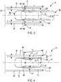
- FIG. 3 shows the vehicle 11 entering into the parking space 46 as the processor 28 fuses the input data from the imaging sensors 14 and ranging sensors 16 to generates a parking lane map localizing the vehicle 11 within the parallel parking line markings 48, 48'.
- the exemplary vehicle 11 is shown in two (2) progressing positions IV and V as the vehicle 11 enters into the available parking space 46.
- Fig. 4 shows the vehicle 11 parked within the parking space 46 undergoing a final check to confirm the vehicle 11 is properly positioned within the parking space 46.
- the vehicle 11 is properly positioned when the vehicle 11 is approximately centered within the pair of parallel parking lines 48, 48' and the rear fascia 22 of the vehicle 11 does not extend past the two end points A, A' into the aisle 47.
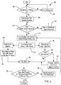
- FIG. 5 shows a flow diagram for a method 100 of autonomously perpendicularly parking a vehicle 11.
- the method 100 begins at step 102, by determining whether the vehicle 11 is presently within the parking lot 45 having parking spaces delineated by parking line markings. If the vehicle 11 is not within the parking lot 45, at step 104, the operator of the vehicle 11 or the autonomous parking system 10 finds a parking lot 45 that has parking spaces delineated by parking line markings.
- the vehicle 11 initiates a sensor point detection algorithm to find an available parking space 46 as the vehicle 11 maneuvers through position I as shown in FIG. 2 .
- the sensor point detection algorithm includes the processor 28 analyzing the images captured by the imaging sensors 14 to detect the parallel parking line markings 48, 48' delineating the parking space 46, compare the parking line markings 48, 48' with reference parking line images in the database 32, and identifies the type of parking space 46 as being a perpendicular type parking space 46.
- the controller 12 analyzes the data input from the imaging and/or ranging sensors 14, 16 directed toward the parking space 46 to confirm that the parking space 46 is not occupied and it is available. Once availability of the parking space 46 is confirmed, the vehicle 11 maneuvers proximal to the distal ends, point A and point A', of the parallel parking line markings 48, 48'.
- the vehicle 11 is approximately at position II as shown in FIG. 2 .
- the processor 28 analyzes the images captured by the imaging sensors 14 to detect the outer distal ends, point A and point A', of the parallel parking line markings 48, 48'. If the outer distal ends, point A and point A', are not detected in the captured images, then at step 108, the vehicle 11 is repositioned until both point A and point A' are captured by the imaging sensors 14 and detected by the processor 28.
- the vehicle 11 is approximately at position III as shown in FIG. 2 .
- the controller 12 initiates pre-alignment and centers the vehicle 11 between the parallel lines 48, 48'.
- the processor 28 analyzes the images to determine the parking space width (w) between point A and point A'. If the width of the parking space (w) is greater than the vehicle width (W) of the vehicle 11, the controller 12 then takes the input data from the imaging sensors 14 and ranging sensors 16 to identify the central axis A2 of the parking space 46 and calculates a proper path to navigate the vehicle 11 into the parking space 46.
- the central axis A2 is the axis that extends into the parking space 46 midway between points A and A' and parallel with the parallel parking line markings 48, 48'.
- the processor 28 fuses the data input from the imaging sensors 14 and ranging sensor 16 to generate a parking lane map of the parking space 46 as the vehicle 11 is maneuvering into the parking space 46.
- the parking space 46 is delineated by the two parallel lines 48, 48' and the end boundary line 50.
- the controller 12 initiates a center vehicle algorithm to center the vehicle 11 between the two parallel lines 48, 48'. Simultaneously, at step 116, the controller 12 initiates a calculate line length algorithm to determine when the vehicle has completely entered the parking space.
- the center vehicle algorithm includes the controller 12 instructing the vehicle control system 18 to apply a steering angle ⁇ , such that the entry angle ⁇ approaches zero degrees as the vehicle 11 is driven into the parking space 46 while aligning the central axis A1 of the vehicle 11 with the central axis A2 of the parking space 46.
- the controller 12 communicates with the vehicle state sensors 17 and vehicle control system 18 to operate the vehicle brake control 36, throttle control 38, transmission control 40, and steering control 42 to autonomously navigate the vehicle 11 into the parking space 46 between the outer distal ends, point A and point A'.
- the vehicle state sensor 17 includes a steering angle sensor 17A that is configured to measure the steering angle of the front wheels 21 relative to the longitudinal axis A1 of the vehicle 11.
- the processor 28 analyzes the images captured by the imaging sensors 14 to determine an entry angle ⁇ as the vehicle 11 is driven into the parking space 46 while aligning the central axis A1 of the vehicle 11 with the central axis A2 of the parking space 46.
- the entry angle ⁇ is defined as the difference in direction between the central longitudinal axis A1 of the vehicle 11 and the central axis A2 of the parking space 46.
- the controller 12 then instructs the vehicle control system 18 to adjust the steering angle ⁇ , such that the entry angle ⁇ approaches zero degrees as the vehicle 11 is driven into the parking space 46, while continuing to align the central longitudinal axis A1 of the vehicle 11 with the central longitudinal axis A2 of the parking space 46.
- the angle ⁇ is defined as the difference in direction between a longitudinal axis of the vehicle A1 extending in a direction toward the parking space 46 and an axis extending in the direction of front wheel of the vehicle A3. It is preferable that the steering angle ⁇ is adjusted such that the degree of the entry angle ⁇ is about zero degrees when the vehicle 11 is completely within the parking space 46.
- the amount of adjustment of the steering angle ⁇ to achieve a 0-degree entry angle ⁇ as the vehicle 11 is driven into the parking space 46 may be obtained from a predefined relationship or lookup table for the specific type of vehicle stored in the database 32.
- the vehicle 11 is reversed while adjusting the steering angle ⁇ such that the entry angle ⁇ approaches zero degrees as the vehicle 11 is reversing.
- the vehicle 11 re-approaches the end boundary line marking 50 while adjusting the steering angle ⁇ such that the degree of the entry angle ⁇ approaches zero as the vehicle 11 is driven toward the end boundary line marking while aligning the central longitudinal axis A1 of the vehicle 11 with the central longitudinal axis A2 of the parking space 46.
- the calculate line length algorithm includes the processor 28 comparing the reference distance X to measured length X' on the parking line marking to the right side 24 of the vehicle 11 and reference length Y to measured length Y' on the parking line marking on the left side 26 of the vehicle 11.
- the LiDAR sensors 19A, 19B are configured to detect parking line markings 48, 48' to the right and left of the vehicle 11 and to determine the distances Z, Z' to the parking line markings 48, 48'.
- the right side LiDAR sensor 19A measures a distance X' along the parking line marking 48 from a point B on the line marking 48 immediately adjacent the LiDAR sensor 19A to the distal end point A.
- the processor 28 compares X' to X and determines the vehicle 11 to be within the parking space 46 if the measured distance X' is greater than reference distance X.
- the vehicle 11 has a reference distance Y, which is measured from the left side LiDAR sensor 19B, or reference point RP', to the left rear edge 22B of rear fascia 22.
- the LiDAR sensor 19B is configured to measure a distance Y' along the parking line marking 48' from a point B' immediately adjacent the LiDAR sensor 19B to the distal end point A'.
- the processor 28 compares Y' to Y and determines the vehicle 11 to be within the parking space 46 if the measured distance Y' is greater than reference distance Y.
- the measured distances X' and Y' relative to the reference distances X and Y may be determined from the generated lane map.
- the controller 12 instructs the vehicle control system 18 to stop the vehicle 11 and place the transmission in park when one of the following first occurs: (i) X' is equal to or greater than X and Y' is equal to or greater than Y, or (ii) when the front of the vehicle 11 is immediate adjacent the end boundary line marking 50.
- the rear fascia 22 of the vehicle 11 may still extend outside the parking space 46.
- a parking space sized for a compact vehicle may not accommodate the entire length of a full size vehicle such as a mini-van. Therefore, at step 126, once it is determined that X is equal to X' and Y is equal to Y', or if when the front of the vehicle 11 is immediately adjacent the end boundary line marking 50, and the steering angle ⁇ and entry angle ⁇ are approximately zero degrees, the controller 12 conducts a final check at step 124 to verify the vehicle 11 is completely within the parking space 46.
- a vector V is projected at a predetermined angle ⁇ from the right side 24 of the vehicle 11, and similarly a vector V' is projected at a predetermined angle ⁇ ' from the left side 26 of the vehicle 11.
- the vehicle 11 is determined to be within the parking space 46 if the vector V intersects the parking line marking immediately to the right side 24 of the vehicle 11 and the vector V' intersects the parking line marking immediately to the left side 26 of the vehicle 11.
- the vector V has a predetermined length V L and angle ⁇ is projected rearward from the reference point RP on the right side 24 of the vehicle 11.
- a vector V' having a predetermined length V L and angle ⁇ ' is projected rearward from the reference point RP' on the left side 26 of the vehicle 11.
- the projections may be a virtual projection on the generated parking lane map, or may be an actual projection on the surface of the parking space 46.
- the vehicle 11 is determined to be within the parking space 46 if the vector V, having an angle ⁇ projected from a reference point RP on the right side 24 of the vehicle 11, intersects the parking line marking 48 and the vector V', having an angle ⁇ ' projected from a reference point RP' on the left side 26 of the vehicle 11, intersects the parking line marking 48'.
- the length V L of the vector V that is required to intersect the adjacent parking line marking 48 on the right side 24, when the vehicle 11 is properly in position within the parking space 46, is calculated by using the Pythagorean Theorem. This is based on the premise that the longitudinal axis A1 of the vehicle 11 is parallel with the longitudinal axis A2 of the parking space 46, which is parallel with the parking line markings 48, 48'. For the purpose of determining the angle ⁇ , it is necessary to first assume that the vehicle 11 is completely within the parking space 46 by extending the parking line markings 48, 48' outward beyond the rear fascia 22 of the vehicle 11.
- a right triangle (RT) is defined by the reference point RP, the right edge 22A of the rear fascia 22, and a point C on the parking line marking 48, or the extension of the parking line marking, immediately adjacent the right edge 22A of the rear fascia 22.
- the base (b) of the right triangle (RT) is the distance X between the right edge 22A of the rear fascia 22 to the reference point RP.
- the height (h) of the right triangle is the distance between point C on the parking line marking 48, or extension of the parking line marking 48, immediate adjacent the right rear edge 22A of the rear fascia 22.
- the height (h) of the right triangle (RT) is the same as the distance Z between the reference point RP and the point B on the parking line 48.
- the vector length V L is the hypotenuse connecting the reference point RP to the parking line marking 48 at point C.
- an angle ⁇ can be calculated to provide the proper length vector V L that would intersect the parking line marking 48 when the vehicle 11 is properly in the parking space 46.
- the angle ⁇ ' is calculated based on the corresponding features on the left side 26 of the vehicle 11. If the vehicle 11, is perfectly centered, then V L should equal V L '. However, the vehicle need not be perfectly centered, but substantially centered such that the vehicle is between the parking line markings 48, 48' with at least 6 inches between the vehicle 11 and the respective parking line markings 48, 48'.
- the vehicle 11 is confirmed to be within the parking space 46 if the vector V intersects the actual parking line marking 48, not the projection of the parking line marking 48, immediately to the right side 24 of the vehicle 11 and the vector V' intersects the actual parking line marking 48' immediately to the left side 26 of the vehicle 11.
- step 130 if both of the projected vectors V, V' do not intersect their respective adjacent parking line markings 48, 48', then the vehicle 11 is reversed out of the parking space 46 and the method 100 returns to step 110 or the parking routine is aborted. If both of the projected vectors V, V' intersect with their respective adjacent parking line markings 48, 48', then the vehicle 11 is properly parked.
Landscapes
- Engineering & Computer Science (AREA)
- General Physics & Mathematics (AREA)
- Physics & Mathematics (AREA)
- Transportation (AREA)
- Mechanical Engineering (AREA)
- Multimedia (AREA)
- Theoretical Computer Science (AREA)
- Combustion & Propulsion (AREA)
- Chemical & Material Sciences (AREA)
- Automation & Control Theory (AREA)
- Aviation & Aerospace Engineering (AREA)
- Radar, Positioning & Navigation (AREA)
- Remote Sensing (AREA)
- Control Of Driving Devices And Active Controlling Of Vehicle (AREA)
Applications Claiming Priority (1)
| Application Number | Priority Date | Filing Date | Title |
|---|---|---|---|
| US15/278,589 US20180086381A1 (en) | 2016-09-28 | 2016-09-28 | System and method for autonomous perpendicular parking of a vehicle |
Publications (1)
| Publication Number | Publication Date |
|---|---|
| EP3300992A1 true EP3300992A1 (fr) | 2018-04-04 |
Family
ID=60186036
Family Applications (1)
| Application Number | Title | Priority Date | Filing Date |
|---|---|---|---|
| EP17197647.5A Withdrawn EP3300992A1 (fr) | 2016-09-28 | 2017-10-20 | Système et procédé de stationnement autonome perpendiculaire d'un véhicule |
Country Status (3)
| Country | Link |
|---|---|
| US (1) | US20180086381A1 (fr) |
| EP (1) | EP3300992A1 (fr) |
| CN (1) | CN107867287A (fr) |
Cited By (1)
| Publication number | Priority date | Publication date | Assignee | Title |
|---|---|---|---|---|
| CN112509364A (zh) * | 2020-11-17 | 2021-03-16 | 北京精英路通科技有限公司 | 车辆停车状态的确定方法、装置、计算机设备及存储介质 |
Families Citing this family (19)
| Publication number | Priority date | Publication date | Assignee | Title |
|---|---|---|---|---|
| US11691619B2 (en) * | 2015-08-12 | 2023-07-04 | Hyundai Motor Company | Automatic parking system and automatic parking method |
| US10392009B2 (en) * | 2015-08-12 | 2019-08-27 | Hyundai Motor Company | Automatic parking system and automatic parking method |
| US10606257B2 (en) * | 2015-11-10 | 2020-03-31 | Hyundai Motor Company | Automatic parking system and automatic parking method |
| US10481609B2 (en) * | 2016-12-09 | 2019-11-19 | Ford Global Technologies, Llc | Parking-lot-navigation system and method |
| JP7095968B2 (ja) | 2017-10-02 | 2022-07-05 | トヨタ自動車株式会社 | 管理装置 |
| DE112019002309B4 (de) * | 2018-06-22 | 2024-11-07 | Hitachi Astemo, Ltd. | Fahrzeugsteuervorrichtung |
| CN109506693B (zh) * | 2018-09-26 | 2024-10-29 | 魔门塔(苏州)科技有限公司 | 一种自动驾驶汽车数据采集用隐藏式支架及其采集方法 |
| KR102703739B1 (ko) * | 2019-02-25 | 2024-09-09 | 현대자동차주식회사 | 차량의 원격 주차 제어 장치 및 그 방법 |
| US11409302B2 (en) * | 2019-03-03 | 2022-08-09 | Wipro Limited | Method for autonomous parking of a vehicle, and an autonomous vehicle thereof |
| JP7296768B2 (ja) * | 2019-04-22 | 2023-06-23 | フォルシアクラリオン・エレクトロニクス株式会社 | 画像処理装置及び画像処理方法 |
| EP3966654B1 (fr) * | 2019-07-31 | 2024-07-31 | Hewlett-Packard Development Company, L.P. | Positionnement de véhicules autonomes |
| EP3809313B1 (fr) * | 2019-10-16 | 2025-01-29 | Ningbo Geely Automobile Research & Development Co., Ltd. | Système de support de dispositif de recherche de stationnement de véhicule, procédé et produit programme informatique pour déterminer si un véhicule se trouve au niveau d'un emplacement de stationnement de référence |
| JP7358017B2 (ja) * | 2019-11-20 | 2023-10-10 | 株式会社ディスコ | 搬送車及び搬送システム |
| JP6975766B2 (ja) * | 2019-12-13 | 2021-12-01 | 本田技研工業株式会社 | 駐車支援装置、駐車支援方法及びプログラム |
| US11427195B1 (en) * | 2020-02-07 | 2022-08-30 | Ambarella International Lp | Automatic collision detection, warning, avoidance and prevention in parked cars |
| US20230031425A1 (en) * | 2021-08-02 | 2023-02-02 | DUS Operating Inc, | Methodology to estimate slot line direction for parking slot detection |
| CN114228703B (zh) * | 2022-01-29 | 2023-11-17 | 中国第一汽车股份有限公司 | 一种自动泊车方法、系统、车辆及存储介质 |
| US20230311854A1 (en) * | 2022-03-29 | 2023-10-05 | Continental Autonomous Mobility US, LLC | Autonomous vehicle garage parking |
| CN118310512A (zh) * | 2024-03-22 | 2024-07-09 | 惠州华阳通用电子有限公司 | 一种定位修正方法 |
Citations (3)
| Publication number | Priority date | Publication date | Assignee | Title |
|---|---|---|---|---|
| EP1674376A2 (fr) * | 2004-12-21 | 2006-06-28 | Aisin Seiki Kabushiki Kaisha | Dispositf d'assistance au parking |
| US20080154464A1 (en) * | 2006-12-26 | 2008-06-26 | Honda Motor Co., Ltd. | Automatic Parking control apparatus for vehicle |
| US20150097956A1 (en) * | 2013-10-04 | 2015-04-09 | Aisin Seiki Kabushiki Kaisha | Parking assistance device |
Family Cites Families (7)
| Publication number | Priority date | Publication date | Assignee | Title |
|---|---|---|---|---|
| JP4020128B2 (ja) * | 2005-04-22 | 2007-12-12 | トヨタ自動車株式会社 | 目標位置設定装置およびそれを備えた駐車支援装置 |
| US7573402B2 (en) * | 2005-08-25 | 2009-08-11 | Herbert William J | Dual laser beam guidance and parking device |
| CN101765527A (zh) * | 2007-07-31 | 2010-06-30 | 株式会社丰田自动织机 | 停车辅助装置、停车辅助装置的车辆侧装置、停车辅助方法及停车辅助程序 |
| JP4433060B2 (ja) * | 2008-02-18 | 2010-03-17 | トヨタ自動車株式会社 | 駐車支援装置 |
| DE102010032462B4 (de) * | 2010-07-28 | 2021-09-16 | Volkswagen Aktiengesellschaft | Verfahren und Vorrichtung zum Einparken eines Kraftfahrzeugs |
| JP6251940B2 (ja) * | 2014-06-30 | 2017-12-27 | 日立オートモティブシステムズ株式会社 | 駐車軌跡算出装置および駐車軌跡算出方法 |
| US9906505B2 (en) * | 2015-05-08 | 2018-02-27 | Nxp B.V. | RSA decryption using multiplicative secret sharing |
-
2016
- 2016-09-28 US US15/278,589 patent/US20180086381A1/en not_active Abandoned
-
2017
- 2017-09-13 CN CN201710822532.7A patent/CN107867287A/zh active Pending
- 2017-10-20 EP EP17197647.5A patent/EP3300992A1/fr not_active Withdrawn
Patent Citations (3)
| Publication number | Priority date | Publication date | Assignee | Title |
|---|---|---|---|---|
| EP1674376A2 (fr) * | 2004-12-21 | 2006-06-28 | Aisin Seiki Kabushiki Kaisha | Dispositf d'assistance au parking |
| US20080154464A1 (en) * | 2006-12-26 | 2008-06-26 | Honda Motor Co., Ltd. | Automatic Parking control apparatus for vehicle |
| US20150097956A1 (en) * | 2013-10-04 | 2015-04-09 | Aisin Seiki Kabushiki Kaisha | Parking assistance device |
Cited By (2)
| Publication number | Priority date | Publication date | Assignee | Title |
|---|---|---|---|---|
| CN112509364A (zh) * | 2020-11-17 | 2021-03-16 | 北京精英路通科技有限公司 | 车辆停车状态的确定方法、装置、计算机设备及存储介质 |
| CN112509364B (zh) * | 2020-11-17 | 2021-11-09 | 北京精英路通科技有限公司 | 车辆停车状态的确定方法、装置、计算机设备及存储介质 |
Also Published As
| Publication number | Publication date |
|---|---|
| US20180086381A1 (en) | 2018-03-29 |
| CN107867287A (zh) | 2018-04-03 |
Similar Documents
| Publication | Publication Date | Title |
|---|---|---|
| EP3300992A1 (fr) | Système et procédé de stationnement autonome perpendiculaire d'un véhicule | |
| US11774981B2 (en) | Driver aid and autonomous tractor-trailer parking and loading dock alignment system | |
| US10210760B2 (en) | System and method for autonomous parking of a vehicle | |
| US9714034B2 (en) | Vehicle control device | |
| US9696177B2 (en) | Vehicle driving guidance device and method | |
| US11318930B2 (en) | Parking assistance device and parking assistance method | |
| US20190130198A1 (en) | Traveling control device | |
| US8289189B2 (en) | Camera system for use in vehicle parking | |
| US6661449B1 (en) | Object recognizing apparatus for vehicle and the method thereof | |
| US20100076599A1 (en) | Manually driven determination of a region of interest (roi) or a path of interest (poi) for a robotic device | |
| US20150293534A1 (en) | Vehicle control system and method | |
| US10685567B2 (en) | Method for determining a parking area for parking a motor vehicle, driver assistance system and motor vehicle | |
| CN112771591B (zh) | 用于评价运输工具的环境中的对象对运输工具的行驶机动动作的影响的方法 | |
| CN106568448A (zh) | 用于验证针对机动车辆的道路位置信息的系统和方法 | |
| US11409302B2 (en) | Method for autonomous parking of a vehicle, and an autonomous vehicle thereof | |
| CN104890671A (zh) | 挂车车道偏离警告系统 | |
| US12172630B2 (en) | Trailer levelling system | |
| US20240190416A1 (en) | Automated parking technology | |
| CN112498347A (zh) | 用于实时横向控制和转向致动评估的方法和装置 | |
| US20140249740A1 (en) | Method and device for assisting a driver of a motor vehicle during a driving maneuver | |
| US11301700B2 (en) | System and method for safely parking an autonomous vehicle on sensor anomaly | |
| US20230150533A1 (en) | Vehicle control system and vehicle driving method using the vehicle control system | |
| KR101894204B1 (ko) | 실시간 컨테이너 트럭 모니터링 방법 및 시스템 | |
| CN110155043B (zh) | 自动泊车二维定位方法 | |
| CN115503689B (zh) | 一种基于立体车位的泊车方法和装置 |
Legal Events
| Date | Code | Title | Description |
|---|---|---|---|
| PUAI | Public reference made under article 153(3) epc to a published international application that has entered the european phase |
Free format text: ORIGINAL CODE: 0009012 |
|
| AK | Designated contracting states |
Kind code of ref document: A1 Designated state(s): AL AT BE BG CH CY CZ DE DK EE ES FI FR GB GR HR HU IE IS IT LI LT LU LV MC MK MT NL NO PL PT RO RS SE SI SK SM TR |
|
| AX | Request for extension of the european patent |
Extension state: BA ME |
|
| 17P | Request for examination filed |
Effective date: 20180831 |
|
| RBV | Designated contracting states (corrected) |
Designated state(s): AL AT BE BG CH CY CZ DE DK EE ES FI FR GB GR HR HU IE IS IT LI LT LU LV MC MK MT NL NO PL PT RO RS SE SI SK SM TR |
|
| 17Q | First examination report despatched |
Effective date: 20190102 |
|
| STAA | Information on the status of an ep patent application or granted ep patent |
Free format text: STATUS: THE APPLICATION IS DEEMED TO BE WITHDRAWN |
|
| 18D | Application deemed to be withdrawn |
Effective date: 20190514 |