EP3301040B1 - Wärmedämmungsvorrichtung - Google Patents
Wärmedämmungsvorrichtung Download PDFInfo
- Publication number
- EP3301040B1 EP3301040B1 EP17188240.0A EP17188240A EP3301040B1 EP 3301040 B1 EP3301040 B1 EP 3301040B1 EP 17188240 A EP17188240 A EP 17188240A EP 3301040 B1 EP3301040 B1 EP 3301040B1
- Authority
- EP
- European Patent Office
- Prior art keywords
- thermal insulation
- insulation device
- chamber
- sheets
- sheet
- Prior art date
- Legal status (The legal status is an assumption and is not a legal conclusion. Google has not performed a legal analysis and makes no representation as to the accuracy of the status listed.)
- Active
Links
Images

Classifications
-
- B—PERFORMING OPERATIONS; TRANSPORTING
- B65—CONVEYING; PACKING; STORING; HANDLING THIN OR FILAMENTARY MATERIAL
- B65D—CONTAINERS FOR STORAGE OR TRANSPORT OF ARTICLES OR MATERIALS, e.g. BAGS, BARRELS, BOTTLES, BOXES, CANS, CARTONS, CRATES, DRUMS, JARS, TANKS, HOPPERS, FORWARDING CONTAINERS; ACCESSORIES, CLOSURES, OR FITTINGS THEREFOR; PACKAGING ELEMENTS; PACKAGES
- B65D81/00—Containers, packaging elements, or packages, for contents presenting particular transport or storage problems, or adapted to be used for non-packaging purposes after removal of contents
- B65D81/38—Containers, packaging elements, or packages, for contents presenting particular transport or storage problems, or adapted to be used for non-packaging purposes after removal of contents with thermal insulation
- B65D81/3848—Containers, packaging elements, or packages, for contents presenting particular transport or storage problems, or adapted to be used for non-packaging purposes after removal of contents with thermal insulation semi-rigid container folded up from one or more blanks
- B65D81/3862—Containers, packaging elements, or packages, for contents presenting particular transport or storage problems, or adapted to be used for non-packaging purposes after removal of contents with thermal insulation semi-rigid container folded up from one or more blanks with a foam formed container located inside a folded box
-
- B—PERFORMING OPERATIONS; TRANSPORTING
- B32—LAYERED PRODUCTS
- B32B—LAYERED PRODUCTS, i.e. PRODUCTS BUILT-UP OF STRATA OF FLAT OR NON-FLAT, e.g. CELLULAR OR HONEYCOMB, FORM
- B32B1/00—Layered products having a non-planar shape
-
- B—PERFORMING OPERATIONS; TRANSPORTING
- B32—LAYERED PRODUCTS
- B32B—LAYERED PRODUCTS, i.e. PRODUCTS BUILT-UP OF STRATA OF FLAT OR NON-FLAT, e.g. CELLULAR OR HONEYCOMB, FORM
- B32B27/00—Layered products comprising a layer of synthetic resin
- B32B27/06—Layered products comprising a layer of synthetic resin as the main or only constituent of a layer, which is next to another layer of the same or of a different material
- B32B27/065—Layered products comprising a layer of synthetic resin as the main or only constituent of a layer, which is next to another layer of the same or of a different material of foam
-
- B—PERFORMING OPERATIONS; TRANSPORTING
- B32—LAYERED PRODUCTS
- B32B—LAYERED PRODUCTS, i.e. PRODUCTS BUILT-UP OF STRATA OF FLAT OR NON-FLAT, e.g. CELLULAR OR HONEYCOMB, FORM
- B32B27/00—Layered products comprising a layer of synthetic resin
- B32B27/36—Layered products comprising a layer of synthetic resin comprising polyesters
-
- B—PERFORMING OPERATIONS; TRANSPORTING
- B32—LAYERED PRODUCTS
- B32B—LAYERED PRODUCTS, i.e. PRODUCTS BUILT-UP OF STRATA OF FLAT OR NON-FLAT, e.g. CELLULAR OR HONEYCOMB, FORM
- B32B3/00—Layered products comprising a layer with external or internal discontinuities or unevennesses, or a layer of non-planar shape; Layered products comprising a layer having particular features of form
- B32B3/02—Layered products comprising a layer with external or internal discontinuities or unevennesses, or a layer of non-planar shape; Layered products comprising a layer having particular features of form characterised by features of form at particular places, e.g. in edge regions
- B32B3/04—Layered products comprising a layer with external or internal discontinuities or unevennesses, or a layer of non-planar shape; Layered products comprising a layer having particular features of form characterised by features of form at particular places, e.g. in edge regions characterised by at least one layer folded at the edge, e.g. over another layer ; characterised by at least one layer enveloping or enclosing a material
-
- B—PERFORMING OPERATIONS; TRANSPORTING
- B32—LAYERED PRODUCTS
- B32B—LAYERED PRODUCTS, i.e. PRODUCTS BUILT-UP OF STRATA OF FLAT OR NON-FLAT, e.g. CELLULAR OR HONEYCOMB, FORM
- B32B5/00—Layered products characterised by the non- homogeneity or physical structure, i.e. comprising a fibrous, filamentary, particulate or foam layer; Layered products characterised by having a layer differing constitutionally or physically in different parts
- B32B5/18—Layered products characterised by the non- homogeneity or physical structure, i.e. comprising a fibrous, filamentary, particulate or foam layer; Layered products characterised by having a layer differing constitutionally or physically in different parts characterised by features of a layer of foamed material
-
- B—PERFORMING OPERATIONS; TRANSPORTING
- B32—LAYERED PRODUCTS
- B32B—LAYERED PRODUCTS, i.e. PRODUCTS BUILT-UP OF STRATA OF FLAT OR NON-FLAT, e.g. CELLULAR OR HONEYCOMB, FORM
- B32B7/00—Layered products characterised by the relation between layers; Layered products characterised by the relative orientation of features between layers, or by the relative values of a measurable parameter between layers, i.e. products comprising layers having different physical, chemical or physicochemical properties; Layered products characterised by the interconnection of layers
- B32B7/04—Interconnection of layers
- B32B7/05—Interconnection of layers the layers not being connected over the whole surface, e.g. discontinuous connection or patterned connection
-
- B—PERFORMING OPERATIONS; TRANSPORTING
- B32—LAYERED PRODUCTS
- B32B—LAYERED PRODUCTS, i.e. PRODUCTS BUILT-UP OF STRATA OF FLAT OR NON-FLAT, e.g. CELLULAR OR HONEYCOMB, FORM
- B32B7/00—Layered products characterised by the relation between layers; Layered products characterised by the relative orientation of features between layers, or by the relative values of a measurable parameter between layers, i.e. products comprising layers having different physical, chemical or physicochemical properties; Layered products characterised by the interconnection of layers
- B32B7/04—Interconnection of layers
- B32B7/08—Interconnection of layers by mechanical means
-
- B—PERFORMING OPERATIONS; TRANSPORTING
- B65—CONVEYING; PACKING; STORING; HANDLING THIN OR FILAMENTARY MATERIAL
- B65D—CONTAINERS FOR STORAGE OR TRANSPORT OF ARTICLES OR MATERIALS, e.g. BAGS, BARRELS, BOTTLES, BOXES, CANS, CARTONS, CRATES, DRUMS, JARS, TANKS, HOPPERS, FORWARDING CONTAINERS; ACCESSORIES, CLOSURES, OR FITTINGS THEREFOR; PACKAGING ELEMENTS; PACKAGES
- B65D81/00—Containers, packaging elements, or packages, for contents presenting particular transport or storage problems, or adapted to be used for non-packaging purposes after removal of contents
- B65D81/38—Containers, packaging elements, or packages, for contents presenting particular transport or storage problems, or adapted to be used for non-packaging purposes after removal of contents with thermal insulation
- B65D81/3848—Containers, packaging elements, or packages, for contents presenting particular transport or storage problems, or adapted to be used for non-packaging purposes after removal of contents with thermal insulation semi-rigid container folded up from one or more blanks
- B65D81/3851—Containers, packaging elements, or packages, for contents presenting particular transport or storage problems, or adapted to be used for non-packaging purposes after removal of contents with thermal insulation semi-rigid container folded up from one or more blanks formed of foam material
-
- B—PERFORMING OPERATIONS; TRANSPORTING
- B32—LAYERED PRODUCTS
- B32B—LAYERED PRODUCTS, i.e. PRODUCTS BUILT-UP OF STRATA OF FLAT OR NON-FLAT, e.g. CELLULAR OR HONEYCOMB, FORM
- B32B2255/00—Coating on the layer surface
- B32B2255/10—Coating on the layer surface on synthetic resin layer or on natural or synthetic rubber layer
-
- B—PERFORMING OPERATIONS; TRANSPORTING
- B32—LAYERED PRODUCTS
- B32B—LAYERED PRODUCTS, i.e. PRODUCTS BUILT-UP OF STRATA OF FLAT OR NON-FLAT, e.g. CELLULAR OR HONEYCOMB, FORM
- B32B2255/00—Coating on the layer surface
- B32B2255/20—Inorganic coating
- B32B2255/205—Metallic coating
-
- B—PERFORMING OPERATIONS; TRANSPORTING
- B32—LAYERED PRODUCTS
- B32B—LAYERED PRODUCTS, i.e. PRODUCTS BUILT-UP OF STRATA OF FLAT OR NON-FLAT, e.g. CELLULAR OR HONEYCOMB, FORM
- B32B2266/00—Composition of foam
- B32B2266/02—Organic
- B32B2266/0214—Materials belonging to B32B27/00
- B32B2266/025—Polyolefin
-
- B—PERFORMING OPERATIONS; TRANSPORTING
- B32—LAYERED PRODUCTS
- B32B—LAYERED PRODUCTS, i.e. PRODUCTS BUILT-UP OF STRATA OF FLAT OR NON-FLAT, e.g. CELLULAR OR HONEYCOMB, FORM
- B32B2307/00—Properties of the layers or laminate
- B32B2307/30—Properties of the layers or laminate having particular thermal properties
- B32B2307/304—Insulating
-
- B—PERFORMING OPERATIONS; TRANSPORTING
- B32—LAYERED PRODUCTS
- B32B—LAYERED PRODUCTS, i.e. PRODUCTS BUILT-UP OF STRATA OF FLAT OR NON-FLAT, e.g. CELLULAR OR HONEYCOMB, FORM
- B32B2307/00—Properties of the layers or laminate
- B32B2307/70—Other properties
- B32B2307/732—Dimensional properties
-
- B—PERFORMING OPERATIONS; TRANSPORTING
- B32—LAYERED PRODUCTS
- B32B—LAYERED PRODUCTS, i.e. PRODUCTS BUILT-UP OF STRATA OF FLAT OR NON-FLAT, e.g. CELLULAR OR HONEYCOMB, FORM
- B32B2439/00—Containers; Receptacles
- B32B2439/02—Open containers
-
- B—PERFORMING OPERATIONS; TRANSPORTING
- B32—LAYERED PRODUCTS
- B32B—LAYERED PRODUCTS, i.e. PRODUCTS BUILT-UP OF STRATA OF FLAT OR NON-FLAT, e.g. CELLULAR OR HONEYCOMB, FORM
- B32B2439/00—Containers; Receptacles
- B32B2439/40—Closed containers
- B32B2439/62—Boxes, cartons, cases
Definitions
- the present invention relates to thermal insulation devices, especially for isothermal packaging.
- the present invention relates to thermal insulation devices used to maintain a product at a substantially constant temperature for a specified period corresponding to a product routing time.
- Such flexible isothermal packages are generally in the form of a standard envelope with, in each wall, a flexible insulating material such as a wool padding, surrounding the product to be conveyed.
- a cooling element for example with a eutectic gel, is disposed in the flexible isothermal package to maintain the product at the desired temperature for a longer period.
- the document US 2003/047564 describes improved insulated containers.
- the containers are composed of an insulating material and can easily be made of a single sheet or a plurality of sheets of insulating material.
- the containers may be made of a flexible insulating material and, if placed inside an outer container, may conform to the contours of the inner surface of the outer container.
- the containers are thermally insulating and sealed, because of the continuous connections that result from the methods of forming the container.
- the present invention aims to solve the various technical problems mentioned above.
- the present invention aims to provide a thermal insulation device, for product delivery, having both high insulation properties, a small footprint and improved ease of use.
- a thermal insulation device for forming an enclosure, for example a polyhedron preferably of parallelepiped shape, for receiving a product to be transported.
- the thermal insulation device comprises at least two sheets each having an inner face intended to be oriented towards the inside of the enclosure, and an outer face intended to be oriented towards the outside of the enclosure, the outer and inner faces of each sheet being delimited by two lateral edges .
- Said at least two sheets are each metallized on at least one of their faces, and include folding and / or cutting lines for forming said enclosure from the thermal insulation device.
- the thermal insulation device comprises at least one weld, including heat, for assembling together the side edge of two adjacent sheets and for forming an edge of the enclosure.
- the invention proposes a thermal insulation device intended to be placed in a carton, in order to improve the thermal properties while maintaining the properties of volume and mechanical strength of the board.
- the thermal insulation device makes it possible to increase the thermal insulation of the cardboard, in particular thanks to the metallized coatings, but having a limited thickness which does not substantially reduce the volume of the cardboard.
- the thermal insulation device is designed, or configured, so that it can be flattened when not in use, to facilitate its storage and transport. More precisely, the three-dimensional volume of the enclosure is not obtained from the device by virtue of the said at least one weld, but thanks to the folding and / or cutting lines. Thus, it is possible to perform the said at least one weld without having an insulation device having a three-dimensional volume.
- the two sheets are assembled according to said at least one weld, but do not yet form a volume in three dimensions: it is only thanks to the folding and / or cutting lines that the enclosure is formed from the two welded sheets.
- the folding and / or cutting lines and the said at least one weld are configured to make it possible to flatten the device isolating or forming the enclosure, by folding according to the fold line or lines.
- said at least one weld forms a crease line for flattening the device or for shaping the enclosure from the device.
- the thermal insulation device is configured to be flattened by folding according to said at least one weld and optionally, or by folding along one or more fold lines.
- the thermal insulation device can in particular limit the thermal bridges between the inside and the outside, and facilitate its forming.
- the weld assembling the side edge of the two adjacent sheets forms a spacer means which limits the heat exchange between the inside and the outside. Indeed, at the edges, it often appears a crushing of the material that is conducive to heat exchange.
- the width necessary to obtain the weld makes it possible to keep the contents of the thermal insulation device away from the outside, and therefore to limit thermal exchanges.
- the weld also makes it possible to form a line with greater rigidity than in the rest of the thermal insulation device, which facilitates the shaping of the thermal insulation device when it is flattened. Indeed, by manipulating the thermal insulation device, the weld will create a resistance line to the stresses exerted by the user, which will allow, in combination with the fold lines and / or cutting, to lead to the formation of the enclosure. It will then remain only to fold the upper and lower flaps to close the enclosure.
- the weld projects outwardly from the enclosure.
- the welding is performed by assembling the two adjacent sheets via their inner face.
- the weld has a width of between 0.5 cm and 3 cm, preferably between 0.5 cm and 2 cm.
- said at least two sheets each comprise a foamed polymeric layer and a metallized coating.
- a foamed polymeric material to limit heat exchange, even with a small thickness, the foamed material being associated with a metal coating limiting heat exchange by radiation.
- the foamed polymeric layer comprises foamed polyethylene, for example low density polyethylene.
- Foamed polyethylene is a material known to those skilled in the art, which is inexpensive and simple to implement.
- the foamed polymeric layer has a thickness of between 1 and 5 mm, preferably between 2 and 4 mm.
- a low thickness of the foamed material is provided so that the thermal insulation device, even in the flattened state, is not very bulky.
- the metallized coating comprises a metallized polyethylene terephthalate film.
- the metallized coating is disposed on the outer face, preferably on the outer and inner faces of said at least two sheets.
- the use of a metallized coating on both sides of the sheets makes it possible to improve the thermal properties of the thermal insulation device while keeping a substantially identical size, the dimension of the metallized coatings being much lower than that of the formed enclosure by the thermal insulation device.
- the thermal insulation device also comprises, on at least a portion of the inner face, a welding film, for example polyethylene.
- the welding film is intended to facilitate the manufacture of the thermal insulation device, facilitating the implementation of the bonding bonding the two adjacent sheets.
- the welding film has a very small thickness which does not increase the overall size of the thermal insulation device.
- the enclosure comprises side walls and upper and lower flaps, and the weld or welds extend over a portion of the lateral edges corresponding to the height of the side walls of the enclosure.
- the welds are arranged at the edges of the enclosure.
- the flaps can be provided in the continuity of the side walls, with a cutting line between the adjacent flaps.
- the weld can then form the entire edge of the enclosure, having a length substantially equal to the height of the side walls of the enclosure.
- the upper and / or lower flaps can be articulated to the side walls by a fold line.
- at least one sheet, preferably each sheet of the device forms at least one side wall, an upper flap and a lower flap, the upper and lower flaps being articulated on two opposite edges of a side wall by a line of fold.
- At least one sheet preferably each sheet of the device, forms two side walls separated by a fold line, two upper flaps and two lower flaps, an upper flap and a lower flap being articulated on two opposite edges of each wall lateral by a fold line.
- the weld or welds extend between the two fold lines articulating the upper and lower flaps with respect to a side wall.
- each sheet forms two side walls separated by a fold line extending between the two fold lines articulating the upper and lower flaps with respect to a side wall.
- Each sheet also comprises two cutting lines that extend from each end of the fold line separating the two side walls. The cutting lines and said fold line are preferably aligned, that is, in continuity with one another.
- the non-welded length of the lateral edges is chosen so as to allow a superposition of at least a portion of the upper and / or lower flaps.
- the length of the upper and lower flaps is provided to obtain a superposition of them when the enclosure formed by the thermal insulation device is closed.
- the flap closure can leave thermal bridges between the inside and outside, especially in the center of the closed face with flaps. Thanks to the invention, the flaps are superimposed at the middle portion of the face, to form a double thickness of material limiting the heat exchange.
- such a length of flap also allows to provide a means for fixing the flaps together, at the superposition portion.
- the fixing means may for example be a sticker which is glued to the end of one of the flaps, with a protective film on the top that is removed to attach said flap to the opposite flap. This facilitates the closure of the enclosure at the upper and lower faces.
- the thermal insulation device comprises two sheets superimposed and assembled to one another by their two lateral edges, each sheet comprising, between the two lateral edges, a fold line substantially parallel to said two lateral edges and intended for form an edge of the enclosure.
- the invention also relates to an isothermal package comprising a thermal insulation device as described above, and a packaging case, for example a cardboard of general shape similar to that of the enclosure, in which said enclosure is positioned.
- the figure 1 illustrates, schematically, an example of a thermal insulation device 1 according to the invention.
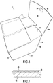
- the isolation device thermal device 1 makes it possible in particular to form an enclosure 2 (see figure 3 ) in which a product to be kept refrigerated for a specified period of time will be transported.
- the thermal insulation device 1 comprises in particular two substantially identical sheets 4.
- Each sheet 4 may be rectangular, and include in particular: an outer face 4a corresponding to the exposed surface of the sheet 4 when the enclosure 2 is formed, an inner face 4b corresponding to the surface of the sheet 4 internally defining the enclosure 2 , an upper edge 4c, a lower edge 4d and two lateral edges 4e.
- the two sheets 4 are superimposed and assembled so that their edges 4c, 4d and 4e are grouped in pairs, with the inner faces 4b of the two sheets facing each other.
- the lateral edges 4e of the two sheets are fixed together in order to connect the side walls which laterally delimit the enclosure 2 for receiving the product to be transported.
- each sheet 4 comprises a set of several layers with specific properties.
- each sheet 4 may comprise a central layer 6 having thermal insulation properties, for example a foamed polyethylene polymer layer, the two faces of which are each covered by a metallized coating 8, for example made of metallized polyethylene terephthalate.
- the metallized coatings 8 make it possible to reflect the radiations, in particular the thermal ones, and thus to limit the thermal exchanges by radiations between the inside and the outside of the enclosure 2.
- the sheet 4 also comprises, on the inner face 4b, a welding film 10 covering the metallized coating 8.
- the welding film 10 may for example be a polyethylene film, and is used in particular to assemble the two sheets 4 of the enclosure 2 by their side edges 4th. More particularly, the two sheets 4 are assembled at their side edges 4e through two welds 12. The welds 12 are made by placing the two side edges 4e in a press, then applying a force and heat on the faces 4a external side edges 4e of the two sheets 4 to assemble them together by their inner faces 4b at which is the welding film 10.
- the welds 12 extend along a portion of the lateral edges 4e, preferably a central portion whose length corresponds to the height of the side walls of the enclosure 4. This produces welds 12 which form an entire edge of the enclosure 2.
- the welds 12 allow not only to assemble the two sheets 4, but also to provide two lines of rigidity facilitating the shaping of the chamber 2 from the thermal insulation device 1 disposed flat. In particular, it is easier to form a substantially cylindrical shape as illustrated in FIG. figure 2 from the thermal insulation device 1 arranged flat as illustrated in FIG. figure 1 .
- the welds 12 make it possible to create a gap between the inside of the enclosure 2 and the outside, in particular at the level of the lateral edges of the enclosure 2.
- the material of the thermal insulation device 1 is found compressed at the side edges of the enclosure 2, either because it is folded or because it is welded.
- the thermal insulation efficiency is lower when the insulating material is compressed, which leads to thermal bridges between the inside and outside of the enclosure 2 at said ridges.
- the welds 12 are chosen so as to create a gap between the inside and the outside of the enclosure 2: the welds 12 are formed by pressing the outer faces 4a of the two sheets 4, so as to the welds 12 protrude on the outer surface of the enclosure 2.
- the welds 12 will thus create an air interface between the thermal insulation device 1 and, for example, the cardboard case in which it will be arranged, which improves the thermal insulation at the lateral edges.
- the welds 12 may for example have a width of about 1 cm.
- each sheet 4 also comprises folding lines 14 and / or cutting lines 16.
- the cutting lines 16 are provided to form at least two flaps 18 on the upper and lower side of each sheet 4.
- the cutting lines 16 are disposed substantially parallel to the welds 12, that is to say perpendicular to the upper edges 4c and lower 4d.
- each sheet 4 has two cutting lines 16 which are both located halfway from the lateral edges 4e: a line extending from the upper edge 4c and a line extending from the lower edge 4d, the two cutting lines 16 being separated by a fold line 14.
- Each cutting line 16 extends over a length substantially equal to one quarter of the distance separating the two lateral edges 4e of the sheet 4, preferably slightly greater.
- each sheet 4 has a fold line 14 disposed between the two cutting lines 16: this fold line 14 is intended to form one of the edges of the enclosure 2.
- each sheet 4 also comprises four other fold lines 14 each corresponding to a flap 18: two fold lines 14 located on the side of the upper edge, and two fold lines 14 located on the lower side. These fold lines 14 are parallel to the upper edges 4c and lower 4d, and extend between a lateral edge 4e and a cutting line 16.
- the flaps 18 are folded to form the enclosure 2.
- the welds 12 then form two lateral edges of the enclosure 2, while the two other edges of the enclosure 2 are formed by a fold line 14.
- An enclosure 2 is thus obtained for receiving a product to be kept cool for a predetermined period of time, and which can be placed in a packaging case, for example a carton, which gives the assembly its mechanical strength.
- the device can be flattened using welds as fold lines, and can be shaped in three dimensions by folding the fold and weld lines to form the enclosure.
- the formatting of the enclosure and its flattening therefore do not modify the welds and do not require forming or removing the welds, which allows easy handling and reuse of the device while having a small footprint for storage .
- thermal insulation device 1 With the thermal insulation device 1 according to the invention, it becomes possible to easily obtain an isothermal packaging to reduce heat exchange between the inside and outside, while remaining small, lightweight and easy to use.
Landscapes
- Engineering & Computer Science (AREA)
- Mechanical Engineering (AREA)
- Packages (AREA)
- Thermal Insulation (AREA)
Claims (12)
- Wärmedämmungsvorrichtung (1) zum Bilden einer Umhüllung (2), die dazu bestimmt ist, ein zu transportierendes Produkt aufzunehmen, wobei die Wärmedämmungsvorrichtung (1) mindestens zwei Lagen (4) umfasst, die jeweils eine Innenseite (4b), die dazu bestimmt ist, zur Innenseite der Umhüllung (2) zu zeigen, und eine Außenseite (4a), die dazu bestimmt ist, zur Außenseite der Umhüllung (2) zu zeigen, aufweisen, wobei die Außen- und Innenseiten jeder Lage (4) durch zwei Seitenkanten (4e) begrenzt sind,
wobei die mindestens zwei Lagen (4) jeweils auf mindestens einer ihrer Flächen metallisiert sind und Falz- (14) und/oder Schneidlinien (16) umfassen, die es ermöglichen, die Umhüllung (2) aus der Wärmedämmungsvorrichtung (1) zu bilden,
wobei die Wärmedämmungsvorrichtung (1) mindestens eine Schweißnaht (12), insbesondere eine thermische Schweißnaht, umfasst, die es ermöglicht, die Seitenkante (4e) zweier benachbarter Lagen (4) miteinander zu verbinden und die dazu bestimmt ist, eine Kante der Umhüllung (2) zu bilden,
dadurch gekennzeichnet, dass die Umhüllung (2) obere und untere Seitenwände und Klappen (18) umfasst, wobei sich die Schweißnaht/-nähte über einen Abschnitt der Seitenkanten erstreckt/erstrecken, der der Höhe der Seitenwände der Umhüllung entspricht,
und dass mindestens eine Lage, vorzugsweise jede Lage der Vorrichtung, mindestens eine Seitenwand, eine obere Klappe und eine untere Klappe bildet, wobei die obere und untere Klappe an zwei gegenüberliegenden Kanten einer Seitenwand durch eine Falzlinie angelenkt sind. - Wärmedämmungsvorrichtung (1) gemäß Anspruch 1, die dazu ausgebildet ist, zusammenfaltbar zu sein, vorzugsweise durch Falzen entlang der mindestens einen Schweißnaht und gegebenenfalls durch Falzen entlang einer oder mehrerer Falzlinien.
- Wärmedämmungsvorrichtung (1) gemäß Anspruch 1 oder 2, wobei die mindestens zwei Lagen (4) jeweils eine geschäumte Polymerschicht (6) und eine metallisierte Beschichtung (8) umfassen.
- Wärmedämmungsvorrichtung (1) gemäß Anspruch 3, wobei die geschäumte Polymerschicht (6) geschäumtes Polyethylen, zum Beispiel Polyethylen niedriger Dichte, umfasst.
- Wärmedämmungsvorrichtung (1) gemäß Anspruch 3 oder 4, wobei die geschäumte Polymerschicht (6) eine Dicke zwischen 1 und 5 mm, vorzugsweise zwischen 2 und 4 mm aufweist.
- Wärmedämmungsvorrichtung (1) gemäß einem der Ansprüche 3 bis 5, wobei die metallisierte Beschichtung (8) einen Film aus metallisiertem Polyethylenterephthalat umfasst.
- Wärmedämmungsvorrichtung (1) gemäß einem der Ansprüche 3 bis 6, wobei die metallisierte Beschichtung (8) auf der Außenseite (4a), vorzugsweise auf der Außenseite (4a) und der Innenseite (4b), der mindestens zwei Lagen (4) vorgesehen ist.
- Wärmedämmungsvorrichtung (1) gemäß einem der vorgenannten Ansprüche, die auch auf mindestens einem Teil der Innenfläche (4b) einen schweißbaren Film (10), zum Beispiel aus Polyethylen, umfasst.
- Wärmedämmungsvorrichtung (1) gemäß einem der vorgenannten Ansprüche, wobei mindestens eine Lage, vorzugsweise jede Lage der Vorrichtung, zwei durch eine Falzlinie getrennte Seitenwände sowie zwei obere und zwei untere Klappen bildet, wobei eine obere und eine untere Klappe an zwei gegenüberliegenden Kanten jeder Seitenwand durch eine Falzlinie angelenkt sind.
- Wärmedämmungsvorrichtung (1) gemäß dem vorgenannten Anspruch, wobei die ungeschweißte Länge der Seitenkanten (4e) so gewählt ist, dass zumindest ein Teil der oberen und/oder unteren Klappen (18) überlappen kann.
- Wärmedämmungsvorrichtung (1) gemäß einem der vorgenannten Ansprüche, umfassend zwei Lagen (4), die einander überlagern und durch ihre beiden Seitenkanten (4e) miteinander verbunden sind, wobei jede Lage (4) zwischen den beiden Seitenkanten (4e) eine Falzlinie (14) umfasst, die im Wesentlichen parallel zu den beiden Seitenkanten (4e) verläuft und dazu bestimmt ist, eine Kante der Umhüllung (2) zu bilden.
- Isothermische Verpackung, umfassend eine Wärmedämmungsvorrichtung (1) gemäß einem der vorgenannten Ansprüche und eine Verpackungsschachtel, zum Beispiel eine Pappschachtel mit einer der Form der Umhüllung (2) ähnlichen allgemeinen Form, in der sich die Umhüllung (2) befindet.
Applications Claiming Priority (1)
| Application Number | Priority Date | Filing Date | Title |
|---|---|---|---|
| FR1659303A FR3056564B1 (fr) | 2016-09-29 | 2016-09-29 | Dispositif d'isolation thermique |
Publications (2)
| Publication Number | Publication Date |
|---|---|
| EP3301040A1 EP3301040A1 (de) | 2018-04-04 |
| EP3301040B1 true EP3301040B1 (de) | 2018-11-07 |
Family
ID=57583262
Family Applications (1)
| Application Number | Title | Priority Date | Filing Date |
|---|---|---|---|
| EP17188240.0A Active EP3301040B1 (de) | 2016-09-29 | 2017-08-29 | Wärmedämmungsvorrichtung |
Country Status (2)
| Country | Link |
|---|---|
| EP (1) | EP3301040B1 (de) |
| FR (1) | FR3056564B1 (de) |
Family Cites Families (3)
| Publication number | Priority date | Publication date | Assignee | Title |
|---|---|---|---|---|
| GB2316669A (en) * | 1996-08-30 | 1998-03-04 | Jiffy Packaging Co Ltd | Heat reflective and impact resistant protective bag |
| AU1456099A (en) * | 1997-11-12 | 1999-05-31 | Thermo Solutions, Inc. | Soft-sided insulated container |
| US20030047564A1 (en) * | 2001-08-31 | 2003-03-13 | Charles Veiseh | Insulated container and methods for making and storing the same |
-
2016
- 2016-09-29 FR FR1659303A patent/FR3056564B1/fr active Active
-
2017
- 2017-08-29 EP EP17188240.0A patent/EP3301040B1/de active Active
Non-Patent Citations (1)
| Title |
|---|
| None * |
Also Published As
| Publication number | Publication date |
|---|---|
| EP3301040A1 (de) | 2018-04-04 |
| FR3056564A1 (fr) | 2018-03-30 |
| FR3056564B1 (fr) | 2020-11-27 |
Similar Documents
| Publication | Publication Date | Title |
|---|---|---|
| EP0236173B1 (de) | Verpackungskiste und deren Herstellungsverfahren | |
| EP2872409B1 (de) | Kastenförmige verpackung aus zwei materialien zum verpacken eines produktes, und herstellungsverfahren | |
| FR2582620A1 (fr) | Emballage en carton pouvant etre referme hermetiquement et flan et base de carton pour sa fabrication | |
| WO2004032633A2 (fr) | Emballage pour la preparation de pop corn dans un four a micro-ondes | |
| FR2948342A1 (fr) | Caisse isotherme se presentant sous la forme d'un kit | |
| EP3301040B1 (de) | Wärmedämmungsvorrichtung | |
| FR2682936A1 (fr) | Conteneur empilable a coins renforces. | |
| FR3008685A1 (fr) | Emballage isotherme ecologique | |
| EP4108584A1 (de) | Verpackung mit einteiligem siegelrand, die aus zwei sich überlappenden zuschnitten hergestellt wird | |
| EP1808383B1 (de) | Verschliessvorrichtung für eine Packung zum Lagern unter Vakuum | |
| EP0326450B1 (de) | Schalenförmige Verpackung aus Karton oder dergleichen | |
| FR2972958A1 (fr) | Procede pour la fabrication d'une barquette bi-composants | |
| FR2911122A1 (fr) | Caisse isotherme a enveloppe metalisee en mousse a cellules fermees | |
| EP2014967B1 (de) | Isolierverpackung | |
| FR2794430A1 (fr) | Flan de carton ou de matiere similaire pour l'obtention d'un emballage ou d'une partie d'emballage et l'emballage obtenu par la mise en volume de ce flan | |
| FR3050182A1 (fr) | Sac isotherme permettant une ouverture de grande amplitude | |
| EP2829486B1 (de) | Verpackung, die ein Element aus halbsteifem Material und eine Wärmeschrumpffolie umfasst, Zuschnitt und Herstellungsverfahren | |
| FR3054208A1 (fr) | Dispositif d'isolation thermique et emballage isotherme comportant un tel dispositif d'isolation | |
| BE889490R (fr) | Boites en carton pour liquides | |
| EP4108585A1 (de) | Einteilige verpackung mit siegelrand, die aus zwei nicht überlappenden zuschnitten hergestellt wird | |
| EP1205296A1 (de) | Verpackungsfilm und damit hergestellte Verpackung | |
| FR2566740A2 (fr) | Perfectionnements au procede de conditionnement parallelepipedique et conditionnement obtenu selon ce procede | |
| FR3052753A1 (fr) | Dispositif de rangement et de conditionnement d'objets | |
| FR2900136A1 (fr) | Emballage isotherme | |
| FR2562870A1 (fr) | Conditionnement resistant a l'humidite, apte a etre obture de facon etanche par un film de matiere plastique |
Legal Events
| Date | Code | Title | Description |
|---|---|---|---|
| PUAI | Public reference made under article 153(3) epc to a published international application that has entered the european phase |
Free format text: ORIGINAL CODE: 0009012 |
|
| STAA | Information on the status of an ep patent application or granted ep patent |
Free format text: STATUS: THE APPLICATION HAS BEEN PUBLISHED |
|
| AK | Designated contracting states |
Kind code of ref document: A1 Designated state(s): AL AT BE BG CH CY CZ DE DK EE ES FI FR GB GR HR HU IE IS IT LI LT LU LV MC MK MT NL NO PL PT RO RS SE SI SK SM TR |
|
| AX | Request for extension of the european patent |
Extension state: BA ME |
|
| STAA | Information on the status of an ep patent application or granted ep patent |
Free format text: STATUS: REQUEST FOR EXAMINATION WAS MADE |
|
| 17P | Request for examination filed |
Effective date: 20180423 |
|
| RBV | Designated contracting states (corrected) |
Designated state(s): AL AT BE BG CH CY CZ DE DK EE ES FI FR GB GR HR HU IE IS IT LI LT LU LV MC MK MT NL NO PL PT RO RS SE SI SK SM TR |
|
| GRAP | Despatch of communication of intention to grant a patent |
Free format text: ORIGINAL CODE: EPIDOSNIGR1 |
|
| STAA | Information on the status of an ep patent application or granted ep patent |
Free format text: STATUS: GRANT OF PATENT IS INTENDED |
|
| RIC1 | Information provided on ipc code assigned before grant |
Ipc: B65D 81/38 20060101AFI20180529BHEP |
|
| INTG | Intention to grant announced |
Effective date: 20180618 |
|
| GRAS | Grant fee paid |
Free format text: ORIGINAL CODE: EPIDOSNIGR3 |
|
| GRAA | (expected) grant |
Free format text: ORIGINAL CODE: 0009210 |
|
| STAA | Information on the status of an ep patent application or granted ep patent |
Free format text: STATUS: THE PATENT HAS BEEN GRANTED |
|
| AK | Designated contracting states |
Kind code of ref document: B1 Designated state(s): AL AT BE BG CH CY CZ DE DK EE ES FI FR GB GR HR HU IE IS IT LI LT LU LV MC MK MT NL NO PL PT RO RS SE SI SK SM TR |
|
| REG | Reference to a national code |
Ref country code: GB Ref legal event code: FG4D Free format text: NOT ENGLISH |
|
| REG | Reference to a national code |
Ref country code: CH Ref legal event code: EP Ref country code: AT Ref legal event code: REF Ref document number: 1061788 Country of ref document: AT Kind code of ref document: T Effective date: 20181115 |
|
| REG | Reference to a national code |
Ref country code: DE Ref legal event code: R096 Ref document number: 602017000836 Country of ref document: DE |
|
| REG | Reference to a national code |
Ref country code: IE Ref legal event code: FG4D Free format text: LANGUAGE OF EP DOCUMENT: FRENCH |
|
| REG | Reference to a national code |
Ref country code: CH Ref legal event code: NV Representative=s name: P&TS SA, CH |
|
| REG | Reference to a national code |
Ref country code: NL Ref legal event code: MP Effective date: 20181107 |
|
| REG | Reference to a national code |
Ref country code: LT Ref legal event code: MG4D |
|
| REG | Reference to a national code |
Ref country code: AT Ref legal event code: MK05 Ref document number: 1061788 Country of ref document: AT Kind code of ref document: T Effective date: 20181107 |
|
| PG25 | Lapsed in a contracting state [announced via postgrant information from national office to epo] |
Ref country code: ES Free format text: LAPSE BECAUSE OF FAILURE TO SUBMIT A TRANSLATION OF THE DESCRIPTION OR TO PAY THE FEE WITHIN THE PRESCRIBED TIME-LIMIT Effective date: 20181107 Ref country code: AT Free format text: LAPSE BECAUSE OF FAILURE TO SUBMIT A TRANSLATION OF THE DESCRIPTION OR TO PAY THE FEE WITHIN THE PRESCRIBED TIME-LIMIT Effective date: 20181107 Ref country code: BG Free format text: LAPSE BECAUSE OF FAILURE TO SUBMIT A TRANSLATION OF THE DESCRIPTION OR TO PAY THE FEE WITHIN THE PRESCRIBED TIME-LIMIT Effective date: 20190207 Ref country code: NO Free format text: LAPSE BECAUSE OF FAILURE TO SUBMIT A TRANSLATION OF THE DESCRIPTION OR TO PAY THE FEE WITHIN THE PRESCRIBED TIME-LIMIT Effective date: 20190207 Ref country code: LT Free format text: LAPSE BECAUSE OF FAILURE TO SUBMIT A TRANSLATION OF THE DESCRIPTION OR TO PAY THE FEE WITHIN THE PRESCRIBED TIME-LIMIT Effective date: 20181107 Ref country code: IS Free format text: LAPSE BECAUSE OF FAILURE TO SUBMIT A TRANSLATION OF THE DESCRIPTION OR TO PAY THE FEE WITHIN THE PRESCRIBED TIME-LIMIT Effective date: 20190307 Ref country code: FI Free format text: LAPSE BECAUSE OF FAILURE TO SUBMIT A TRANSLATION OF THE DESCRIPTION OR TO PAY THE FEE WITHIN THE PRESCRIBED TIME-LIMIT Effective date: 20181107 Ref country code: LV Free format text: LAPSE BECAUSE OF FAILURE TO SUBMIT A TRANSLATION OF THE DESCRIPTION OR TO PAY THE FEE WITHIN THE PRESCRIBED TIME-LIMIT Effective date: 20181107 Ref country code: HR Free format text: LAPSE BECAUSE OF FAILURE TO SUBMIT A TRANSLATION OF THE DESCRIPTION OR TO PAY THE FEE WITHIN THE PRESCRIBED TIME-LIMIT Effective date: 20181107 |
|
| PG25 | Lapsed in a contracting state [announced via postgrant information from national office to epo] |
Ref country code: NL Free format text: LAPSE BECAUSE OF FAILURE TO SUBMIT A TRANSLATION OF THE DESCRIPTION OR TO PAY THE FEE WITHIN THE PRESCRIBED TIME-LIMIT Effective date: 20181107 Ref country code: SE Free format text: LAPSE BECAUSE OF FAILURE TO SUBMIT A TRANSLATION OF THE DESCRIPTION OR TO PAY THE FEE WITHIN THE PRESCRIBED TIME-LIMIT Effective date: 20181107 Ref country code: RS Free format text: LAPSE BECAUSE OF FAILURE TO SUBMIT A TRANSLATION OF THE DESCRIPTION OR TO PAY THE FEE WITHIN THE PRESCRIBED TIME-LIMIT Effective date: 20181107 Ref country code: AL Free format text: LAPSE BECAUSE OF FAILURE TO SUBMIT A TRANSLATION OF THE DESCRIPTION OR TO PAY THE FEE WITHIN THE PRESCRIBED TIME-LIMIT Effective date: 20181107 Ref country code: PT Free format text: LAPSE BECAUSE OF FAILURE TO SUBMIT A TRANSLATION OF THE DESCRIPTION OR TO PAY THE FEE WITHIN THE PRESCRIBED TIME-LIMIT Effective date: 20190307 Ref country code: GR Free format text: LAPSE BECAUSE OF FAILURE TO SUBMIT A TRANSLATION OF THE DESCRIPTION OR TO PAY THE FEE WITHIN THE PRESCRIBED TIME-LIMIT Effective date: 20190208 |
|
| PG25 | Lapsed in a contracting state [announced via postgrant information from national office to epo] |
Ref country code: CZ Free format text: LAPSE BECAUSE OF FAILURE TO SUBMIT A TRANSLATION OF THE DESCRIPTION OR TO PAY THE FEE WITHIN THE PRESCRIBED TIME-LIMIT Effective date: 20181107 Ref country code: DK Free format text: LAPSE BECAUSE OF FAILURE TO SUBMIT A TRANSLATION OF THE DESCRIPTION OR TO PAY THE FEE WITHIN THE PRESCRIBED TIME-LIMIT Effective date: 20181107 Ref country code: PL Free format text: LAPSE BECAUSE OF FAILURE TO SUBMIT A TRANSLATION OF THE DESCRIPTION OR TO PAY THE FEE WITHIN THE PRESCRIBED TIME-LIMIT Effective date: 20181107 Ref country code: IT Free format text: LAPSE BECAUSE OF FAILURE TO SUBMIT A TRANSLATION OF THE DESCRIPTION OR TO PAY THE FEE WITHIN THE PRESCRIBED TIME-LIMIT Effective date: 20181107 |
|
| REG | Reference to a national code |
Ref country code: DE Ref legal event code: R097 Ref document number: 602017000836 Country of ref document: DE |
|
| PG25 | Lapsed in a contracting state [announced via postgrant information from national office to epo] |
Ref country code: SK Free format text: LAPSE BECAUSE OF FAILURE TO SUBMIT A TRANSLATION OF THE DESCRIPTION OR TO PAY THE FEE WITHIN THE PRESCRIBED TIME-LIMIT Effective date: 20181107 Ref country code: RO Free format text: LAPSE BECAUSE OF FAILURE TO SUBMIT A TRANSLATION OF THE DESCRIPTION OR TO PAY THE FEE WITHIN THE PRESCRIBED TIME-LIMIT Effective date: 20181107 Ref country code: EE Free format text: LAPSE BECAUSE OF FAILURE TO SUBMIT A TRANSLATION OF THE DESCRIPTION OR TO PAY THE FEE WITHIN THE PRESCRIBED TIME-LIMIT Effective date: 20181107 Ref country code: SM Free format text: LAPSE BECAUSE OF FAILURE TO SUBMIT A TRANSLATION OF THE DESCRIPTION OR TO PAY THE FEE WITHIN THE PRESCRIBED TIME-LIMIT Effective date: 20181107 |
|
| PLBE | No opposition filed within time limit |
Free format text: ORIGINAL CODE: 0009261 |
|
| STAA | Information on the status of an ep patent application or granted ep patent |
Free format text: STATUS: NO OPPOSITION FILED WITHIN TIME LIMIT |
|
| 26N | No opposition filed |
Effective date: 20190808 |
|
| PG25 | Lapsed in a contracting state [announced via postgrant information from national office to epo] |
Ref country code: TR Free format text: LAPSE BECAUSE OF FAILURE TO SUBMIT A TRANSLATION OF THE DESCRIPTION OR TO PAY THE FEE WITHIN THE PRESCRIBED TIME-LIMIT Effective date: 20181107 |
|
| PG25 | Lapsed in a contracting state [announced via postgrant information from national office to epo] |
Ref country code: CY Free format text: LAPSE BECAUSE OF FAILURE TO SUBMIT A TRANSLATION OF THE DESCRIPTION OR TO PAY THE FEE WITHIN THE PRESCRIBED TIME-LIMIT Effective date: 20181107 |
|
| PG25 | Lapsed in a contracting state [announced via postgrant information from national office to epo] |
Ref country code: HU Free format text: LAPSE BECAUSE OF FAILURE TO SUBMIT A TRANSLATION OF THE DESCRIPTION OR TO PAY THE FEE WITHIN THE PRESCRIBED TIME-LIMIT; INVALID AB INITIO Effective date: 20170829 Ref country code: MT Free format text: LAPSE BECAUSE OF FAILURE TO SUBMIT A TRANSLATION OF THE DESCRIPTION OR TO PAY THE FEE WITHIN THE PRESCRIBED TIME-LIMIT Effective date: 20181107 |
|
| PG25 | Lapsed in a contracting state [announced via postgrant information from national office to epo] |
Ref country code: SI Free format text: LAPSE BECAUSE OF FAILURE TO SUBMIT A TRANSLATION OF THE DESCRIPTION OR TO PAY THE FEE WITHIN THE PRESCRIBED TIME-LIMIT Effective date: 20181107 |
|
| PGFP | Annual fee paid to national office [announced via postgrant information from national office to epo] |
Ref country code: IE Payment date: 20210719 Year of fee payment: 5 Ref country code: LU Payment date: 20210716 Year of fee payment: 5 Ref country code: MC Payment date: 20210723 Year of fee payment: 5 |
|
| PGFP | Annual fee paid to national office [announced via postgrant information from national office to epo] |
Ref country code: GB Payment date: 20210819 Year of fee payment: 5 Ref country code: DE Payment date: 20210811 Year of fee payment: 5 |
|
| PG25 | Lapsed in a contracting state [announced via postgrant information from national office to epo] |
Ref country code: MK Free format text: LAPSE BECAUSE OF FAILURE TO SUBMIT A TRANSLATION OF THE DESCRIPTION OR TO PAY THE FEE WITHIN THE PRESCRIBED TIME-LIMIT Effective date: 20181107 |
|
| REG | Reference to a national code |
Ref country code: DE Ref legal event code: R119 Ref document number: 602017000836 Country of ref document: DE |
|
| REG | Reference to a national code |
Ref country code: DE Ref legal event code: R082 Ref document number: 602017000836 Country of ref document: DE Representative=s name: CBDL PATENTANWAELTE GBR, DE |
|
| PG25 | Lapsed in a contracting state [announced via postgrant information from national office to epo] |
Ref country code: MC Free format text: LAPSE BECAUSE OF NON-PAYMENT OF DUE FEES Effective date: 20220831 |
|
| GBPC | Gb: european patent ceased through non-payment of renewal fee |
Effective date: 20220829 |
|
| PG25 | Lapsed in a contracting state [announced via postgrant information from national office to epo] |
Ref country code: LU Free format text: LAPSE BECAUSE OF NON-PAYMENT OF DUE FEES Effective date: 20220829 |
|
| PG25 | Lapsed in a contracting state [announced via postgrant information from national office to epo] |
Ref country code: IE Free format text: LAPSE BECAUSE OF NON-PAYMENT OF DUE FEES Effective date: 20220829 Ref country code: DE Free format text: LAPSE BECAUSE OF NON-PAYMENT OF DUE FEES Effective date: 20230301 |
|
| PG25 | Lapsed in a contracting state [announced via postgrant information from national office to epo] |
Ref country code: GB Free format text: LAPSE BECAUSE OF NON-PAYMENT OF DUE FEES Effective date: 20220829 |
|
| PGFP | Annual fee paid to national office [announced via postgrant information from national office to epo] |
Ref country code: BE Payment date: 20250829 Year of fee payment: 9 |
|
| PGFP | Annual fee paid to national office [announced via postgrant information from national office to epo] |
Ref country code: FR Payment date: 20250825 Year of fee payment: 9 |
|
| PGFP | Annual fee paid to national office [announced via postgrant information from national office to epo] |
Ref country code: CH Payment date: 20250930 Year of fee payment: 9 |