EP3301043A1 - Sac de transport pour convoyeur suspendu - Google Patents
Sac de transport pour convoyeur suspendu Download PDFInfo
- Publication number
- EP3301043A1 EP3301043A1 EP17182935.1A EP17182935A EP3301043A1 EP 3301043 A1 EP3301043 A1 EP 3301043A1 EP 17182935 A EP17182935 A EP 17182935A EP 3301043 A1 EP3301043 A1 EP 3301043A1
- Authority
- EP
- European Patent Office
- Prior art keywords
- side wall
- transport
- contact surface
- adhesive contact
- transport bag
- Prior art date
- Legal status (The legal status is an assumption and is not a legal conclusion. Google has not performed a legal analysis and makes no representation as to the accuracy of the status listed.)
- Granted
Links
Images




Classifications
-
- B—PERFORMING OPERATIONS; TRANSPORTING
- B65—CONVEYING; PACKING; STORING; HANDLING THIN OR FILAMENTARY MATERIAL
- B65G—TRANSPORT OR STORAGE DEVICES, e.g. CONVEYORS FOR LOADING OR TIPPING, SHOP CONVEYOR SYSTEMS OR PNEUMATIC TUBE CONVEYORS
- B65G9/00—Apparatus for assisting manual handling having suspended load-carriers movable by hand or gravity
- B65G9/002—Load-carriers, rollers therefor
-
- B—PERFORMING OPERATIONS; TRANSPORTING
- B65—CONVEYING; PACKING; STORING; HANDLING THIN OR FILAMENTARY MATERIAL
- B65D—CONTAINERS FOR STORAGE OR TRANSPORT OF ARTICLES OR MATERIALS, e.g. BAGS, BARRELS, BOTTLES, BOXES, CANS, CARTONS, CRATES, DRUMS, JARS, TANKS, HOPPERS, FORWARDING CONTAINERS; ACCESSORIES, CLOSURES, OR FITTINGS THEREFOR; PACKAGING ELEMENTS; PACKAGES
- B65D33/00—Details of, or accessories for, sacks or bags
- B65D33/02—Local reinforcements or stiffening inserts, e.g. wires, strings, strips or frames
-
- B—PERFORMING OPERATIONS; TRANSPORTING
- B65—CONVEYING; PACKING; STORING; HANDLING THIN OR FILAMENTARY MATERIAL
- B65D—CONTAINERS FOR STORAGE OR TRANSPORT OF ARTICLES OR MATERIALS, e.g. BAGS, BARRELS, BOTTLES, BOXES, CANS, CARTONS, CRATES, DRUMS, JARS, TANKS, HOPPERS, FORWARDING CONTAINERS; ACCESSORIES, CLOSURES, OR FITTINGS THEREFOR; PACKAGING ELEMENTS; PACKAGES
- B65D33/00—Details of, or accessories for, sacks or bags
- B65D33/14—Suspension means
-
- B—PERFORMING OPERATIONS; TRANSPORTING
- B65—CONVEYING; PACKING; STORING; HANDLING THIN OR FILAMENTARY MATERIAL
- B65G—TRANSPORT OR STORAGE DEVICES, e.g. CONVEYORS FOR LOADING OR TIPPING, SHOP CONVEYOR SYSTEMS OR PNEUMATIC TUBE CONVEYORS
- B65G19/00—Conveyors comprising an impeller or a series of impellers carried by an endless traction element and arranged to move articles or materials over a supporting surface or underlying material, e.g. endless scraper conveyors
- B65G19/02—Conveyors comprising an impeller or a series of impellers carried by an endless traction element and arranged to move articles or materials over a supporting surface or underlying material, e.g. endless scraper conveyors for articles, e.g. for containers
- B65G19/025—Conveyors comprising an impeller or a series of impellers carried by an endless traction element and arranged to move articles or materials over a supporting surface or underlying material, e.g. endless scraper conveyors for articles, e.g. for containers for suspended articles
Definitions
- the invention relates to a transport bag for a suspended conveyor.
- a transport bag for a suspended conveyor is from the DE 10 2008 026 720 A1 known.
- the transport bag has a flexible bag material, so that the shape of the bag changes depending on the goods contained therein.
- a back pressure can act on the stowed transport bags.
- the back pressure is caused, for example, by a downhill force in the storage area or by a staging system.
- Transport bags which are bulged because of the transported goods, can slip and / or get caught transversely to the transport direction.
- the bag transport with the overhead conveyor is error-prone.
- DE 10 2010 053 590 A1 known to provide spacers between the individual transport bags to comply with a defined minimum distance between adjacent transport pockets along the transport direction.
- the adhesive contact surface is at least partially formed on an outer side of a front side wall and / or a rear side wall.
- the side walls are in particular made of a limp and / or bulky material. Such a material is for example a textile fabric or textile fleece. In particular, the side walls are not rigid.
- the adhesive contact surface of the transport bag can rest on the adjacent transport bag, either directly on the bag material or on an adhesive contact surface of the adjacent transport bag. In the area of the adhesive contact surface, the transport bag is detachably adhering to the adjacent transport bag.
- the adhesive force is in particular greater than a resulting displacement force, which is oriented in particular transversely and in particular perpendicular to a conveying direction of the overhead conveyor.
- the resulting displacement force is caused in particular by the back pressure.
- the transport bag has a substantially cuboid shape with a front side wall oriented in the transport direction of the overhead conveyor, an opposite rear side wall and a bottom wall connecting the front side wall with the rear side wall.
- the transport bag according to the invention can be reliably arranged in a jam section. A lateral displacement of the transport bags as a result of a priori unknown back pressure is excluded.
- the transport bag is only partially formed with the adhesive contact surface.
- the adhesive contact surface is arranged in particular there on the transport bag, where expected adjacent transport bags contact each other when the transport bags are stowed in the storage area of the piling conveyor. It is also conceivable that the adhesive contact surface extends over the entire front side wall and / or the entire rear side wall and in particular over the entire transport pocket. In this case, the transport bag could be made uniformly from a material forming the adhesive contact surface. The uniform material prevents lateral slipping of the transport bags.
- spacers according to the DE 10 2010 053 590 A1 can be waived if the transport bags themselves are designed so that lateral slipping is excluded. Due to the adhesive contact surface, a stable arrangement of a plurality of transport pockets in a buffer path is possible substantially independently of the back pressure. The damming of the transport bags is reliably possible with reduced effort. The transport bags are reliable, error-prone and easy to arrange along a jam track.
- the embodiment of the adhesive contact surface according to claim 2 allows a particularly reliable avoidance of the lateral displacement. Adjacent transport bags are held directly adjacent to each other in the area of the adhesive contact surface. A lateral evasion is avoided.
- the design of a transport bag according to claim 3 ensures reliable storage of transport bags in a storage area.
- the coefficient of friction of the friction lining is higher than in the case of typical pocket materials which have a coefficient of friction of, for example, up to 0.4.
- the friction lining is in particular made of polyvinyl chloride (PVC), in particular made of soft PVC (PVC-P).
- PVC polyvinyl chloride
- PVC-P soft PVC
- As a coefficient of friction in the context of the application in particular the sliding friction coefficient for a dry, so not lubricated material pairing, in particular the material for the friction lining against steel understood. For example, this value is 0.6 for PVC.
- the coefficient of friction ie the coefficient of friction, depending on speed and / or temperature, for example, between about 0.8 and 2.5 are.
- a typical rubber material is, for example, acrylonitrile-butadiene (NBR).
- NBR acrylonitrile-butadiene
- As a material for the friction lining for example, silicone rubber and / or acrylic rubber into consideration.
- a coefficient of friction which is greater than 1 allows a particularly high adhesion.
- the design of the transport bag according to claim 4 allows efficient use of the friction material.
- the friction lining is placed in particular on one of the side walls or integrated therein.
- a transport bag according to claim 5 has advantageous safety properties, in particular with regard to a possible risk of fire on.
- the design of the transport bag according to claim 6 allows a mechanical controlled connection of adjacent transport bags.
- the adhesive contact surface has in particular a surface structuring.
- the adhesive contact surface has in particular at least one elevation and / or one depression.
- the at least one depression can in particular be designed by a gap formed between the elevations of the adhesive contact surface.
- the elevations are arranged in the form of a grid on the adhesive contact surface, so that the recesses formed therebetween are formed in a grid shape.
- Concerns adjacent transport bags can engage the elevations of the adhesive contact surface of a pocket in the recesses of the adhesive contact surface of the other transport bag and there form a mechanical, in particular by positive engagement, connection and prevent lateral displacement of the transport bags.
- the elevations may be, for example, pyramidal, conical, cuboidal and / or cylindrical. The elevations and / or depressions allow snagging each other. The adhesion of the transport bags to each other is thereby improved.
- the survey may for example be designed as protruding on the adhesive contact surface mandrel, which can engage in a rounded slot as a recess of the adjacent transport pocket as a counter contour.
- Adherence of adjacent transport pockets is improved when depressions of the adhesive contact surface of one transport pocket directly interact with corresponding elevations of the adhesive contact surface of the other transport pocket.
- elevations and depressions are arranged on an adhesive contact surface of a transport pocket next to one another in a, in particular regular, grid. It is advantageous if the respective grid spacings of elevations and depressions of the corresponding adhesive contact surfaces are identical. It is also advantageous if the respective contour of the elevations interacts with the respective contour of the corresponding depressions.
- the depressions each represent a negative of a survey.
- the elevations and depressions increase the surface area of the contact surface.
- the enlarged surface allows improved adhesion of the adjacent transport pockets to each other.
- the adhesive contact surface also allows for improved adhesion when the adjacent transport bag is designed without elevations and / or depressions.
- the elevations and / or depressions of the adhesive contact surface are elastically deformed by the application to the adjacent transport pocket. A lateral slippage due to the back pressure is prevented.
- a friction lining made of a friction material is provided on the adhesive contact surface, wherein the friction lining has elevations and / or depressions.
- the adhesion is additionally improved.
- the adhesive contact surface allows a holding force due to adhesion by friction and due to positive engagement by surveys and / or depressions.
- a stiffening plate according to claim 7 ensures additional mechanical stabilization of the transport bag.
- the stiffening plate ensures a substantially defined planar contact surface of the transport bag, in particular independent of the loaded goods.
- the design of the transport bag according to claim 8 allows a particularly robust and compact design.
- the multi-layer design ensures that the outer adhesive contact surface is supported by the underlying stiffening plate. This avoids that the adhesive contact surface curves undefined and / or deformed as a result of the loading of the transport bag.
- An embodiment of the transport bag according to claim 9 ensures a stiffening of the adhesive contact surface.
- the stiffening plate may for example be made of cardboard or cardboard.
- the stiffening plate may have a perpendicular to the plate plane oriented hollow chamber.
- the hollow chambers may for example be honeycomb-shaped.
- the hollow chambers may also have a different contour, for example an annular or rectangular or square contour.
- the stiffening plate can also be made of a different material such as plastic and in particular polypropylene. It is also conceivable to use a stiffening plate made of metal, in particular of metal foam material.
- An embodiment of the transport bag according to claim 11 ensures a faultless stiffening of the adhesive contact surface.
- An embodiment of a transport bag according to claim 12 increases the security of conveying the transport bags.
- the liability of the transport bags together and thus the security against lateral slippage are additionally increased.
- the adhesive contact surfaces are made identical, wherein the adhesive contact surfaces may differ with respect to their dimensions and / or their arrangement.
- the front adhesive contact surface is assigned to the front side wall closer to the bottom wall than the rear adhesive contact surface, which is in contact with the adhesive contact surface of the subsequent, as a result of a slope of the conveyor rail in the storage area higher downstream transport bag.
- a transport bag according to claim 13 enables improved and in particular detachable adhesion of the adjacent transport bags to each other.
- an adhesive element which is formed magnetically and / or as Velcro.
- the execution of the transport bag according to claim 14 allows an advantageous suspension on a conveyor rail of the overhead conveyor.
- dam 1 is part of a suspended conveyor.
- the jam section 1 has an upper conveyor rail 2, which is arranged inclined relative to the horizontal 3 with an inclination angle n.
- the jam section 1 has a switchable stopper element 4 in order to stop transport pockets 5 which are transported along the conveyor rail 2.
- the transport bags 5 are each guided on an adapter element 6 guided along the conveyor rail 2.
- the conveyor rail 2 specifies a transport direction 7.
- each transport goods 8 are arranged.
- the transport goods 8 in particular have different sizes.
- the transport goods 8 have an oriented along the transport direction 7 Thickness that is greater than the initial thickness of the transport bag 5 in the unloaded state.
- the transport pockets 5 are arranged with the adapter elements 6 at substantially the same distance from the conveyor rail 2.
- the distance between the transport pockets 5 results directly from the loading.
- the transport bags can be arranged at different distances from each other. The distance corresponds approximately to the bag width in the loaded state. Due to the baggy shape of the transport bags 5, these are adjacent to each other.
- the transport pockets 5 arranged further back are arranged substantially unsatisfied with respect to the vertical 9.
- the transport bags 5 each have 2 adhesive contact surfaces 10.
- the adhesive contact surfaces 10 of two adjacent arranged transport pockets 5 abut each other. This prevents the transport pockets 5 from being displaced as a result of the dynamic pressure along a transverse direction 11, which is oriented perpendicular to the transport direction 7.
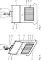
- the transport bag 5 has a front side wall 12, a rear side wall 13 and a bottom wall 14 connecting the front side wall 12 to the rear side wall 13.
- the front side wall 12, the rear side wall 13 and the bottom wall 14 are made of a uniform, flexible bag material executed.
- the front side wall 12 and the rear side wall 13 are attached to two opposite brackets 15.
- the rear side wall 13 has a coupling unit 16 with a hook element 17 for hooking on the adapter element 6.
- the adapter element 6 is in particular a roll adapter, which constitutes a conveyor unit.
- the transport pocket 5 has lateral compensation elements 18 which allow the pocket to be widened in the thickness direction.
- the thickness D of the transport pocket 5 in the unloaded initial state is in Fig. 6 shown.
- the adhesive contact surfaces 10 are arranged at the transport pocket 5 on each outer side of the front side wall 12 and the rear side wall 13.
- the adhesive contact surfaces 10 are executed according to the embodiment shown as a friction lining of PVC-P.
- the adhesive contact surfaces 10 on the front side wall 12 and the rear side wall 13 are in particular designed identically and differ in particular only with regard to their positioning on the front side wall 12 and the rear side wall 13.
- the friction linings 18 each have a surface structuring which, in FIGS. 7 and 8 is shown in more detail.
- the surface structuring of the adhesive contact surface 10 can also be embodied, for example, in that the adhesive contact surface 10 is corrugated, concave or convex.
- a stiffening plate according to the embodiment shown as a polypropylene hollow chamber web plate is executed, arranged.
- the size of the stiffening plate 19 substantially corresponds to the size of the friction lining 18, so that the friction lining 18 is substantially stiffened over the entire surface by the stiffening plate 19.
- the stiffening plate 19 has a width of 200 mm and a height of 300 mm.
- the rectangular surface of the stiffening plate 19, which is defined by its height and width, is in particular slightly smaller than the surface of the friction lining 18, so the adhesive contact surface. This ensures that the stiffening plate 19 is completely covered by the friction lining 18.
- the stiffening plate 19 has a thickness of 3.0 mm.
- the dimensions of the stiffening plate 19 and / or the friction lining 18 can also be selected larger or smaller. In particular, the dimensions of the stiffening plate 19 and / or the friction lining 18 to the size of the transport pocket, so the height and width of the side walls 12, 13, adapted.
- Fig. 7 shows an enlarged detail of the friction lining 18 with a plurality of pyramidal elevations 20.
- the elevations 20 are arranged in a grid in rows and columns. Both in the row and in the column direction in each case a gap 21 between the elevations 20 is formed.
- the gaps 21 form recesses between the elevations 20.
- the adhesion of adjoining transport bags 5 in a storage area 1 can be improved by the elevations 20 of an adhesive contact surface in the interstices 21 of the adhesive contact surface 10 of the adjacent transport pocket engage (see. Fig. 8 ).
- the holding force or adhesive force of the adjoining transport bags is thereby increased.
- the gaps 21 may have a width of 0.5 mm to 1 mm and a depth of about 0.5 mm.
- the material thickness of the transport pocket 5 is about 1.5 mm.
- the transport bag 5 is made of several layers, with the externally disposed adhesive contact surface 10 of the friction lining 18, the underlying arranged stiffening plate 19 and the pocket material arranged underneath.
- the bag material is a flexible textile fabric.
- width and height can be, for example, several millimeters, in particular between 5 mm and 50 mm. Accordingly, the width of the slot-shaped depression is formed.
- the material having the adhesive contact surface 10 has in particular restoring properties, that is, in particular completely elastic, so that after removal of the transport goods 8 from the transport bag 5 this again assumes the initial shape according to the unloaded initial state.
- the friction lining 18 is in particular made of an elastomeric material. It is also conceivable to integrate the stiffening plate 19 in the friction lining 18, in which the stiffening plate 19 is overmolded by the material of the friction lining 18.
Landscapes
- Engineering & Computer Science (AREA)
- Mechanical Engineering (AREA)
- Bag Frames (AREA)
- Purses, Travelling Bags, Baskets, Or Suitcases (AREA)
Applications Claiming Priority (1)
| Application Number | Priority Date | Filing Date | Title |
|---|---|---|---|
| DE102016218879 | 2016-09-29 |
Publications (2)
| Publication Number | Publication Date |
|---|---|
| EP3301043A1 true EP3301043A1 (fr) | 2018-04-04 |
| EP3301043B1 EP3301043B1 (fr) | 2020-01-29 |
Family
ID=59409197
Family Applications (1)
| Application Number | Title | Priority Date | Filing Date |
|---|---|---|---|
| EP17182935.1A Active EP3301043B1 (fr) | 2016-09-29 | 2017-07-25 | Sac de transport pour convoyeur suspendu |
Country Status (4)
| Country | Link |
|---|---|
| US (1) | US20180086563A1 (fr) |
| EP (1) | EP3301043B1 (fr) |
| DE (1) | DE102017212720A1 (fr) |
| ES (1) | ES2774704T3 (fr) |
Cited By (1)
| Publication number | Priority date | Publication date | Assignee | Title |
|---|---|---|---|---|
| EP4613674A1 (fr) | 2024-03-08 | 2025-09-10 | Ferag Ag | Dispositif et procédé pour charger et décharger des unités de transport d'un système de transport suspendu |
Families Citing this family (6)
| Publication number | Priority date | Publication date | Assignee | Title |
|---|---|---|---|---|
| CH710650A1 (de) * | 2015-01-26 | 2016-07-29 | Ferag Ag | Transportvorrichtung, insbesondere in Form eines Hängeförderers. |
| DE202017100206U1 (de) * | 2017-01-16 | 2018-04-17 | Tgw Mechanics Gmbh | Fördergutbehälter mit Auswerfvorrichtung und zugehörige Hängefördervorrichtung |
| AT520517B1 (de) * | 2018-04-13 | 2019-05-15 | Tgw Mechanics Gmbh | Entladestation und Verfahren zum Entladen eines mit einem Fördergut beladenen Fördergutbehälters |
| AT521961B1 (de) * | 2019-01-25 | 2020-07-15 | Tgw Mechanics Gmbh | Fördergutbehälter für eine Hängefördervorrichtung und Entladestation zum Entladen desselben |
| DE102021002833A1 (de) * | 2021-06-02 | 2021-08-12 | Paul Janzen | Transporttasche zum hängenden Transport von Fördergut sowie Beladestation und Förderanlage für diese Transporttaschen |
| CH721145A1 (de) | 2023-09-21 | 2025-03-31 | Ferag Ag | Vorrichtung, verfahren und system zum stabilisieren und beladen von transporttaschen |
Citations (7)
| Publication number | Priority date | Publication date | Assignee | Title |
|---|---|---|---|---|
| DE9312749U1 (de) * | 1993-08-26 | 1993-11-04 | Merten, Helmut Wolfgang, 20255 Hamburg | Umhüllung |
| DE29915385U1 (de) * | 1999-08-19 | 1999-12-09 | F + B Verpackungen GmbH, 97753 Karlstadt | Papier- oder Kunststoffsack mit rutschhemmender Beschichtung |
| US6471402B1 (en) * | 2001-11-05 | 2002-10-29 | Jeff Burns | Formed stacking element integral with plastic storage bags |
| DE102004018569A1 (de) * | 2004-04-16 | 2005-11-03 | Gärtner, Franz | Sammeleinrichtung zum sortierenden Sammeln von Objekten sowie Fördervorrichtung zum Transport der Sammeleinrichtung |
| DE102012018925A1 (de) * | 2012-09-18 | 2014-03-20 | SSI Schäfer PEEM GmbH | Tasche für Hängeförderer, Beladestation, Entladestation und Taschen-Hängeförderanlage |
| US20150036952A1 (en) * | 2013-08-05 | 2015-02-05 | Standard Multiwall Bag Manufacturing Co., | Bulk Materials Bag Having Anti-Skid Treatment and Method of Applying Treatment |
| EP3028961A1 (fr) * | 2014-12-04 | 2016-06-08 | Vanderlande Industries B.V. | Sac de transport pour une marchandise dans une installation de transport de marchandise suspendue |
Family Cites Families (2)
| Publication number | Priority date | Publication date | Assignee | Title |
|---|---|---|---|---|
| DE102008026720A1 (de) | 2008-06-04 | 2009-12-10 | Dürkopp Adler AG | Transport-Tasche und Förder-Anlage für eine Transport-Tasche |
| DE102010053590B4 (de) | 2010-12-06 | 2019-03-07 | Dürkopp Fördertechnik GmbH | Tragetasche für Fördergut und Förderanlage für eine Tragetasche |
-
2017
- 2017-07-25 EP EP17182935.1A patent/EP3301043B1/fr active Active
- 2017-07-25 DE DE102017212720.1A patent/DE102017212720A1/de not_active Withdrawn
- 2017-07-25 ES ES17182935T patent/ES2774704T3/es active Active
- 2017-09-28 US US15/718,287 patent/US20180086563A1/en not_active Abandoned
Patent Citations (7)
| Publication number | Priority date | Publication date | Assignee | Title |
|---|---|---|---|---|
| DE9312749U1 (de) * | 1993-08-26 | 1993-11-04 | Merten, Helmut Wolfgang, 20255 Hamburg | Umhüllung |
| DE29915385U1 (de) * | 1999-08-19 | 1999-12-09 | F + B Verpackungen GmbH, 97753 Karlstadt | Papier- oder Kunststoffsack mit rutschhemmender Beschichtung |
| US6471402B1 (en) * | 2001-11-05 | 2002-10-29 | Jeff Burns | Formed stacking element integral with plastic storage bags |
| DE102004018569A1 (de) * | 2004-04-16 | 2005-11-03 | Gärtner, Franz | Sammeleinrichtung zum sortierenden Sammeln von Objekten sowie Fördervorrichtung zum Transport der Sammeleinrichtung |
| DE102012018925A1 (de) * | 2012-09-18 | 2014-03-20 | SSI Schäfer PEEM GmbH | Tasche für Hängeförderer, Beladestation, Entladestation und Taschen-Hängeförderanlage |
| US20150036952A1 (en) * | 2013-08-05 | 2015-02-05 | Standard Multiwall Bag Manufacturing Co., | Bulk Materials Bag Having Anti-Skid Treatment and Method of Applying Treatment |
| EP3028961A1 (fr) * | 2014-12-04 | 2016-06-08 | Vanderlande Industries B.V. | Sac de transport pour une marchandise dans une installation de transport de marchandise suspendue |
Cited By (1)
| Publication number | Priority date | Publication date | Assignee | Title |
|---|---|---|---|---|
| EP4613674A1 (fr) | 2024-03-08 | 2025-09-10 | Ferag Ag | Dispositif et procédé pour charger et décharger des unités de transport d'un système de transport suspendu |
Also Published As
| Publication number | Publication date |
|---|---|
| EP3301043B1 (fr) | 2020-01-29 |
| DE102017212720A1 (de) | 2018-03-29 |
| ES2774704T3 (es) | 2020-07-22 |
| US20180086563A1 (en) | 2018-03-29 |
Similar Documents
| Publication | Publication Date | Title |
|---|---|---|
| EP3301043A1 (fr) | Sac de transport pour convoyeur suspendu | |
| DE102011003999A1 (de) | Palette | |
| WO2014005991A1 (fr) | Élévateur à godets présentant une courroie protégée par ligne de godets | |
| DE102018122451A1 (de) | Elastisches Transportband für ein Transportsystem, Antriebswalze zum Antrieb des Transportbandes, Transportsystem, Verfahren zur Herstellung der Antriebswalze | |
| WO2019149335A1 (fr) | Boîtier pour un magasin de cartouches pour arme de poing et magasin de cartouches pour arme de poing | |
| DE2602613C3 (de) | Förderband mit gewellten Seitenwänden | |
| EP3650366A1 (fr) | Insert pour un récipient et système de récipients dotés d'un tel insert | |
| DE102011002484B4 (de) | Förderung von Tabakgut | |
| DE10319504B4 (de) | Fördereinrichtung an einem Fracht-Deck eines Flugzeugs | |
| DE102011005397A1 (de) | Matte für den Transport von mindestens einem Gegenstand, Übergabevorrichtung und Verfahren zur Übergabe | |
| DE102023204178A1 (de) | Kettenglied für eine kurvengängige Förderkette, kurvengängige Förderkette und Transfersystem mit kurvengängiger Förderkette | |
| DE102016218319A1 (de) | Aufnahmevorrichtung zum Greifen eines Objektes | |
| DE102013224034A1 (de) | Entladevorrichtung für in einem Transportbehälter angeordnete Güter und Verfahren zum Be- und Entladen solcher Güter | |
| DE202014104805U1 (de) | Transportmittel sowie Transport- und Verteilersystem | |
| DE202016105152U1 (de) | Transportbehälter | |
| DE102013002736A1 (de) | Transportbehälter | |
| EP3663230A1 (fr) | Conteneur de transport | |
| DE102018116347A1 (de) | Elastisches Transportband und Transportsystem | |
| DE202014104279U1 (de) | Falt- und Fixierungssystem zur Sicherung der Bewegung von ein- oder mehrschichtigen Einlegezellen in Verpackungen für den Warentransport | |
| DE3118448A1 (de) | Quaderfoermiger flaschenkasten aus kunststoff | |
| DE102012001957A1 (de) | Transporteinrichtung für Blattgut | |
| DE202011000568U1 (de) | Kondensatwanne zur Verwendung in klimatischen Anlagen | |
| EP3498654B1 (fr) | Élingue à bande | |
| DE102018201639A1 (de) | Tragvorrichtung zum Aufnehmen von Waren | |
| DE1948532C (de) | Blattfördervorrichtung, insbesondere für automatische Kopiermaschinen |
Legal Events
| Date | Code | Title | Description |
|---|---|---|---|
| PUAI | Public reference made under article 153(3) epc to a published international application that has entered the european phase |
Free format text: ORIGINAL CODE: 0009012 |
|
| STAA | Information on the status of an ep patent application or granted ep patent |
Free format text: STATUS: THE APPLICATION HAS BEEN PUBLISHED |
|
| AK | Designated contracting states |
Kind code of ref document: A1 Designated state(s): AL AT BE BG CH CY CZ DE DK EE ES FI FR GB GR HR HU IE IS IT LI LT LU LV MC MK MT NL NO PL PT RO RS SE SI SK SM TR |
|
| AX | Request for extension of the european patent |
Extension state: BA ME |
|
| STAA | Information on the status of an ep patent application or granted ep patent |
Free format text: STATUS: REQUEST FOR EXAMINATION WAS MADE |
|
| 17P | Request for examination filed |
Effective date: 20180711 |
|
| RBV | Designated contracting states (corrected) |
Designated state(s): AL AT BE BG CH CY CZ DE DK EE ES FI FR GB GR HR HU IE IS IT LI LT LU LV MC MK MT NL NO PL PT RO RS SE SI SK SM TR |
|
| STAA | Information on the status of an ep patent application or granted ep patent |
Free format text: STATUS: EXAMINATION IS IN PROGRESS |
|
| 17Q | First examination report despatched |
Effective date: 20181218 |
|
| GRAP | Despatch of communication of intention to grant a patent |
Free format text: ORIGINAL CODE: EPIDOSNIGR1 |
|
| STAA | Information on the status of an ep patent application or granted ep patent |
Free format text: STATUS: GRANT OF PATENT IS INTENDED |
|
| INTG | Intention to grant announced |
Effective date: 20190920 |
|
| GRAS | Grant fee paid |
Free format text: ORIGINAL CODE: EPIDOSNIGR3 |
|
| GRAA | (expected) grant |
Free format text: ORIGINAL CODE: 0009210 |
|
| STAA | Information on the status of an ep patent application or granted ep patent |
Free format text: STATUS: THE PATENT HAS BEEN GRANTED |
|
| AK | Designated contracting states |
Kind code of ref document: B1 Designated state(s): AL AT BE BG CH CY CZ DE DK EE ES FI FR GB GR HR HU IE IS IT LI LT LU LV MC MK MT NL NO PL PT RO RS SE SI SK SM TR |
|
| REG | Reference to a national code |
Ref country code: GB Ref legal event code: FG4D Free format text: NOT ENGLISH |
|
| REG | Reference to a national code |
Ref country code: CH Ref legal event code: EP |
|
| REG | Reference to a national code |
Ref country code: AT Ref legal event code: REF Ref document number: 1228380 Country of ref document: AT Kind code of ref document: T Effective date: 20200215 |
|
| REG | Reference to a national code |
Ref country code: IE Ref legal event code: FG4D Free format text: LANGUAGE OF EP DOCUMENT: GERMAN |
|
| REG | Reference to a national code |
Ref country code: DE Ref legal event code: R096 Ref document number: 502017003595 Country of ref document: DE |
|
| REG | Reference to a national code |
Ref country code: NL Ref legal event code: FP |
|
| REG | Reference to a national code |
Ref country code: ES Ref legal event code: FG2A Ref document number: 2774704 Country of ref document: ES Kind code of ref document: T3 Effective date: 20200722 |
|
| PG25 | Lapsed in a contracting state [announced via postgrant information from national office to epo] |
Ref country code: PT Free format text: LAPSE BECAUSE OF FAILURE TO SUBMIT A TRANSLATION OF THE DESCRIPTION OR TO PAY THE FEE WITHIN THE PRESCRIBED TIME-LIMIT Effective date: 20200621 Ref country code: NO Free format text: LAPSE BECAUSE OF FAILURE TO SUBMIT A TRANSLATION OF THE DESCRIPTION OR TO PAY THE FEE WITHIN THE PRESCRIBED TIME-LIMIT Effective date: 20200429 Ref country code: RS Free format text: LAPSE BECAUSE OF FAILURE TO SUBMIT A TRANSLATION OF THE DESCRIPTION OR TO PAY THE FEE WITHIN THE PRESCRIBED TIME-LIMIT Effective date: 20200129 Ref country code: FI Free format text: LAPSE BECAUSE OF FAILURE TO SUBMIT A TRANSLATION OF THE DESCRIPTION OR TO PAY THE FEE WITHIN THE PRESCRIBED TIME-LIMIT Effective date: 20200129 |
|
| REG | Reference to a national code |
Ref country code: LT Ref legal event code: MG4D |
|
| PG25 | Lapsed in a contracting state [announced via postgrant information from national office to epo] |
Ref country code: HR Free format text: LAPSE BECAUSE OF FAILURE TO SUBMIT A TRANSLATION OF THE DESCRIPTION OR TO PAY THE FEE WITHIN THE PRESCRIBED TIME-LIMIT Effective date: 20200129 Ref country code: SE Free format text: LAPSE BECAUSE OF FAILURE TO SUBMIT A TRANSLATION OF THE DESCRIPTION OR TO PAY THE FEE WITHIN THE PRESCRIBED TIME-LIMIT Effective date: 20200129 Ref country code: LV Free format text: LAPSE BECAUSE OF FAILURE TO SUBMIT A TRANSLATION OF THE DESCRIPTION OR TO PAY THE FEE WITHIN THE PRESCRIBED TIME-LIMIT Effective date: 20200129 Ref country code: GR Free format text: LAPSE BECAUSE OF FAILURE TO SUBMIT A TRANSLATION OF THE DESCRIPTION OR TO PAY THE FEE WITHIN THE PRESCRIBED TIME-LIMIT Effective date: 20200430 Ref country code: IS Free format text: LAPSE BECAUSE OF FAILURE TO SUBMIT A TRANSLATION OF THE DESCRIPTION OR TO PAY THE FEE WITHIN THE PRESCRIBED TIME-LIMIT Effective date: 20200529 Ref country code: BG Free format text: LAPSE BECAUSE OF FAILURE TO SUBMIT A TRANSLATION OF THE DESCRIPTION OR TO PAY THE FEE WITHIN THE PRESCRIBED TIME-LIMIT Effective date: 20200429 |
|
| PG25 | Lapsed in a contracting state [announced via postgrant information from national office to epo] |
Ref country code: CZ Free format text: LAPSE BECAUSE OF FAILURE TO SUBMIT A TRANSLATION OF THE DESCRIPTION OR TO PAY THE FEE WITHIN THE PRESCRIBED TIME-LIMIT Effective date: 20200129 Ref country code: RO Free format text: LAPSE BECAUSE OF FAILURE TO SUBMIT A TRANSLATION OF THE DESCRIPTION OR TO PAY THE FEE WITHIN THE PRESCRIBED TIME-LIMIT Effective date: 20200129 Ref country code: LT Free format text: LAPSE BECAUSE OF FAILURE TO SUBMIT A TRANSLATION OF THE DESCRIPTION OR TO PAY THE FEE WITHIN THE PRESCRIBED TIME-LIMIT Effective date: 20200129 Ref country code: EE Free format text: LAPSE BECAUSE OF FAILURE TO SUBMIT A TRANSLATION OF THE DESCRIPTION OR TO PAY THE FEE WITHIN THE PRESCRIBED TIME-LIMIT Effective date: 20200129 Ref country code: SM Free format text: LAPSE BECAUSE OF FAILURE TO SUBMIT A TRANSLATION OF THE DESCRIPTION OR TO PAY THE FEE WITHIN THE PRESCRIBED TIME-LIMIT Effective date: 20200129 Ref country code: SK Free format text: LAPSE BECAUSE OF FAILURE TO SUBMIT A TRANSLATION OF THE DESCRIPTION OR TO PAY THE FEE WITHIN THE PRESCRIBED TIME-LIMIT Effective date: 20200129 Ref country code: DK Free format text: LAPSE BECAUSE OF FAILURE TO SUBMIT A TRANSLATION OF THE DESCRIPTION OR TO PAY THE FEE WITHIN THE PRESCRIBED TIME-LIMIT Effective date: 20200129 |
|
| REG | Reference to a national code |
Ref country code: DE Ref legal event code: R097 Ref document number: 502017003595 Country of ref document: DE |
|
| PLBE | No opposition filed within time limit |
Free format text: ORIGINAL CODE: 0009261 |
|
| STAA | Information on the status of an ep patent application or granted ep patent |
Free format text: STATUS: NO OPPOSITION FILED WITHIN TIME LIMIT |
|
| 26N | No opposition filed |
Effective date: 20201030 |
|
| PG25 | Lapsed in a contracting state [announced via postgrant information from national office to epo] |
Ref country code: MC Free format text: LAPSE BECAUSE OF FAILURE TO SUBMIT A TRANSLATION OF THE DESCRIPTION OR TO PAY THE FEE WITHIN THE PRESCRIBED TIME-LIMIT Effective date: 20200129 Ref country code: PL Free format text: LAPSE BECAUSE OF FAILURE TO SUBMIT A TRANSLATION OF THE DESCRIPTION OR TO PAY THE FEE WITHIN THE PRESCRIBED TIME-LIMIT Effective date: 20200129 Ref country code: SI Free format text: LAPSE BECAUSE OF FAILURE TO SUBMIT A TRANSLATION OF THE DESCRIPTION OR TO PAY THE FEE WITHIN THE PRESCRIBED TIME-LIMIT Effective date: 20200129 |
|
| REG | Reference to a national code |
Ref country code: BE Ref legal event code: MM Effective date: 20200731 |
|
| PG25 | Lapsed in a contracting state [announced via postgrant information from national office to epo] |
Ref country code: LU Free format text: LAPSE BECAUSE OF NON-PAYMENT OF DUE FEES Effective date: 20200725 |
|
| PG25 | Lapsed in a contracting state [announced via postgrant information from national office to epo] |
Ref country code: BE Free format text: LAPSE BECAUSE OF NON-PAYMENT OF DUE FEES Effective date: 20200731 |
|
| PG25 | Lapsed in a contracting state [announced via postgrant information from national office to epo] |
Ref country code: IE Free format text: LAPSE BECAUSE OF NON-PAYMENT OF DUE FEES Effective date: 20200725 |
|
| PG25 | Lapsed in a contracting state [announced via postgrant information from national office to epo] |
Ref country code: TR Free format text: LAPSE BECAUSE OF FAILURE TO SUBMIT A TRANSLATION OF THE DESCRIPTION OR TO PAY THE FEE WITHIN THE PRESCRIBED TIME-LIMIT Effective date: 20200129 Ref country code: MT Free format text: LAPSE BECAUSE OF FAILURE TO SUBMIT A TRANSLATION OF THE DESCRIPTION OR TO PAY THE FEE WITHIN THE PRESCRIBED TIME-LIMIT Effective date: 20200129 Ref country code: CY Free format text: LAPSE BECAUSE OF FAILURE TO SUBMIT A TRANSLATION OF THE DESCRIPTION OR TO PAY THE FEE WITHIN THE PRESCRIBED TIME-LIMIT Effective date: 20200129 |
|
| PG25 | Lapsed in a contracting state [announced via postgrant information from national office to epo] |
Ref country code: MK Free format text: LAPSE BECAUSE OF FAILURE TO SUBMIT A TRANSLATION OF THE DESCRIPTION OR TO PAY THE FEE WITHIN THE PRESCRIBED TIME-LIMIT Effective date: 20200129 Ref country code: AL Free format text: LAPSE BECAUSE OF FAILURE TO SUBMIT A TRANSLATION OF THE DESCRIPTION OR TO PAY THE FEE WITHIN THE PRESCRIBED TIME-LIMIT Effective date: 20200129 |
|
| P01 | Opt-out of the competence of the unified patent court (upc) registered |
Effective date: 20230517 |
|
| PGFP | Annual fee paid to national office [announced via postgrant information from national office to epo] |
Ref country code: NL Payment date: 20250723 Year of fee payment: 9 |
|
| PGFP | Annual fee paid to national office [announced via postgrant information from national office to epo] |
Ref country code: ES Payment date: 20250819 Year of fee payment: 9 |
|
| PGFP | Annual fee paid to national office [announced via postgrant information from national office to epo] |
Ref country code: DE Payment date: 20250919 Year of fee payment: 9 |
|
| PGFP | Annual fee paid to national office [announced via postgrant information from national office to epo] |
Ref country code: IT Payment date: 20250731 Year of fee payment: 9 |
|
| PGFP | Annual fee paid to national office [announced via postgrant information from national office to epo] |
Ref country code: GB Payment date: 20250724 Year of fee payment: 9 |
|
| PGFP | Annual fee paid to national office [announced via postgrant information from national office to epo] |
Ref country code: AT Payment date: 20250620 Year of fee payment: 9 Ref country code: FR Payment date: 20250723 Year of fee payment: 9 |
|
| PGFP | Annual fee paid to national office [announced via postgrant information from national office to epo] |
Ref country code: CH Payment date: 20250801 Year of fee payment: 9 |