EP3301056B1 - Verbesserte aufzugsstatusinformationsbereitstellungen für feueralarmsysteme - Google Patents
Verbesserte aufzugsstatusinformationsbereitstellungen für feueralarmsysteme Download PDFInfo
- Publication number
- EP3301056B1 EP3301056B1 EP17192580.3A EP17192580A EP3301056B1 EP 3301056 B1 EP3301056 B1 EP 3301056B1 EP 17192580 A EP17192580 A EP 17192580A EP 3301056 B1 EP3301056 B1 EP 3301056B1
- Authority
- EP
- European Patent Office
- Prior art keywords
- elevator car
- elevator
- floor
- building
- fire alarm
- Prior art date
- Legal status (The legal status is an assumption and is not a legal conclusion. Google has not performed a legal analysis and makes no representation as to the accuracy of the status listed.)
- Active
Links
- 238000000034 method Methods 0.000 claims description 36
- 238000004891 communication Methods 0.000 claims description 16
- 238000004590 computer program Methods 0.000 claims description 15
- 230000004044 response Effects 0.000 claims description 6
- 238000001514 detection method Methods 0.000 description 22
- 230000000007 visual effect Effects 0.000 description 7
- 238000012545 processing Methods 0.000 description 4
- 230000033001 locomotion Effects 0.000 description 3
- 230000007246 mechanism Effects 0.000 description 3
- 230000008569 process Effects 0.000 description 3
- 230000005540 biological transmission Effects 0.000 description 2
- 238000010586 diagram Methods 0.000 description 2
- 238000012806 monitoring device Methods 0.000 description 2
- 230000003287 optical effect Effects 0.000 description 2
- 230000009471 action Effects 0.000 description 1
- 230000004075 alteration Effects 0.000 description 1
- 230000000712 assembly Effects 0.000 description 1
- 238000000429 assembly Methods 0.000 description 1
- 239000003990 capacitor Substances 0.000 description 1
- 230000001413 cellular effect Effects 0.000 description 1
- 230000000694 effects Effects 0.000 description 1
- 238000009429 electrical wiring Methods 0.000 description 1
- 230000005670 electromagnetic radiation Effects 0.000 description 1
- 239000000835 fiber Substances 0.000 description 1
- 238000012986 modification Methods 0.000 description 1
- 230000004048 modification Effects 0.000 description 1
- 238000010248 power generation Methods 0.000 description 1
- 230000001172 regenerating effect Effects 0.000 description 1
- 238000006467 substitution reaction Methods 0.000 description 1
Images


Classifications
-
- B—PERFORMING OPERATIONS; TRANSPORTING
- B66—HOISTING; LIFTING; HAULING
- B66B—ELEVATORS; ESCALATORS OR MOVING WALKWAYS
- B66B5/00—Applications of checking, fault-correcting, or safety devices in elevators
- B66B5/02—Applications of checking, fault-correcting, or safety devices in elevators responsive to abnormal operating conditions
- B66B5/021—Applications of checking, fault-correcting, or safety devices in elevators responsive to abnormal operating conditions the abnormal operating conditions being independent of the system
- B66B5/024—Applications of checking, fault-correcting, or safety devices in elevators responsive to abnormal operating conditions the abnormal operating conditions being independent of the system where the abnormal operating condition is caused by an accident, e.g. fire
-
- B—PERFORMING OPERATIONS; TRANSPORTING
- B66—HOISTING; LIFTING; HAULING
- B66B—ELEVATORS; ESCALATORS OR MOVING WALKWAYS
- B66B1/00—Control systems of elevators in general
- B66B1/24—Control systems with regulation, i.e. with retroactive action, for influencing travelling speed, acceleration, or deceleration
- B66B1/28—Control systems with regulation, i.e. with retroactive action, for influencing travelling speed, acceleration, or deceleration electrical
-
- B—PERFORMING OPERATIONS; TRANSPORTING
- B66—HOISTING; LIFTING; HAULING
- B66B—ELEVATORS; ESCALATORS OR MOVING WALKWAYS
- B66B3/00—Applications of devices for indicating or signalling operating conditions of elevators
- B66B3/002—Indicators
-
- B—PERFORMING OPERATIONS; TRANSPORTING
- B66—HOISTING; LIFTING; HAULING
- B66B—ELEVATORS; ESCALATORS OR MOVING WALKWAYS
- B66B5/00—Applications of checking, fault-correcting, or safety devices in elevators
- B66B5/0006—Monitoring devices or performance analysers
- B66B5/0018—Devices monitoring the operating condition of the elevator system
- B66B5/0031—Devices monitoring the operating condition of the elevator system for safety reasons
Definitions
- the subject matter disclosed herein relates generally to the field of elevator systems, and specifically to a method and apparatus for operating an elevator system in a building evacuation.
- US 2007/272497 A1 discloses a fire emergency control operation system for an elevator.
- the system includes evacuation time calculating means for acquiring a positional relationship between the elevator and the fire sensor which performs the fire detecting operation based upon information from the fire sensor to calculate an evacuation operation time based upon the obtained positional relationship; fire occurrence floor specifying means for specifying a fire occurrence floor based upon the information from the fire sensor; remaining person count input means for inputting a number of the remaining persons in correspondence with each of the floors; schedule deciding means for deciding an evacuation operation schedule for the respective floors when the remaining persons are conveyed to the evacuation floor based upon the information from the evacuation time calculating means, the fire occurrence floor specifying means, and the remaining person count input means; display means for displaying thereon a content of the evacuation operation schedule; and elevator control means for controlling the operation of the elevator based upon the information of the evacuation operation schedule.
- the present invention relates to a building elevator system, a method of operating a building elevator system, and a computer program product according to the appended claims.
- a building elevator system including: a building having multiple floors; an elevator system within the building, the elevator system having an elevator car; a control system configured to control the elevator system, the control system determines an estimated time of arrival of the elevator car at a floor; and a fire alarm system within the building and in operative communication with the control system; wherein the control system transmits the estimated time of arrival of the elevator car to the fire alarm system.
- further embodiments of the building elevator system may include that the fire alarm system further includes an interface device, wherein the control system transmits the estimated time of arrival of the elevator car to the interface device.
- the interface device is at least one of an operational interface of the fire alarm system and a user device.
- control system transmits to the fire alarm system and the interface device an elevator car status including at least one of an elevator car location within the building, an elevator car load weight status, an elevator car door state, an elevator car direction of travel, and an elevator car speed.
- further embodiments of the building elevator system may include that the fire alarm system transmits to the control system a fire alarm status including at least one of an active evacuation floor, a padding floor, a manual override, an evacuation zone evacuation command, and a total evacuation command.
- further embodiments of the building elevator system may include that the estimated time of arrival of the elevator car is determined in response to at least one of an elevator car location within the building, an elevator car load weight status, an elevator car door state, an elevator car direction of travel, an elevator car speed, and an elevator destination floor.
- further embodiments of the building elevator system may include a display located on each floor proximate the elevator system and in operative communication with the control system and fire alarm system, wherein the display is configured to display the estimated time of arrival of the elevator car at the floor where the display is located.
- a method of operating a building elevator system for a building having multiple floors including: controlling, using a control system, an elevator system, the elevator system having an elevator car; detecting, using a fire alarm system, a fire within the building; determining, using the control system, an estimated time of arrival of the elevator car at a floor; and transmitting the estimated time of arrival to the fire alarm system, the control system being in operative communication with the fire alarm system.
- further embodiments of the method may include that the fire alarm system further includes an interface device, wherein the control system transmits the estimated time of arrival of the elevator car to the interface device.
- further embodiments of the method may include that the interface device is at least one of an operational interface of the fire alarm system and a user device.
- further embodiments of the method may include transmitting, using the control system, to the fire alarm system and the interface device an elevator car status including at least one of an elevator car location within the building, an elevator car load weight status, an elevator car door state, an elevator car direction of travel, and an elevator car speed.
- further embodiments of the method may include transmitting, using the fire alarm system, to the control system a fire alarm status including at least one of an active evacuation floor, a padding floor, a manual override, an evacuation zone evacuation command, and a total evacuation command.
- further embodiments of the method may include that the estimated time of arrival of the elevator car is determined in response to at least one of an elevator car location within the building, an elevator car load weight status, an elevator car door state, an elevator car direction of travel, an elevator car speed, and an elevator destination floor.
- further embodiments of the method may include displaying, using a display, the estimated time of arrival of the elevator car at the floor where the display is located, wherein the display is located on each floor proximate the elevator system and in operative communication with the control system and fire alarm system.
- a computer program product tangibly embodied on a computer readable medium.
- the computer program product including instructions that, when executed by a processor, cause the processor to perform operations.
- the operations including: controlling, using a control system, an elevator system, the elevator system having an elevator car; detecting, using a fire alarm system, a fire within the building, the fire alarm system having an interface device; determining, using the control system, an estimated time of arrival of the elevator car at a floor; and transmitting the estimated time of arrival to the fire alarm system, the control system being in operative communication with the fire alarm system.
- further embodiments of the computer program may include that the fire alarm system further includes an interface device, wherein the control system transmits the estimated time of arrival of the elevator car to the interface device.
- further embodiments of the computer program may include that the interface device is at least one of an operational interface of the fire alarm system and a user device.
- further embodiments of the computer program may include that the operation further include: transmitting, using the control system, to the fire alarm system and the interface device an elevator car status including at least one of an elevator car location within the building, an elevator car load weight status, an elevator car door state, an elevator car direction of travel, and an elevator car speed.
- further embodiments of the computer program may include that the operations further include: transmitting, using the fire alarm system, to the control system a fire alarm status including at least one of an active evacuation floor, a padding floor, a manual override, an evacuation zone evacuation command, and a total evacuation command.
- further embodiments of the computer program may include that the estimated time of arrival of the elevator car is determined in response to at least one of an elevator car location within the building, an elevator car load weight status, an elevator car door state, an elevator car direction of travel, an elevator car speed, and an elevator destination floor.
- inventions of the present disclosure include building elevator system having a control system in operative communication with a fire alarm system of the building and the control system is configured to provide an estimated time of arrival of an elevator car at a floor in the building to the fire alarm system.
- FIG. 1 illustrates a schematic view of an elevator system 10, in accordance with an embodiment of the disclosure.
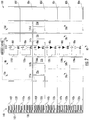
- FIG. 2 illustrates a schematic view of a building elevator system 100 incorporating the elevator system 10 of FIG. 1 , in accordance with an embodiment of the disclosure.
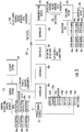
- FIG. 3 illustrates a block wiring diagram of the building elevator system 100 of FIG. 2 , in accordance with an embodiment of the disclosure.
- the elevator system 10 includes an elevator car 23 configured to move vertically upward and downward within a hoistway 50 along a plurality of car guide rails 60.
- the elevator car 23 includes a door 27 configured to open and close, allowing passengers (ex: occupants of the building) to enter and exit the elevator car 23.
- the elevator system 10 also includes a counterweight 28 operably connected to the elevator car 23 via a pulley system 26.
- the counterweight 28 is configured to move vertically upward and downward within the hoistway 50.
- the counterweight 28 moves in a direction generally opposite the movement of the elevator car 23, as is known in conventional elevator assemblies. Movement of the counterweight 28 is guided by counterweight guide rails 70 mounted within the hoistway 50.
- the elevator system 10 also includes a power source 12.
- the power is provided from the power source 12 to a switch panel 14, which may include circuit breakers, meters, etc. From the switch panel 14, the power may be provided directly to the drive unit 20 through the controller 30 or to an internal power source charger 16, which converts AC power to direct current (DC) power to charge an internal power source 18 that requires charging.
- an internal power source 18 that requires charging may be a battery, capacitor, or any other type of power storage device known to one of ordinary skill in the art.
- the internal power source 18 may not require charging from the external power source 12 and may be a device such as, for example a gas powered generator, solar cells, hydroelectric generator, wind turbine generator or similar power generation device.
- the internal power source 18 may power various components of the elevator system 10 when an external power source is unavailable.
- the drive unit 20 drives a machine 22 to impart motion to the elevator car 23 via a traction sheave of the machine 22.
- the machine 22 also includes a brake 24 that can be activated to stop the machine 22 and elevator car 23.
- FIG. 1 depicts a machine room-less elevator system 10, however the embodiments disclosed herein may be incorporated with other elevator systems that are not machine room-less or that include any other known elevator configuration.
- elevator systems having more than one independently operating elevator car in each elevator car shaft and/or ropeless elevator systems may also be used.
- the elevator car 23 may have two or more compartments.
- the controller 30 is responsible for controlling the operation of the elevator system 10.
- the controller 30 may also determine a mode (motoring, regenerative, near balance) of the elevator car 23.
- the controller 30 may use the car direction and the weight distribution between the elevator car 23 and the counterweight 28 to determine the mode of the elevator car 23.
- the controller 30 may adjust the velocity of the elevator car 23 to reach a target floor.
- the controller 30 may include a processor and an associated memory.
- the processor may be, but is not limited to, a single-processor or multi-processor system of any of a wide array of possible architectures, including field programmable gate array (FPGA), central processing unit (CPU), application specific integrated circuits (ASIC), digital signal processor (DSP) or graphics processing unit (GPU) hardware arranged homogenously or heterogeneously.
- the memory may be but is not limited to a random access memory (RAM), read only memory (ROM), or other electronic, optical, magnetic or any other computer readable medium.
- the elevator system 10 may also include a sensor system 141 configured to detect a remaining capacity in a particular elevator car 23.
- the remaining capacity allows the controller 30 to determine how much space is left in the elevator car 23. For instance, if the remaining capacity is equal to about zero there is no space left in the elevator car 23 to accept more passengers, whereas if the remaining capacity is greater than zero there may be space to accept more passengers in the elevator car 23.
- the sensor system 141 is in operative communication with the controller 30.
- the sensor system 141 may use a variety of sensing mechanisms such as, for example, a visual detection device, a weight detection device, a laser detection device, a door reversal monitoring device, a thermal image detection device, and a depth detection device.
- the visual detection device may be a camera that utilizes visual recognition to identify individual passengers and objects in the elevator car 23 and then determine remaining capacity.
- the weight detection device may be a scale to sense the amount of weight in an elevator car 23 and then determine the remaining capacity from the weight sensed.
- the laser detection device may detect how many passengers walk through a laser beam to determine the remaining capacity in the elevator car 23.
- a door reversal monitoring device also detects passengers entering the car so as not to close the elevator door on a passenger and thus may be used to determine the remaining capacity.
- the thermal detection device may be an infrared or other heat sensing camera that utilizes detected temperature to identify individual passengers and objects in the elevator car 23 and then determine remaining capacity.
- the depth detection device may be a 2-D, 3-D or other depth/distance detecting camera that utilizes detected distance to an object and/or passenger to determine remaining capacity.
- additional methods may exist to sense remaining capacity and one or any combination of these methods may be used to determine remaining capacity in the elevator car 23.
- FIG. 2 shows a building elevator system 100 incorporating a multiple elevator systems 10a-10d organized in an elevator bank 82 within a building 102.
- FIG. 2 only shows one elevator bank 82 for simplicity but more than one elevator banks may exist in the building 102.
- Each elevator system 10a-10d has an elevator car 23a-23d in an elevator hoistway 50a-50d.
- the building elevator system 100 is controlled by a system controller 110.
- the control system 110 is operably connected to the individual controller 30 (see FIG. 1 ) of each elevator system 10a-10d. In one embodiment, each elevator system 10a-10d may share a single controller 30.
- the control system 110 is configured to the control and coordinate operation of multiple elevator systems 10a-10d.
- the control system 110 may be an electronic controller including a processor and an associated memory comprising computer-executable instructions that, when executed by the processor, cause the processor to perform various operations.
- the processor may be, but is not limited to, a single-processor or multi-processor system of any of a wide array of possible architectures, including field programmable gate array (FPGA), central processing unit (CPU), application specific integrated circuits (ASIC), digital signal processor (DSP) or graphics processing unit (GPU) hardware arranged homogenously or heterogeneously.
- the memory may be but is not limited to a random access memory (RAM), read only memory (ROM), or other electronic, optical, magnetic or any other computer readable medium
- the building 102 includes multiple floors 80a-80f, each having an elevator call button 89a-89f and an evacuation alarm 88a-88f.
- the elevator call button 89a-89f sends an elevator call to the control system 110.
- the elevator call button 89a-89f may be a push button and/or a touch screen and may be activated manually or automatically.
- the elevator call button 89a-89f may be activated by a building occupant pushing the elevator call button 89a-89f.
- the elevator call button 89a-89f may also be activated voice recognition or a passenger detection mechanism in the hallway, such as, for example a weight sensing device, a visual recognition device, and a laser detection device.
- the evacuation alarm 88a-88f may be activated or deactivated either manually or automatically through a fire alarm system 180 ( FIG. 3 ). If the evacuation alarm 88a-88f is activated, an evacuation call is sent to the control system 110 indicating the respective floor 80a-80f where the evacuation alarm 88a-88f was activated. In the example of FIG. 2 , an evacuation alarm 88d is activated first on floor 80d and an evacuation alarm 88b is later activated on floor 80b. The evacuation alarm 88a, 88, 88e, 88f is not activated on floors 80a, 80c, 80e, and 80f. The first floor to activate an evacuation alarm may be known as the first evacuation floor. In the example of FIG. 2 , the first evacuation floor is floor 80d. The second evacuation floor to activate an evacuation alarm may be known as the second evacuation floor and so on.
- the first evacuation floor may be surrounded by padding floors, which are floors that are considered at increased risk due to their proximity to the evacuation floor and thus should also be evacuated.
- the padding floors for the first evacuation floor are floors 80b, 80c, 80e, and 80f.
- the padding floors may include floors that are a selected number of floors away from the first evacuation floor.
- the padding floors may include any number of floors on either side of an evacuation floor.
- the padding floors may include the floor immediately below the evacuation floor and the three floors immediately above the evacuation floor.
- the padding floors may include the two floors immediately below the evacuation floor and the two floors immediately above the evacuation floor.
- the first evacuation floor and the padding floors make up an evacuation zone.
- the evacuation zone is composed of floors 80b-80f.
- the floors 80b-80f that compose the evacuation zone may be determined automatically by the fire alarm system 180 or entered manually into the fire alarm system 180 through an interface device 190 (see FIG. 3 ).
- the interface device 190 may be at least one of an operational interface of the fire alarm system 180 and a user device.
- an operation interface is a device directly connected to the fire alarm system 180 within the building 102 where rescue personnel may input and receive information to and from the fire alarm system 180, such as, for example a fire control panel.
- a user device may be a mobile device, such as, for example a laptop, tablet, smart watch, or cellular phone. The rescue personnel may carry the user device with them and connect to the fire alarm system 180 through a wired and/or wireless connection.
- the evacuation priority of floors may be determined automatically by the fire alarm system 180 or by a manual input through the interface device 190. In an example, the evacuation priority may prioritize the first evacuation floor for evacuation, the evacuation zone for evacuation and/or higher floors for evacuation over lower floors.
- a second evacuation floor may also activate an evacuation alarm.
- the second evacuation floor is floor 80b.
- Evacuation floors may be evacuated in the order that the evacuation call is received. Padding floors of the first evacuation floor may be evacuated before the second evacuation floor. In one embodiment, all evacuation floors may be evacuated first, followed by padding floors associated with each evacuation floor in the order in which the corresponding evacuation call was placed.
- the second evacuation floor is contiguous to the padding floors of the first evacuation floor, the second evacuation floor and any subsequent evacuation floors may be located anywhere within the building.
- the building also includes a discharge floor, which is a floor where occupants can evacuate the building 102.
- the discharge floor may be a ground floor.
- the discharge floor is floor 80a.
- the building may also include a stairwell 130 as seen in FIG. 2 .
- the control system 110 may be configured to determine how many passengers are on a particular floor 80a-80f.
- the control system 110 may determine how many passengers are on a particular floor 80a-80f using an executable algorithm and/or a look up table that may be stored within the memory of the control system 110.
- the look up table may contain predicted number for how many passengers are on each floor 80a-80f on a particular date at a particular time. For example, the predicted number of passenger may be more for a day during the work week than a day on the weekend.
- the control system 110 may also determine how many passengers are on a particular floor 80a-80f using a building integrated personnel sensing system 140 composed a plurality of sensors throughout the building 102 configured to detect a number of passengers on each floor 80a-80f.
- the building integrated personnel sensing system 140 may count the number of passengers entering and exiting each floor 80a-80f using stairwell door sensors 142a-142f and also the sensor systems 141a-141d in each elevator car 23a-23d
- the stairwell door sensor 142a-142f counts the number of passengers entering and exiting the respective stairwell door 132a-132f.
- the stairwell door sensor 142a-142f may use a variety of sensing mechanisms such as, for example, a visual detection device, a weight detection device, a laser detection device, a thermal image detection device, and a depth detection device.
- the visual detection device may be a camera that utilizes visual recognition to identify and count individual passengers entering and exiting a particular floor 80a-80f from the stairwell 130.
- the weight detection device may be a scale to sense the amount of weight in an area proximate the stairwell door 132a-132f and then determine the number of passengers entering and exiting a particular floor 80a-80f from the weight sensed.
- the laser detection device may detect how many passengers walk through a laser beam located proximate the stairwell door 132a-132f to determine the number of passengers entering and exiting a floor 80a-80f.
- the thermal detection device may be an infrared or other heat sensing camera that utilizes detected temperature to identify how many passengers are located proximate the stairwell door 132a-132f to determine the number of passengers entering and exiting a floor 80a-80f.
- the depth detection device may be a 2-D, 3-D or other depth/distance detecting camera that utilizes detected distance to a passenger to determine how many passengers are located proximate the stairwell door 132a-132f to determine the number of passengers entering and exiting a floor 80a-80f.
- the stairwell door sensor 142a-142f interacts with the sensor systems 141a, 141b to determine the number of passengers on each floor 80a-80f.
- additional methods may exist to sense passengers and one or any combination of these methods may be used to determine the number of passengers entering and exiting a floor 80a-80f.
- the controller 30 could quickly identify how many passengers are on each floors 80a-80f and provide this information to rescue personnel via the interface device 190.
- each elevator bank 92, 94 includes a display 120a-120f on each floor 80a-80f.
- the displays 120a-120f may be a device for conveying information, such as, for example, a television screen or computer monitor.
- the displays 120a-120f are located proximate to the elevator systems 10a-10d on each floor 80a-80f.
- the control system 110 may determine the evacuation information to display on each display 120a-120f.
- the displays 120a-120f each display an estimated time of arrival of the elevator car 26 at the floor 80a-80f where the display 120a-120f is located.
- the estimated time of arrival may be determined by the control system 110 in response to at least one of an elevator car location within the building 102, an elevator car load weight status, an elevator car door state, an elevator car direction of travel, an elevator car speed, and an elevator destination floor.
- the elevator car load weight status is the weight that the elevator car 23a-23d is currently carrying, which may be determined by the sensor system 141a-141d, as discussed above.
- the elevator car door state is whether the door 27 is open or closed, which may also be determined by the sensor system 141a-141d or more specifically a door reversal device of the sensor system 141a-141d, as discussed above.
- the elevator destination floor is the floor 80a-80f where the display is located. In one example, if the display 120c is located on floor 80c then the destination floor is 80c and the display 120 will display the estimated time of arrival of the next elevator car 23a-23d to floor 80c.
- components of the building elevator system may be operably connected to each other through a campus area network (CAN) 200.
- the control system 110 is connected to and in operative communication with the fire alarm system 180.
- the fire alarm system 180 is connected to each fire alarm 88a-88f.
- the connection between the control system 110 and the fire alarm system 180 may be made through the CAN 200 and a communication bridge 170.
- the communication bridge 170 may use a communication protocol, such as, for example MODBUS, BACNet, and Metasys.
- the control system 110 may transmit to the fire alarm system 180 and the interface device 190 an elevator car status including at least one of an elevator car location within the building, an elevator car load weight status, an elevator car door state, an elevator car direction of travel, and an elevator car speed.
- the elevator car load weight status may be how much weight is currently in the elevator car 23.
- the elevator car door state may be whether or not the door 27 of the elevator car 23 is open or closed.
- the fire alarm system 180 may transmit to the control system 110 a fire alarm status including at least one of an active evacuation floor, a padding floor, a manual override, an evacuation zone evacuation command, and a total evacuation command.
- the fire alarm system 180 and/or rescue personnel may determine the active evacuation floor, the padding floor, an evacuation zone evacuation command, and a total evacuation command.
- the evacuation zone evacuation command would indicate to the control system 110 to first determine an evacuation zone including the evacuation floor and padding floors surrounding the evacuation zone, then evacuate the evacuation zone.
- the total evacuation command would be to evacuate the entire building from top to bottom.
- a manual override may be any manual command to control the elevator car 23 in a particular manor.
- controllers 30a-30d for each elevator car 23a-23d are connected to the CAN 200, as well as call buttons 89a-89f for each floor 80a-80f.
- a security system 160 may also be connected to the CAN 200.
- the displays 120a-120f for each floor 80a-80f are connected to the CAN 200.
- the displays 120a-120f may be connected through a bridge 13 or directly connected to the controllers 23a-23d.
- an abundance of information may be shared directly with rescue personnel who may subsequently use information, such as elevator estimated time of arrivals, to more efficiently carry out a building evacuation.
- FIG. 4 shows a flow chart of a method 400 of operating the building elevator system 100 of FIG. 2 , in accordance with an embodiment of the disclosure.
- the control system 110 controls the elevator system 10, which has an elevator car 23 as described above.
- the fire alarm system 180 detects a fire within the building 102.
- the fire alarm system 180 may include an interface device 190, as mentioned above.
- the control system 110 determines an estimated time of arrival of the elevator car 23 at a floor 80a-80f.
- the control system 110 transmits the estimated time of arrival to the fire alarm system 180.
- the control system 110 may also transmit the estimated time of arrival to the interface device 190.
- the method 400 may also include that the control system 110 transmits to the fire alarm system 180 an elevator car status including at least one of an elevator car location within the building, an elevator car load weight status, an elevator car door state, an elevator car direction of travel, and an elevator car speed.
- the method 400 may further include that the fire alarm system 180 transmits to the control system 110 a fire alarm status including at least one of an active evacuation floor, a padding floor, a manual override, an evacuation zone evacuation command, and a total evacuation command.
- the method 400 may still further include that the display 120a-120f displays the estimated time of arrival of the elevator car 23a-23d at the floor 80a-80f where the display 120a-120f is located. As mentioned above, the display 120a-120f is located on each floor 80a-80f proximate the elevator system 10a-10d and is in operative communication with the control system 110 and fire alarm system 180.
- embodiments can be in the form of processor-implemented processes and devices for practicing those processes, such as processor.
- Embodiments can also be in the form of computer program code containing instructions embodied in tangible media, such as network cloud storage, SD cards, flash drives, floppy diskettes, CD ROMs, hard drives, or any other computer-readable storage medium, wherein, when the computer program code is loaded into and executed by a computer, the computer becomes a device for practicing the embodiments.
- Embodiments can also be in the form of computer program code, for example, whether stored in a storage medium, loaded into and/or executed by a computer, or transmitted over some transmission medium, loaded into and/or executed by a computer, or transmitted over some transmission medium, such as over electrical wiring or cabling, through fiber optics, or via electromagnetic radiation, wherein, when the computer program code is loaded into an executed by a computer, the computer becomes an device for practicing the embodiments.
- the computer program code segments configure the microprocessor to create specific logic circuits.
Landscapes
- Engineering & Computer Science (AREA)
- Automation & Control Theory (AREA)
- Maintenance And Inspection Apparatuses For Elevators (AREA)
Claims (15)
- Gebäudeaufzugssystem (100), das Folgendes umfasst:ein Gebäude (102), das mehrere Stockwerke (80a-80f) aufweist;ein Aufzugssystem (10a-10d) innerhalb des Gebäudes, wobei das Aufzugssystem eine Aufzugskabine (26) aufweist;ein Steuerungssystem (110), das so konfiguriert ist, dass es das Aufzugssystem steuert, wobei das Steuersystem eine geschätzte Ankunftszeit der Aufzugskabine auf einem Stockwerk bestimmt; undein Feueralarmsystem (180) innerhalb des Gebäudes, das in operativer Kommunikation mit dem Steuerungssystem steht;dadurch gekennzeichnet, dassdas Steuerungssystem so konfiguriert ist, dass es die geschätzte Ankunftszeit der Aufzugskabine an das Feueralarmsystem übermittelt.
- Gebäudeaufzugssystem nach Anspruch 1, wobei:
das Feueralarmsystem ferner eine Schnittstellenvorrichtung (190) umfasst, wobei das Steuerungssystem so konfiguriert ist, dass es die geschätzte Ankunftszeit der Aufzugskabine an die Schnittstellenvorrichtung übermittelt. - Gebäudeaufzugssystem nach Anspruch 2, wobei:
die Schnittstellenvorrichtung mindestens eine einer operativen Schnittstelle des Feueralarmsystems und einer Benutzervorrichtung ist. - Gebäudeaufzugssystem nach Anspruch 2 oder 3, wobei:
das Steuerungssystem so konfiguriert ist, dass es einen Aufzugskabinenstatus an das Feueralarmsystem und die Schnittstellenvorrichtung übermittelt, der mindestens eines von einem Aufzugskabinenstandort innerhalb des Gebäudes, einem Aufzugskabinengewichtsbelastungsstatus, einem Aufzugskabinentürstatus, einer Aufzugskabinenfahrtrichtung und einer Aufzugskabinenfahrtgeschwindigkeit beinhaltet. - Gebäudeaufzugssystem nach einem der Ansprüche 1 bis 4, wobei:
das Feueralarmsystem so konfiguriert ist, dass es einen Feueralarmstatus an das Steuerungssystem übermittelt, der mindestens eines von einem aktiven Evakuierungsstockwerk, einem Polsterstockwerk, einer Handnotbetätigung, einem Evakuierungszonenevakuierungsbefehl und einem vollständigen Evakuierungsbefehl beinhaltet, wobei das Polsterstockwerk wegen seiner Nähe zu einem Evakuierungsstockwerk als Stockwerk mit erhöhtem Risiko erachtet wird. - Gebäudeaufzugssystem nach einem der Ansprüche 1 bis 5, wobei:
die geschätzte Ankunftszeit der Aufzugskabine als Reaktion auf mindestens eines von einem Aufzugskabinenstandort innerhalb des Gebäudes, einem Aufzugskabinengewichtsbelastungsstatus, einem Aufzugskabinentürstatus, einer Aufzugskabinenfahrtrichtung, eine Aufzugskabinenfahrtgeschwindigkeit oder einem Aufzugszielstockwerk bestimmt wird. - Gebäudeaufzugssystem nach einem der Ansprüche 1 bis 6, ferner umfassend:
eine Anzeige (120a-120f), die sich auf jedem Stockwerk in der Nähe des Aufzugssystems befindet und in operativer Kommunikation mit dem Steuerungssystem und Feueralarmsystem steht, wobei die Anzeige so konfiguriert ist, dass sie die geschätzte Ankunftszeit der Aufzugskabine auf dem Stockwerk, auf dem sich die Anzeige befindet, anzeigt. - Verfahren zum Betreiben eines Gebäudeaufzugssystems (100) für ein Gebäude (102), das mehrere Stockwerke (80a-80f) aufweist, wobei das Verfahren Folgendes umfasst:Steuern (404), unter Verwendung eines Steuerungssystems (110), eines Aufzugssystems (10a-10d), wobei das Aufzugssystem eine Aufzugskabine (26) aufweist;Erkennen (406), unter Verwendung eines Feueralarmsystems (180), eines Feuers innerhalb des Gebäudes;Bestimmen (408), unter Verwendung des Steuerungssystems, einer geschätzten Ankunftszeit der Aufzugskabine auf einem Stockwerk; undÜbertragen (410) der geschätzten Ankunftszeit des Feueralarmsystems, wobei das Steuerungssystem mit dem Feueralarmsystem in operativer Kommunikation steht.
- Verfahren nach Anspruch 8, wobei:
das Feueralarmsystem ferner eine Schnittstellenvorrichtung (190) umfasst, wobei das Steuerungssystem die geschätzte Ankunftszeit der Aufzugskabine an die Schnittstellenvorrichtung überträgt. - Verfahren nach Anspruch 9, wobei:
die Schnittstellenvorrichtung mindestens eine einer operativen Schnittstelle des Feueralarmsystems und einer Benutzervorrichtung ist. - Verfahren nach Anspruch 9 oder 10, ferner umfassend:
Übertragen, unter Verwendung des Steuerungssystems, eines Aufzugskabinenstatus, der mindestens eines von einem Aufzugskabinenstandort innerhalb des Gebäudes, einem Aufzugskabinengewichtsbelastungsstatus, einem Aufzugskabinentürstatus, einer Aufzugskabinenfahrtrichtung oder einer Aufzugskabinengeschwindigkeit beinhaltet, an das Feueralarmsystem und die Schnittstellenvorrichtung. - Verfahren nach einem der Ansprüche 8 bis 11, ferner umfassend:
Übertragen, unter Verwendung des Feueralarmsystems, einen Feueralarmstatus, der mindestens eines von einem aktiven Evakuierungsstockwerk, einem Polsterstockwerk, einer Handnotbetätigung, einen Evakuierungszonenevakuierungsbefehl und einem vollständigen Evakuierungsbefehl beinhaltet, an das Steuerungssystem, wobei das Polsterstockwerk wegen seiner Nähe zu einem Evakuierungsstockwerk als Stockwerk mit erhöhtem Risiko erachtet wird. - Verfahren nach einem der Ansprüche 8 bis 12, wobei:
die geschätzte Ankunftszeit der Aufzugskabine als Reaktion auf mindestens eines von einem Aufzugskabinenstandort innerhalb des Gebäudes, einem Aufzugskabinengewichtsbelastungsstatus, einem Aufzugskabinentürstatus, einer Aufzugskabinenfahrtrichtung, einer Aufzugskabinenfahrtgeschwindigkeit und einem Aufzugszielstockwerk bestimmt wird. - Verfahren nach einem der Ansprüche 8 bis 13, ferner umfassend:
Anzeigen, unter Verwendung einer Anzeige (120a-120f), der geschätzten Ankunftszeit der Aufzugskabine auf dem Stockwerk, auf dem sich die Anzeige befindet, wobei die Anzeige sich auf jedem Stockwerk in der Nähe des Aufzugssystems befindet und in operativer Kommunikation mit dem Steuerungssystem und Feueralarmsystem steht. - Computerprogrammprodukt, das greifbar in einem computerlesbaren Medium eingebettet ist, wobei das Computerprogrammprodukt Anweisungen beinhaltet, die, wenn sie von einem Prozessor des Steuerungssystems des Gebäudeaufzugssystems nach Anspruch 1 ausgeführt werden, den Prozessor dazu veranlassen, Vorgänge gemäß dem Verfahren nach einem der Ansprüche 8 bis 14 durchzuführen.
Applications Claiming Priority (1)
| Application Number | Priority Date | Filing Date | Title |
|---|---|---|---|
| US15/281,445 US20180093861A1 (en) | 2016-09-30 | 2016-09-30 | Enhanced elevator status information provisions for fire alarm systems |
Publications (2)
| Publication Number | Publication Date |
|---|---|
| EP3301056A1 EP3301056A1 (de) | 2018-04-04 |
| EP3301056B1 true EP3301056B1 (de) | 2020-03-25 |
Family
ID=59955423
Family Applications (1)
| Application Number | Title | Priority Date | Filing Date |
|---|---|---|---|
| EP17192580.3A Active EP3301056B1 (de) | 2016-09-30 | 2017-09-22 | Verbesserte aufzugsstatusinformationsbereitstellungen für feueralarmsysteme |
Country Status (3)
| Country | Link |
|---|---|
| US (1) | US20180093861A1 (de) |
| EP (1) | EP3301056B1 (de) |
| CN (1) | CN107879214A (de) |
Families Citing this family (6)
| Publication number | Priority date | Publication date | Assignee | Title |
|---|---|---|---|---|
| EP2984529B1 (de) * | 2013-04-12 | 2020-08-12 | KONE Corporation | Steuerungsvorrichtung für ein gebäudeautomatisierungssystem, verfahren und computerprogramm zur bereitstellung einer steuersignalisierung |
| US11370639B2 (en) * | 2017-09-20 | 2022-06-28 | Jessica Williams | Emergency elevator evacuation system |
| EP3613693B1 (de) | 2018-08-17 | 2022-10-05 | Otis Elevator Company | Aufzugssystem mit sensoren |
| EP4324779A3 (de) * | 2019-12-19 | 2024-03-27 | Otis Elevator Company | Selbstintelligente insassenevakuierungssysteme |
| CA3123976A1 (en) * | 2020-07-29 | 2022-01-29 | Appana Industries LLC | Systems and methods for parking elevators |
| EP4284741A1 (de) * | 2021-02-01 | 2023-12-06 | KONE Corporation | Aufzugskommunikationssystem, verfahren und vorrichtung |
Family Cites Families (9)
| Publication number | Priority date | Publication date | Assignee | Title |
|---|---|---|---|---|
| GB1502842A (en) * | 1974-04-22 | 1978-03-01 | Hitachi Ltd | Elevator control system |
| JP2004203623A (ja) * | 2002-12-23 | 2004-07-22 | Inventio Ag | 建物の人の緊急避難方法およびシステム、および前記システムを用いた既存の建物の近代化方法 |
| US7621378B2 (en) * | 2005-02-14 | 2009-11-24 | Mitsubishi Electric Corporation | System for controlled operation of elevator in case of fire and method of controlled operation of elevator in case of fire |
| CN101111441B (zh) * | 2006-01-20 | 2010-08-18 | 三菱电机株式会社 | 电梯控制系统 |
| JP5660594B2 (ja) * | 2009-12-15 | 2015-01-28 | 東芝エレベータ株式会社 | エレベータの運転制御装置 |
| JP5546852B2 (ja) * | 2009-12-22 | 2014-07-09 | 東芝エレベータ株式会社 | エレベータの救出運転システム |
| IT1402240B1 (it) * | 2010-07-21 | 2013-08-28 | Danieli Off Mecc | Apparecchiatura di mantenimento in temperatura e/o eventuale riscaldo di prodotti metallici lunghi e relativo procedimento |
| JP2012056696A (ja) * | 2010-09-08 | 2012-03-22 | Toshiba Elevator Co Ltd | エレベータシステム |
| EP3003945A4 (de) * | 2013-05-31 | 2017-03-15 | KONE Corporation | Evakuierungssystem für aufzug |
-
2016
- 2016-09-30 US US15/281,445 patent/US20180093861A1/en not_active Abandoned
-
2017
- 2017-09-22 EP EP17192580.3A patent/EP3301056B1/de active Active
- 2017-09-29 CN CN201710915193.7A patent/CN107879214A/zh active Pending
Non-Patent Citations (1)
| Title |
|---|
| None * |
Also Published As
| Publication number | Publication date |
|---|---|
| EP3301056A1 (de) | 2018-04-04 |
| US20180093861A1 (en) | 2018-04-05 |
| CN107879214A (zh) | 2018-04-06 |
Similar Documents
| Publication | Publication Date | Title |
|---|---|---|
| EP3301056B1 (de) | Verbesserte aufzugsstatusinformationsbereitstellungen für feueralarmsysteme | |
| EP3301055A2 (de) | Insassenevakuierungsvorgang durch zuweisung einer variablen anzahl von kabinen auf stockwerken innerhalb einer evakuierungszone | |
| EP3299324B1 (de) | Dynamische aufzugsanzeigen zur nachrichtenübermittlung und kommunikation | |
| US12497263B2 (en) | Elevator calling coordination for robots and individuals | |
| EP3301052B1 (de) | Gruppenkoordination von aufzügen innerhalb eines gebäudes zur insassenevakuierung | |
| EP3336031A1 (de) | Informationsvorschau für aufzuginsassen | |
| EP3305706A1 (de) | Insassenevakuierungsvorgangsanzeige | |
| EP3882199B1 (de) | Spezialisierter, personalisierter und verbesserter aufzugsruf für roboter und co-bots | |
| EP3309103A1 (de) | Verfahren für insassenevakuierungsvorgang mit aufzügen mit mehreren abteilen | |
| EP3301054B1 (de) | Optimierter insassenevakuierungsvorgang anhand der verbleibenden kapazität für aufzüge mit mehreren abteilen | |
| EP3301053B1 (de) | Erneute entsendung einer unbesetzten aufzugskabine für einen insassenevakuierungsvorgang | |
| EP3492416B1 (de) | Aufzugsgruppenmanagement zur insassenevakuierung | |
| EP3854740B1 (de) | Methode und system zur evakuierung der insassen | |
| US12503335B2 (en) | Control for shuttle elevator groups |
Legal Events
| Date | Code | Title | Description |
|---|---|---|---|
| PUAI | Public reference made under article 153(3) epc to a published international application that has entered the european phase |
Free format text: ORIGINAL CODE: 0009012 |
|
| STAA | Information on the status of an ep patent application or granted ep patent |
Free format text: STATUS: THE APPLICATION HAS BEEN PUBLISHED |
|
| AK | Designated contracting states |
Kind code of ref document: A1 Designated state(s): AL AT BE BG CH CY CZ DE DK EE ES FI FR GB GR HR HU IE IS IT LI LT LU LV MC MK MT NL NO PL PT RO RS SE SI SK SM TR |
|
| AX | Request for extension of the european patent |
Extension state: BA ME |
|
| STAA | Information on the status of an ep patent application or granted ep patent |
Free format text: STATUS: REQUEST FOR EXAMINATION WAS MADE |
|
| 17P | Request for examination filed |
Effective date: 20181004 |
|
| RBV | Designated contracting states (corrected) |
Designated state(s): AL AT BE BG CH CY CZ DE DK EE ES FI FR GB GR HR HU IE IS IT LI LT LU LV MC MK MT NL NO PL PT RO RS SE SI SK SM TR |
|
| GRAP | Despatch of communication of intention to grant a patent |
Free format text: ORIGINAL CODE: EPIDOSNIGR1 |
|
| STAA | Information on the status of an ep patent application or granted ep patent |
Free format text: STATUS: GRANT OF PATENT IS INTENDED |
|
| INTG | Intention to grant announced |
Effective date: 20191104 |
|
| GRAS | Grant fee paid |
Free format text: ORIGINAL CODE: EPIDOSNIGR3 |
|
| GRAA | (expected) grant |
Free format text: ORIGINAL CODE: 0009210 |
|
| STAA | Information on the status of an ep patent application or granted ep patent |
Free format text: STATUS: THE PATENT HAS BEEN GRANTED |
|
| AK | Designated contracting states |
Kind code of ref document: B1 Designated state(s): AL AT BE BG CH CY CZ DE DK EE ES FI FR GB GR HR HU IE IS IT LI LT LU LV MC MK MT NL NO PL PT RO RS SE SI SK SM TR |
|
| REG | Reference to a national code |
Ref country code: GB Ref legal event code: FG4D |
|
| REG | Reference to a national code |
Ref country code: AT Ref legal event code: REF Ref document number: 1248335 Country of ref document: AT Kind code of ref document: T Effective date: 20200415 Ref country code: IE Ref legal event code: FG4D |
|
| REG | Reference to a national code |
Ref country code: DE Ref legal event code: R096 Ref document number: 602017013526 Country of ref document: DE |
|
| PG25 | Lapsed in a contracting state [announced via postgrant information from national office to epo] |
Ref country code: FI Free format text: LAPSE BECAUSE OF FAILURE TO SUBMIT A TRANSLATION OF THE DESCRIPTION OR TO PAY THE FEE WITHIN THE PRESCRIBED TIME-LIMIT Effective date: 20200325 Ref country code: RS Free format text: LAPSE BECAUSE OF FAILURE TO SUBMIT A TRANSLATION OF THE DESCRIPTION OR TO PAY THE FEE WITHIN THE PRESCRIBED TIME-LIMIT Effective date: 20200325 Ref country code: NO Free format text: LAPSE BECAUSE OF FAILURE TO SUBMIT A TRANSLATION OF THE DESCRIPTION OR TO PAY THE FEE WITHIN THE PRESCRIBED TIME-LIMIT Effective date: 20200625 |
|
| PG25 | Lapsed in a contracting state [announced via postgrant information from national office to epo] |
Ref country code: BG Free format text: LAPSE BECAUSE OF FAILURE TO SUBMIT A TRANSLATION OF THE DESCRIPTION OR TO PAY THE FEE WITHIN THE PRESCRIBED TIME-LIMIT Effective date: 20200625 Ref country code: LV Free format text: LAPSE BECAUSE OF FAILURE TO SUBMIT A TRANSLATION OF THE DESCRIPTION OR TO PAY THE FEE WITHIN THE PRESCRIBED TIME-LIMIT Effective date: 20200325 Ref country code: SE Free format text: LAPSE BECAUSE OF FAILURE TO SUBMIT A TRANSLATION OF THE DESCRIPTION OR TO PAY THE FEE WITHIN THE PRESCRIBED TIME-LIMIT Effective date: 20200325 Ref country code: GR Free format text: LAPSE BECAUSE OF FAILURE TO SUBMIT A TRANSLATION OF THE DESCRIPTION OR TO PAY THE FEE WITHIN THE PRESCRIBED TIME-LIMIT Effective date: 20200626 Ref country code: HR Free format text: LAPSE BECAUSE OF FAILURE TO SUBMIT A TRANSLATION OF THE DESCRIPTION OR TO PAY THE FEE WITHIN THE PRESCRIBED TIME-LIMIT Effective date: 20200325 |
|
| REG | Reference to a national code |
Ref country code: NL Ref legal event code: MP Effective date: 20200325 |
|
| REG | Reference to a national code |
Ref country code: LT Ref legal event code: MG4D |
|
| PG25 | Lapsed in a contracting state [announced via postgrant information from national office to epo] |
Ref country code: NL Free format text: LAPSE BECAUSE OF FAILURE TO SUBMIT A TRANSLATION OF THE DESCRIPTION OR TO PAY THE FEE WITHIN THE PRESCRIBED TIME-LIMIT Effective date: 20200325 |
|
| PG25 | Lapsed in a contracting state [announced via postgrant information from national office to epo] |
Ref country code: PT Free format text: LAPSE BECAUSE OF FAILURE TO SUBMIT A TRANSLATION OF THE DESCRIPTION OR TO PAY THE FEE WITHIN THE PRESCRIBED TIME-LIMIT Effective date: 20200818 Ref country code: IS Free format text: LAPSE BECAUSE OF FAILURE TO SUBMIT A TRANSLATION OF THE DESCRIPTION OR TO PAY THE FEE WITHIN THE PRESCRIBED TIME-LIMIT Effective date: 20200725 Ref country code: SK Free format text: LAPSE BECAUSE OF FAILURE TO SUBMIT A TRANSLATION OF THE DESCRIPTION OR TO PAY THE FEE WITHIN THE PRESCRIBED TIME-LIMIT Effective date: 20200325 Ref country code: SM Free format text: LAPSE BECAUSE OF FAILURE TO SUBMIT A TRANSLATION OF THE DESCRIPTION OR TO PAY THE FEE WITHIN THE PRESCRIBED TIME-LIMIT Effective date: 20200325 Ref country code: EE Free format text: LAPSE BECAUSE OF FAILURE TO SUBMIT A TRANSLATION OF THE DESCRIPTION OR TO PAY THE FEE WITHIN THE PRESCRIBED TIME-LIMIT Effective date: 20200325 Ref country code: LT Free format text: LAPSE BECAUSE OF FAILURE TO SUBMIT A TRANSLATION OF THE DESCRIPTION OR TO PAY THE FEE WITHIN THE PRESCRIBED TIME-LIMIT Effective date: 20200325 Ref country code: RO Free format text: LAPSE BECAUSE OF FAILURE TO SUBMIT A TRANSLATION OF THE DESCRIPTION OR TO PAY THE FEE WITHIN THE PRESCRIBED TIME-LIMIT Effective date: 20200325 Ref country code: CZ Free format text: LAPSE BECAUSE OF FAILURE TO SUBMIT A TRANSLATION OF THE DESCRIPTION OR TO PAY THE FEE WITHIN THE PRESCRIBED TIME-LIMIT Effective date: 20200325 |
|
| REG | Reference to a national code |
Ref country code: AT Ref legal event code: MK05 Ref document number: 1248335 Country of ref document: AT Kind code of ref document: T Effective date: 20200325 |
|
| REG | Reference to a national code |
Ref country code: DE Ref legal event code: R097 Ref document number: 602017013526 Country of ref document: DE |
|
| PG25 | Lapsed in a contracting state [announced via postgrant information from national office to epo] |
Ref country code: IT Free format text: LAPSE BECAUSE OF FAILURE TO SUBMIT A TRANSLATION OF THE DESCRIPTION OR TO PAY THE FEE WITHIN THE PRESCRIBED TIME-LIMIT Effective date: 20200325 Ref country code: DK Free format text: LAPSE BECAUSE OF FAILURE TO SUBMIT A TRANSLATION OF THE DESCRIPTION OR TO PAY THE FEE WITHIN THE PRESCRIBED TIME-LIMIT Effective date: 20200325 Ref country code: AT Free format text: LAPSE BECAUSE OF FAILURE TO SUBMIT A TRANSLATION OF THE DESCRIPTION OR TO PAY THE FEE WITHIN THE PRESCRIBED TIME-LIMIT Effective date: 20200325 Ref country code: ES Free format text: LAPSE BECAUSE OF FAILURE TO SUBMIT A TRANSLATION OF THE DESCRIPTION OR TO PAY THE FEE WITHIN THE PRESCRIBED TIME-LIMIT Effective date: 20200325 |
|
| PLBE | No opposition filed within time limit |
Free format text: ORIGINAL CODE: 0009261 |
|
| STAA | Information on the status of an ep patent application or granted ep patent |
Free format text: STATUS: NO OPPOSITION FILED WITHIN TIME LIMIT |
|
| PG25 | Lapsed in a contracting state [announced via postgrant information from national office to epo] |
Ref country code: PL Free format text: LAPSE BECAUSE OF FAILURE TO SUBMIT A TRANSLATION OF THE DESCRIPTION OR TO PAY THE FEE WITHIN THE PRESCRIBED TIME-LIMIT Effective date: 20200325 |
|
| 26N | No opposition filed |
Effective date: 20210112 |
|
| REG | Reference to a national code |
Ref country code: DE Ref legal event code: R119 Ref document number: 602017013526 Country of ref document: DE |
|
| REG | Reference to a national code |
Ref country code: CH Ref legal event code: PL |
|
| PG25 | Lapsed in a contracting state [announced via postgrant information from national office to epo] |
Ref country code: SI Free format text: LAPSE BECAUSE OF FAILURE TO SUBMIT A TRANSLATION OF THE DESCRIPTION OR TO PAY THE FEE WITHIN THE PRESCRIBED TIME-LIMIT Effective date: 20200325 |
|
| REG | Reference to a national code |
Ref country code: BE Ref legal event code: MM Effective date: 20200930 |
|
| PG25 | Lapsed in a contracting state [announced via postgrant information from national office to epo] |
Ref country code: LU Free format text: LAPSE BECAUSE OF NON-PAYMENT OF DUE FEES Effective date: 20200922 |
|
| PG25 | Lapsed in a contracting state [announced via postgrant information from national office to epo] |
Ref country code: DE Free format text: LAPSE BECAUSE OF NON-PAYMENT OF DUE FEES Effective date: 20210401 Ref country code: FR Free format text: LAPSE BECAUSE OF NON-PAYMENT OF DUE FEES Effective date: 20200930 |
|
| PG25 | Lapsed in a contracting state [announced via postgrant information from national office to epo] |
Ref country code: CH Free format text: LAPSE BECAUSE OF NON-PAYMENT OF DUE FEES Effective date: 20200930 Ref country code: BE Free format text: LAPSE BECAUSE OF NON-PAYMENT OF DUE FEES Effective date: 20200930 Ref country code: LI Free format text: LAPSE BECAUSE OF NON-PAYMENT OF DUE FEES Effective date: 20200930 Ref country code: IE Free format text: LAPSE BECAUSE OF NON-PAYMENT OF DUE FEES Effective date: 20200922 |
|
| GBPC | Gb: european patent ceased through non-payment of renewal fee |
Effective date: 20210922 |
|
| PG25 | Lapsed in a contracting state [announced via postgrant information from national office to epo] |
Ref country code: TR Free format text: LAPSE BECAUSE OF FAILURE TO SUBMIT A TRANSLATION OF THE DESCRIPTION OR TO PAY THE FEE WITHIN THE PRESCRIBED TIME-LIMIT Effective date: 20200325 Ref country code: MT Free format text: LAPSE BECAUSE OF FAILURE TO SUBMIT A TRANSLATION OF THE DESCRIPTION OR TO PAY THE FEE WITHIN THE PRESCRIBED TIME-LIMIT Effective date: 20200325 Ref country code: CY Free format text: LAPSE BECAUSE OF FAILURE TO SUBMIT A TRANSLATION OF THE DESCRIPTION OR TO PAY THE FEE WITHIN THE PRESCRIBED TIME-LIMIT Effective date: 20200325 |
|
| PG25 | Lapsed in a contracting state [announced via postgrant information from national office to epo] |
Ref country code: MK Free format text: LAPSE BECAUSE OF FAILURE TO SUBMIT A TRANSLATION OF THE DESCRIPTION OR TO PAY THE FEE WITHIN THE PRESCRIBED TIME-LIMIT Effective date: 20200325 Ref country code: MC Free format text: LAPSE BECAUSE OF FAILURE TO SUBMIT A TRANSLATION OF THE DESCRIPTION OR TO PAY THE FEE WITHIN THE PRESCRIBED TIME-LIMIT Effective date: 20200325 Ref country code: AL Free format text: LAPSE BECAUSE OF FAILURE TO SUBMIT A TRANSLATION OF THE DESCRIPTION OR TO PAY THE FEE WITHIN THE PRESCRIBED TIME-LIMIT Effective date: 20200325 |
|
| PG25 | Lapsed in a contracting state [announced via postgrant information from national office to epo] |
Ref country code: GB Free format text: LAPSE BECAUSE OF NON-PAYMENT OF DUE FEES Effective date: 20210922 |