EP3301238A1 - Profil mit rückführung und federn, und entsprechende strebe - Google Patents
Profil mit rückführung und federn, und entsprechende strebe Download PDFInfo
- Publication number
- EP3301238A1 EP3301238A1 EP17182697.7A EP17182697A EP3301238A1 EP 3301238 A1 EP3301238 A1 EP 3301238A1 EP 17182697 A EP17182697 A EP 17182697A EP 3301238 A1 EP3301238 A1 EP 3301238A1
- Authority
- EP
- European Patent Office
- Prior art keywords
- profile
- spacer
- wing
- tongue
- wall structure
- Prior art date
- Legal status (The legal status is an assumption and is not a legal conclusion. Google has not performed a legal analysis and makes no representation as to the accuracy of the status listed.)
- Granted
Links
Images

Classifications
-
- E—FIXED CONSTRUCTIONS
- E04—BUILDING
- E04B—GENERAL BUILDING CONSTRUCTIONS; WALLS, e.g. PARTITIONS; ROOFS; FLOORS; CEILINGS; INSULATION OR OTHER PROTECTION OF BUILDINGS
- E04B9/00—Ceilings; Construction of ceilings, e.g. false ceilings; Ceiling construction with regard to insulation
- E04B9/06—Ceilings; Construction of ceilings, e.g. false ceilings; Ceiling construction with regard to insulation characterised by constructional features of the supporting construction, e.g. cross section or material of framework members
- E04B9/12—Connections between non-parallel members of the supporting construction
- E04B9/127—Connections between non-parallel members of the supporting construction one member being discontinuous and abutting against the other member
Definitions
- the present invention relates to a wall structure composed of a grid network.
- It relates more particularly to a profile for primary wall structure and a secondary framework spacer forming such a structure.
- the profiles of the primary framework are connected to a support, and the spacers of the secondary framework are mounted on the primary framework, usually orthogonally.
- the profiles used to produce the primary framework have a so-called "C” or "I” section. They most often have a bottom flange, that is to say a flat portion forming a support intended to extend in a plane parallel to that of the support, an upper flange, and a core (or middle part) connecting the lower sole to the upper sole and participating in the rigidity of the profile.
- the upper sole is traditionally connected to a hanger.
- the bottom flange is intended to be removed from the support in the mounted position while the upper flange is intended to be disposed on the support side in the mounted position.
- the spacers of the secondary frame are generally connected to the profiles of the primary frame by screws, or sometimes through a connecting device that can take the form of a loop or stirrup.
- the objective of the present invention is not only to simplify the implementation of a structure intended both for the production of false ceilings and bulkheads (any wall generally) and thus make it faster, but also to facilitate the production of profiles and spacers for forming this structure.
- the present invention also aims to simplify the implementation of the structure by reducing the number of elements necessary for the establishment and fixing of the spacers on the profiles and minimizing the risk of injury to a user.
- profile means a structure, a beam, primary frame, generally having a constant section, but where certain elements can be made punctually.
- the present invention also aims to provide a structure allowing ranges beyond three meters.
- the present invention also aims to allow a variable distribution of the spacers on the profiles.
- a profile for primary frame wall comprises a core, having at its base a lower flange forming a support, said flange comprising at least one wing forming an angle with the core, said flange having an end comprising a return, the core and the return extending from the same first face of the wing.
- the first face of the wing or the core comprises at least one tongue forming a stop in translation in a longitudinal direction (d) of the profile.
- wall a ceiling or a vertical partition such as a wall of a room.
- Such a profile generally of generally "I” shape, makes it possible to easily guide a spacer (for example in “U”), as defined later, when it is placed in position thanks to the wing return, and the tongue allows stop and hold the spacer in position.
- the cooperation between the tongue and the wing return allows a precise and easy positioning, of limit the translations, and retain a spacer during a vertical positioning of the profile.
- the profile generally has an "I" configuration.
- the return is orthogonal to the wing
- the soul is orthogonal to the sole.
- Such a tongue is formed of a blade attached on the one hand by a root, in this case to a surface formed by the first face of the flange of the sole or the core, and having a free end of other part, ie an opening.
- the tongue is also slightly elevated relative to the surface area to allow the spacer to be inserted.
- Such a tab is also occasionally called "latch" in the field considered.
- the profile comprises two tabs in opposite directions.
- Two tabs in opposite directions make the mechanical assembly more convenient and efficient.
- Two tabs in opposite directions also make it possible to overcome a predetermination of a direction of installation of the profile. This is particularly interesting when the profiles serve as a primary frame against a vertical wall, where the profiles are then preferably positioned so that an opening of the tongue is directed upward, ie its root down, so that a spacer can come to bear against the bottom of the tongue, ie against its root, by gravity.
- a profile as defined here has at least two tabs in opposite directions, there is thus always one of the two tongues in the direction for receiving a spacer abutting against its root if the profile is positioned on a vertical wall.
- the profile comprises several pairs of tongues in opposite directions.
- connection is understood to mean that two tabs are arranged in opposite directions back to back with a reduced space between them.
- Back-to-back means that the roots of the tongues of a pair are positioned side by side.
- a tongue has in front of it a space at least equal to a width of a spacer so that a spacer can be inserted.
- two consecutive tongues are in the same direction, it will be the space between the opening of a first tongue and the root of a second tongue.
- two successive tabs are in opposite directions, it will be the space between the opening of a first tab and the opening of a second tab. It is considered in this case that the first and the second tab are "face to face".
- the second tongue then belongs to another pair than that of the first tongue if the tongues are arranged in pairs.
- the core comprises at least one locking lug limiting displacement in a direction orthogonal to the wing.
- Such hearing provides stability to the spacer in a direction outside a plane defined by the profile flange, especially when screwing a plate.
- the tongue may have insufficient strength to avoid on its own lifting the spacer relative to the sole of the profile for example.
- the locking hole is equidistant from two tongues in opposite directions facing each other.
- the profile has for example at least one plane of symmetry, or two planes of symmetry, even three planes of symmetry which allows to install the profile in any sense.
- Is also proposed a spacer for secondary wall structure, comprising a lateral passage at one end configured to receive a locking tongue in translation relative to a profile and a cutout configured to cooperate with a wing return of a profile forming a translation guide means.
- the spacer has a generally "U" shape, with a bottom and two side flanks.
- two passages are formed on either side in the sidewalls for positioning the spacer independently of its direction and the positioning of the tabs of the profile.
- passage is meant here an opening, a lumen, formed laterally in the spacer, formed in a side of the spacer.
- the cutout extends from one side to the other and crosses the bottom of the spacer.
- the cutout extends for example all along a body of the spacer, but according to a particularly interesting example, the cutout has a slot shape, adapted to receive the wing return of the profile.
- flanks of the spacer have a flange, for example orthogonal to the sidewall, intended to bear against a locking hole formed in the core of a profile when the spacer is mounted on the profile.
- the spacer has a detent hump for cooperating with the blade of a tongue which then preferably has a corrugated shape to promote a locking of the spacer on the profile.
- the spacer has for example a plane of symmetry, or even two planes of symmetry, which facilitates the positioning of the spacer.
- the wall structure for example vertical, horizontal, inclined or stepped, comprises a grid network, the grid network being formed on the one hand of a primary framework of profiles as defined above, and on the other hand a secondary framework spacers as defined above, a spacer being positioned in abutment on a wing of a profile, and orthogonally to the profile, a tongue of the profile being inserted into a passage of the spacer, and a wing return of the profile being engaged in a cutout of the spacer.
- a flange of the spacer is in abutment against a locking hole formed in the core of the profile, for example to prevent the escape of the spacer when screwing the plate on said spacer.
- the wall structure comprises for example at least a first section and a second section connected by at least one splice.
- the splint comprises for example a core having an active surface from which extend an upper wing and a lower wing.
- the soul of the splint is in abutment against the core of at least the first profile, and for example the lower flange of the splint is in abutment against the lower sole of the splint.
- at least the first section and optionally the upper flange of the splint is in abutment against the upper flange of at least the first section if the at least first section further comprises an upper flange.
- at least one of the upper wing and the lower wing of the splice is positioned between the web of the at least first profile and at least one tongue formed on a first face of the wing of the at least first profile.
- a splice thus ensures continuity between two profiles.
- a splice is for example located on each side of the web of the profile if necessary to increase the rigidity and / or the robustness of the structure.
- the soul of the splint has at least one raised louver on its active surface to limit a displacement of a spacer in a direction orthogonal to the wing of one of the profiles.
- the splice has for example a cutout through which is positioned a hearing of a profile to provide this function of maintaining the spacer.
- Such splice has for example at least one plane of symmetry, and preferably two planes of symmetry to be easily and quickly inserted into the continuity of two consecutive profiles.
- two splints can, for example, be assembled to buttress two profiles at a different angle, such as for example a ceiling with redents.
- the web of the splice comprises, for example, a hole, allowing, for example, bolting, and is assembled back to back with a second splice connected to the second profile, the at least one splice and the second splice forming between them. an angle. The angle can be adjusted as needed when both profiles are butted.
- the laying of the spacers is thus simple and fast and can be done by a single user.
- the tabs allow instant attachment of the spacers with operating sets allowing great flexibility of implementation, as well as a simplified and quick installation.
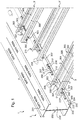
- a wall structure for example to make a false ceiling, comprises at least one assembly 1 between a profile 2 and a spacer 3.
- the section 2 is part of a primary frame of the structure. It comprises a core 200, having here an upper sole 201, and at its base a lower sole 202 forming a support.
- the lower sole 202 comprises at least one wing 203 forming an angle with the core 200.
- the lower sole 202 here has two wings symmetrical with respect to the core 200, located on either side of the core 200, which ensures a better stability and a better balance to the profile 2.
- Each wing 203 has an end including a return 204, here formed orthogonally to the wing 203.
- the core 200 and the return 204 extending from the same first face 209 of the wing 203.
- the return 204 further has a hem 205 to minimize the risk of injury to a user compared to a raw edge for example.
- Such a hem 205 also contributes to stiffening the section 2.
- the upper sole 201 has a structure identical to the lower sole 202, and they are preferably formed orthogonally to the core 200.
- the upper sole 201 could be devoid of return 204 for example.
- the profile 2 is here composed of two elements having generally a configuration in "C” placed back to back and connected by clinching or rivets for example (here by clinching).
- the profile thus has a generally "I” shape, which gives it for example a symmetry along a plane passing between the two "C”.
- C element is understood to mean that each element has at least one lower wing and one upper wing with their corresponding return, as well as a portion of the web of the profile forming the back of the "C".
- the lower wings form the lower sole 202 and the upper wings form the upper sole 201, and the backs of the "C” form the core 200 of the profile 2.
- the clinching allowing for example the assembly of the two elements, is preferably performed after folding elements "C" to not mechanically solicit the connection points.
- section 2 from a single sheet of steel (or other material) folded and folded on itself.
- a tongue 206, 206 ', 206 "capable of forming a translational stop is formed on the same first face 209 of the wing 203 as that mentioned above, at least on the bottom flange 202.
- the tongue 206, 206 ', 206 "thus forms a means for attaching a spacer 3 to the section 2.
- each wing of the profile 2 comprises at least one tongue 206, 206 ', 206 ".
- At least the wing 203 comprises several tabs 206, 206 ', 206 ", or all the wings of the section 2 comprise several tabs 206, 206', 206".
- a tab 206, 206 ', 206 "comes from the wing 203 of the section 2.
- a tongue 206, 206 ', 206 "comprises a blade 210, 210', waiting, and connected to the flange 203 by a root 207, 207 ', 207" on which is impaled laterally, until it comes into contact. stop, one end 301 of a spacer 3.
- a tab 206, 206 ', 206 " is a piece, in the form of a tab or a finger, made by cutting the wing 203 and by folding to form a zone, a blade, 210, 210 'generally parallel to the wing 203 on the side of the face 209 through a connecting zone to the wing 203, the root 207, 207', 207 ".
- the tabs 206, 206', 206" are for example all in the same direction, or some of the tabs may be in opposite directions , for example one tab out of two.
- Two tabs in opposite directions are for example represented by the tabs 206 and 206 ', or 206 and 206 ".
- two tabs 206 and 206 ' are positioned in bird's wings, ie back to back. They then form a double-tongue, a pair. A distance separating their respective roots 207 and 207 'is then for example reduced to a minimum.
- a tongue 206 is sufficiently far away from a tab 206 "which faces it so that a spacer can be inserted in.
- Two tabs facing each other are for example represented by the tongues 206 and 206" which are then not part of the same pair.
- Two consecutive tongues are for example spaced from each other by 100 mm, or 200 mm, for example, offering the possibility of varying the distribution of the spacers 3.
- the profile also comprises a locking lug 208.
- the locking lug 208 is for example formed in the core 200 of the section 2, for example by cutting and stamping. It is positioned so that it forms a support for a flange 305 of a spacer 3 so that the spacer 3 is prevented from moving away, lifting, from the flange 203 of the lower flange 202 on which it is climb.
- the locking hole 208 is preferably centered with respect to two tabs 206, 206" face to face.
- a spacer 3 can be locked on a tab 206 or a tab 206 "while having a flange 305 resting on the locking lug 208, thus avoiding an escape of the spacer 3 when screwing plates on the spacer3.
- a distance separating a root 207 from a tongue 206 from a root 207 "of a tongue 206" facing it is then for example approximately equal to twice a width (e) of a spacer 3.
- a spacer is brought into position as shown by the spacer 3 '. It is placed on the wing 203, and is translated, slid on one side or the other (left or right) as shown in the spacer 3 (which has been translated to the left) and the spacer 3 "(which has been translated to the right).
- the section 2 not only has locking holes 208 for a spacer 3 which would be positioned on a lower flange of the lower flange 202, but also the locking holes 208 '(in itself identical to a hearing 208) for a spacer which would be positioned on an upper wing of the upper sole 201.
- the indication 208 or 208 ' is here of course arbitrary and allows, in the context of this description, to be able to differentiate according to whether it refers to a lower part or upper profile.
- a locking groove 208 'oriented towards the upper sole 201 is particularly useful if the upper sole 201 comprises at least one tab 206,206', 206 ".
- two consecutive openings 208 are for example spaced 100 mm or 200 mm, or for example all the openings 208 of a section 2 are spaced from each other by the same distance.
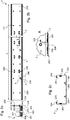
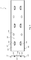
- the profile 2 thus has for example a plane of symmetry parallel to the axis (d) passing between the openings 208 and 208 ', and another plane of symmetry orthogonal to the axis (d), passing for example at middle of the profile according to its dimension along the axis (d).
- a profile 2 may have one, two or three planes of symmetry according to the embodiment envisaged.
- the presented embodiment Figures 2a to 2c presents three planes of symmetry, whereas that of the figure 1 present at least one or two.
- the spacer 3 has mainly a body 300 and a (generally two) end 301 mounting.
- the body 300 of the spacer 3 generally represents a portion of the spacer 3 situated between two sections 2.
- a spacer 3 has, for example, a length between two profiles 2 (that is to say a body length) allowing a distribution of these profiles 2 every 1.20 m or 1.50 m.
- the spacer 3 is here in a generally "U” configuration, a bottom 306 and two side flanks 304 each have a flange 305 formed here by an end of the flank 304 folded at right angles.
- the end 301 of the spacer 3 also has a cutout 303 here in the form of a slot, which can be made for example by notching.
- the cut 303 here extends from one flank 304 to the other and also passes through the bottom 306 so that the spacer 3 can bear against the return 204 of the flange 203 of the profile 2.
- the end 301 also here has a recess 307 which is particularly useful if the profile comprises a locking lug 208 (or 208 '), since it then allows it to be bypassed when the spacer 3 is put in position on the profile 2, as shown in the spacer in position 3 '.
- the notch 307 is for example made by notching.
- the end 301 further has a lateral passage 302, an opening in which is inserted a tongue.
- a passage 302 is also optionally made by notching.
- the end 301 comprises two passages 302 formed in each of the flanks 304 to allow attachment of the spacer 3 on a tongue on either side indifferently.
- the spacer 3 has for example a plane or two planes of symmetry.
- the spacer 3 then has at least one plane of symmetry, or preferably two planes of symmetry.
- the blade 210, 210 'of a tongue 206, 206', 206 "has a generally undulating form, in the form of wave, so as to be able to produce a detent, for example on a boss 308 formed on the bottom 306 of the spacer 3.
- a snap promotes a locking of the spacer 3 on the profile 2.
- the joint cooperations between the wing return 203 203 and the cutout 303, between a tongue 206, 206 ', 206 "and a passage 302, and between a flange 305 of a spacer flank 304 3 with a hearing locking members 208 allow a robust assembly minimizing relative movements between the spacer 3 and the profile 2, with easy assembly, fast, and secure.
- the locking hole 208 and the face 209 of the wing 203 have a distance equivalent to a height h of the spacer 3 so that it is locked in height once in position, ie in an orthogonal direction at the wing 203.
- the cooperation between the wing return 203 203 and the cut 303 allows blocking in a direction orthogonal to the core 200 and a translational guide along the wing 204 return 204 and the cooperation between a tab 206, 206 ', 206 "and its passage 302 allows precise positioning of the spacer 3 on the section 2 allowing the aforementioned blockages.
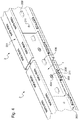
- a wall structure optionally comprises a splint 4 in the continuity between two profiles 2, for example if it is necessary to increase the range distance.
- the splint 4 comprises a core 400 having an active surface 403 from which extend an upper flange 401 and a lower flange 402.
- the upper wing 401 and the lower wing 402 are of identical sizes.
- the web 400 of the splint 4 thus bears against the web 200 of at least a first section 2, and the lower wing 402 of the splint 4 abuts against the lower flange 202 of at least the first profile 2 and the upper flange 401 of the splint 4 bears against the upper flange 201 of at least the first profile 2.
- the upper wing 401 and the lower wing 402 of the fishplate 4 are then each positioned between the web 200 of at least the first section 2 and at least one tongue 206, 206 ', 206 "formed on a first face 209 of a wing 203 of the lower sole 202 and the upper sole 201 of the section 2 (as is visible for example figure 4 ).
- the splint 4 is thus locked at the bottom of the profiles 2.
- the web 400 of the splice 4 furthermore has gills 408, 408 'in relief on the active surface 403 to limit a displacement of a spacer 3 in a direction orthogonal to the flange 203 of one of the profiles 2 when these are assembled.
- the core 400 of the splice 4 comprises for example passages 404, here oblong, to position for example vis-à-vis assembly points 211, for example clinching.
- one end of a section 2 is devoid of hearing 208, 208 'if gills 408,408' are present on the splice 4, and a back 405 of the core 400 of the splice 4 is possible devoid of any element in relief to promote surface-to-surface contact between the splice 4 and the profile 2, ie more precisely between the back 405 of the splice 4 and a surface 200 'of the core 200 of the profile 2.
- the splint 4 thus has two planes of symmetry.
- figure 5 presents another embodiment of a splint according to the invention.
- a splint 4 according to such an embodiment is for example intended for a section 2 whose upper flange 201 is devoid of pawls 206, 206 ', 206 "and gills 208' in the corresponding upper part of the core 200
- the splint 4 here has the core 400 having the active surface 403 from which the upper flange 401 and the lower flange 402 extend. figure 5 that the upper wing 401 is longer than the lower wing 402.
- the core 400 of the splint 4 as shown figure 5 is in abutment against the core 200 of the section 2 (whose upper flange 201 is devoid of pawl 206, 206 ', 206 ", and hearing 208' in the corresponding upper part of the core 200).
- 402 of the splice 4 is then in abutment against the lower sole 202 of the profile 2 between the core 200 of the profile 2 and at least one tongue 206, 206 ', 206 "formed on a first face 209 of the wing 203 of the bottom flange 202 of the profile 2.
- the upper flange 401 of the splint 4 is in abutment against the upper flange 201 of the profile 2, between the core 200 of the profile 2 and a return 204 of a flange 203 of the upper sole 201.
- a splint 4 thus makes it possible to ensure continuity between two profiles 2.
- a splice 4 is for example located on each side of the core 200 of the profile 2 if necessary to increase the rigidity and / or the robustness of the structure.
- the core 400 of the splice 4 has a cutout 406 through which is positioned an opening 208 of a profile 2 to provide this function of maintaining the spacer when the structure is assembled. It is then preventable that the section 2 is devoid of openings 208 towards its ends.
- such a fishplate 4 has a hole 407 (for example with a diameter of 6.2 mm), formed in the core 400 which is ready at one end, for example towards a middle of a height of the core 400, that is to say at equal distances from the upper wing 401 and the lower wing 402 for example.
- a hole 407 makes it possible, for example, to bolt back-to-back of two fishplates 4 in order to abut two sections 2, no longer in a linear fashion, but with an adjustable angle (eg attics, ceilings, etc.).
- Such a splint thus has a single plane of symmetry.
- the splice 4 has the choice of a lower flange 402 and / or an upper flange 401, the lower flange 402 and the upper flange 401 may be of identical or different sizes if
- the splint comprises both the lower flange 402 and the upper flange 401, optionally at least one lug 408 in the lower part, or optionally at least one louvre 408 'in the upper part, at least one cutout 406, and if required least one passage 404.
Landscapes
- Engineering & Computer Science (AREA)
- Architecture (AREA)
- Physics & Mathematics (AREA)
- Electromagnetism (AREA)
- Civil Engineering (AREA)
- Structural Engineering (AREA)
- Orthopedics, Nursing, And Contraception (AREA)
- Toys (AREA)
- Connection Of Plates (AREA)
- Joining Of Building Structures In Genera (AREA)
- Artificial Fish Reefs (AREA)
- Paper (AREA)
- Prostheses (AREA)
- Installation Of Indoor Wiring (AREA)
Applications Claiming Priority (3)
| Application Number | Priority Date | Filing Date | Title |
|---|---|---|---|
| FR1356402A FR3007777B1 (fr) | 2013-07-01 | 2013-07-01 | Profile a retour et languettes et entretoise associee |
| PCT/FR2014/051664 WO2015001237A2 (fr) | 2013-07-01 | 2014-06-30 | Profilé à retour et languettes et entretoise associée |
| EP14745192.6A EP3017121B1 (de) | 2013-07-01 | 2014-06-30 | Abschnitt mit lippe und zungen und zugehöriger abstandshalter |
Related Parent Applications (2)
| Application Number | Title | Priority Date | Filing Date |
|---|---|---|---|
| EP14745192.6A Division EP3017121B1 (de) | 2013-07-01 | 2014-06-30 | Abschnitt mit lippe und zungen und zugehöriger abstandshalter |
| EP14745192.6A Division-Into EP3017121B1 (de) | 2013-07-01 | 2014-06-30 | Abschnitt mit lippe und zungen und zugehöriger abstandshalter |
Publications (2)
| Publication Number | Publication Date |
|---|---|
| EP3301238A1 true EP3301238A1 (de) | 2018-04-04 |
| EP3301238B1 EP3301238B1 (de) | 2019-04-10 |
Family
ID=49378428
Family Applications (2)
| Application Number | Title | Priority Date | Filing Date |
|---|---|---|---|
| EP17182697.7A Active EP3301238B1 (de) | 2013-07-01 | 2014-06-30 | Profil mit rückführung und federn, und entsprechende strebe |
| EP14745192.6A Active EP3017121B1 (de) | 2013-07-01 | 2014-06-30 | Abschnitt mit lippe und zungen und zugehöriger abstandshalter |
Family Applications After (1)
| Application Number | Title | Priority Date | Filing Date |
|---|---|---|---|
| EP14745192.6A Active EP3017121B1 (de) | 2013-07-01 | 2014-06-30 | Abschnitt mit lippe und zungen und zugehöriger abstandshalter |
Country Status (6)
| Country | Link |
|---|---|
| EP (2) | EP3301238B1 (de) |
| ES (2) | ES2733919T3 (de) |
| FR (1) | FR3007777B1 (de) |
| PT (2) | PT3301238T (de) |
| TW (1) | TW201522751A (de) |
| WO (1) | WO2015001237A2 (de) |
Cited By (2)
| Publication number | Priority date | Publication date | Assignee | Title |
|---|---|---|---|---|
| GB2583362A (en) * | 2019-04-25 | 2020-10-28 | Quicktrak Ltd | Partition support structure mounting track |
| GB2597863A (en) * | 2019-04-25 | 2022-02-09 | Quicktrak Ltd | Partition support structure mounting track |
Families Citing this family (1)
| Publication number | Priority date | Publication date | Assignee | Title |
|---|---|---|---|---|
| FR3040063B1 (fr) | 2015-08-10 | 2018-10-12 | Ets Leroux S A | Profiles munis de moyens de liaison reciproque amovible |
Citations (9)
| Publication number | Priority date | Publication date | Assignee | Title |
|---|---|---|---|---|
| GB1417689A (en) * | 1973-05-23 | 1975-12-17 | Reininghaus A | Suspended ceiling structures |
| US3989399A (en) * | 1974-10-04 | 1976-11-02 | Slowbe Joseph A | Structural joint assembly |
| US4047348A (en) * | 1976-06-28 | 1977-09-13 | Johns-Manville Corporation | Ceiling support grid system |
| DE2641667A1 (de) * | 1976-09-16 | 1978-03-23 | Beck Stahlbau Fertigbau H | Profiltraeger zum herstellen einer deckenkonstruktion |
| US6729096B1 (en) * | 2002-09-09 | 2004-05-04 | Aaon Inc. | System for installing suspended ceiling |
| US20060010812A1 (en) * | 2004-07-14 | 2006-01-19 | Worthington Armstrong Venture | Molding for suspended panel ceiling |
| US20080229680A1 (en) * | 2007-03-21 | 2008-09-25 | Jahn Peter G | Wall angle with pre-punched locating tabs |
| US20080236068A1 (en) * | 2007-03-29 | 2008-10-02 | Jahn Peter G | Drywall channel with pre-punched locating tabs |
| FR2970012A1 (fr) | 2011-01-04 | 2012-07-06 | Placoplatre Sa | Profile pour ossature primaire de faux plafond |
Family Cites Families (1)
| Publication number | Priority date | Publication date | Assignee | Title |
|---|---|---|---|---|
| JP2000204711A (ja) * | 1999-01-12 | 2000-07-25 | Showa Alum Corp | 組立式冷蔵庫の天井補強梁 |
-
2013
- 2013-07-01 FR FR1356402A patent/FR3007777B1/fr not_active Expired - Fee Related
-
2014
- 2014-06-30 ES ES17182697T patent/ES2733919T3/es active Active
- 2014-06-30 ES ES14745192T patent/ES2935921T3/es active Active
- 2014-06-30 PT PT17182697T patent/PT3301238T/pt unknown
- 2014-06-30 PT PT147451926T patent/PT3017121T/pt unknown
- 2014-06-30 EP EP17182697.7A patent/EP3301238B1/de active Active
- 2014-06-30 TW TW103122610A patent/TW201522751A/zh unknown
- 2014-06-30 EP EP14745192.6A patent/EP3017121B1/de active Active
- 2014-06-30 WO PCT/FR2014/051664 patent/WO2015001237A2/fr not_active Ceased
Patent Citations (9)
| Publication number | Priority date | Publication date | Assignee | Title |
|---|---|---|---|---|
| GB1417689A (en) * | 1973-05-23 | 1975-12-17 | Reininghaus A | Suspended ceiling structures |
| US3989399A (en) * | 1974-10-04 | 1976-11-02 | Slowbe Joseph A | Structural joint assembly |
| US4047348A (en) * | 1976-06-28 | 1977-09-13 | Johns-Manville Corporation | Ceiling support grid system |
| DE2641667A1 (de) * | 1976-09-16 | 1978-03-23 | Beck Stahlbau Fertigbau H | Profiltraeger zum herstellen einer deckenkonstruktion |
| US6729096B1 (en) * | 2002-09-09 | 2004-05-04 | Aaon Inc. | System for installing suspended ceiling |
| US20060010812A1 (en) * | 2004-07-14 | 2006-01-19 | Worthington Armstrong Venture | Molding for suspended panel ceiling |
| US20080229680A1 (en) * | 2007-03-21 | 2008-09-25 | Jahn Peter G | Wall angle with pre-punched locating tabs |
| US20080236068A1 (en) * | 2007-03-29 | 2008-10-02 | Jahn Peter G | Drywall channel with pre-punched locating tabs |
| FR2970012A1 (fr) | 2011-01-04 | 2012-07-06 | Placoplatre Sa | Profile pour ossature primaire de faux plafond |
Cited By (5)
| Publication number | Priority date | Publication date | Assignee | Title |
|---|---|---|---|---|
| GB2583362A (en) * | 2019-04-25 | 2020-10-28 | Quicktrak Ltd | Partition support structure mounting track |
| GB2583362B (en) * | 2019-04-25 | 2021-12-08 | Quicktrak Ltd | Partition support structure mounting track |
| GB2597863A (en) * | 2019-04-25 | 2022-02-09 | Quicktrak Ltd | Partition support structure mounting track |
| GB2597863B (en) * | 2019-04-25 | 2022-06-01 | Quicktrak Ltd | Partition support structure mounting track |
| US12084857B2 (en) | 2019-04-25 | 2024-09-10 | Quicktrack Ltd. | Partition support structure mounting track |
Also Published As
| Publication number | Publication date |
|---|---|
| PT3017121T (pt) | 2023-01-27 |
| EP3301238B1 (de) | 2019-04-10 |
| FR3007777B1 (fr) | 2016-01-01 |
| FR3007777A1 (fr) | 2015-01-02 |
| ES2935921T3 (es) | 2023-03-13 |
| EP3017121A2 (de) | 2016-05-11 |
| PT3301238T (pt) | 2019-07-15 |
| WO2015001237A3 (fr) | 2015-03-05 |
| EP3017121B1 (de) | 2022-10-26 |
| WO2015001237A2 (fr) | 2015-01-08 |
| TW201522751A (zh) | 2015-06-16 |
| ES2733919T3 (es) | 2019-12-03 |
Similar Documents
| Publication | Publication Date | Title |
|---|---|---|
| FR2552474A1 (fr) | Grille pour plafond suspendu a face visible etroite | |
| EP3301238B1 (de) | Profil mit rückführung und federn, und entsprechende strebe | |
| EP2458103B1 (de) | Deckenplattensystem | |
| FR2900219A1 (fr) | Eclisse, procede d'assemblage d'ossature utilisant cette eclisse et ossature ainsi obtenue | |
| WO2000071820A1 (fr) | Glissiere de securite bois sur appuis a entraxes variables | |
| FR3083291A1 (fr) | Systeme de connexion pour elements de forme allongee | |
| FR3037348A1 (fr) | Eclisse d'assemblage | |
| EP0421905A1 (de) | Regalvorrichtung | |
| EP1471207B1 (de) | Befestigungssystem für Lamellen und Aussenwand mit einem solchen System | |
| FR3025503A1 (fr) | Ensemble de construction pour pylone d’ascenseur et pylone d’ascenseur associe | |
| EP1617155B1 (de) | Lüftungsgitter | |
| EP2453540B1 (de) | Universalhalterungssschiene | |
| EP3748097B1 (de) | Metallrahmen für vorgefertigte trockenbau-platten | |
| FR3057886A1 (fr) | Systeme de parement, ensemble de parement d'au moins deux systemes de parement superposes, et cloison, parement et cloture comprenant au moins un ensemble de parement | |
| EP1722111A1 (de) | Befestigungselement zur Befestigung eines Metallprofils auf einem Träger | |
| FR2970017A1 (fr) | Dispositif pour l'assemblage d'une marche sur un support | |
| EP3372752B1 (de) | Verankerungsanordnung zur verankerung durch eine öffnung eines vorgeschnittenen trockenwandteils | |
| EP2264255B1 (de) | Trennwandstruktur, insbesondere einer Hohltrennwand | |
| FR2757696A1 (fr) | Console pour conduits porteurs | |
| EP2182127A1 (de) | Struktur mit einer ersten und einer zweiten Wand, im wesentlichen wagerecht und voneinander beabstandet | |
| EP3162973B1 (de) | Anschlussvorrichtung für eine decke, die an einer bodenplatte abgehängt ist | |
| EP4613949A1 (de) | Platte für abgehängte decke, abgehängtes deckensystem und plattenkit | |
| EP3916168A1 (de) | Abstandhalter für die auskleidung einer wand | |
| FR2657379A1 (fr) | Patte pour la mise en place d'une entretoise entre deux profiles. | |
| WO2014053441A1 (fr) | Suspente fine pour fourrures de construction |
Legal Events
| Date | Code | Title | Description |
|---|---|---|---|
| PUAI | Public reference made under article 153(3) epc to a published international application that has entered the european phase |
Free format text: ORIGINAL CODE: 0009012 |
|
| STAA | Information on the status of an ep patent application or granted ep patent |
Free format text: STATUS: THE APPLICATION HAS BEEN PUBLISHED |
|
| AC | Divisional application: reference to earlier application |
Ref document number: 3017121 Country of ref document: EP Kind code of ref document: P |
|
| AK | Designated contracting states |
Kind code of ref document: A1 Designated state(s): AL AT BE BG CH CY CZ DE DK EE ES FI FR GB GR HR HU IE IS IT LI LT LU LV MC MK MT NL NO PL PT RO RS SE SI SK SM TR |
|
| STAA | Information on the status of an ep patent application or granted ep patent |
Free format text: STATUS: REQUEST FOR EXAMINATION WAS MADE |
|
| 17P | Request for examination filed |
Effective date: 20180412 |
|
| RBV | Designated contracting states (corrected) |
Designated state(s): AL AT BE BG CH CY CZ DE DK EE ES FI FR GB GR HR HU IE IS IT LI LT LU LV MC MK MT NL NO PL PT RO RS SE SI SK SM TR |
|
| GRAP | Despatch of communication of intention to grant a patent |
Free format text: ORIGINAL CODE: EPIDOSNIGR1 |
|
| STAA | Information on the status of an ep patent application or granted ep patent |
Free format text: STATUS: GRANT OF PATENT IS INTENDED |
|
| INTG | Intention to grant announced |
Effective date: 20181205 |
|
| GRAS | Grant fee paid |
Free format text: ORIGINAL CODE: EPIDOSNIGR3 |
|
| GRAJ | Information related to disapproval of communication of intention to grant by the applicant or resumption of examination proceedings by the epo deleted |
Free format text: ORIGINAL CODE: EPIDOSDIGR1 |
|
| GRAL | Information related to payment of fee for publishing/printing deleted |
Free format text: ORIGINAL CODE: EPIDOSDIGR3 |
|
| STAA | Information on the status of an ep patent application or granted ep patent |
Free format text: STATUS: REQUEST FOR EXAMINATION WAS MADE |
|
| GRAR | Information related to intention to grant a patent recorded |
Free format text: ORIGINAL CODE: EPIDOSNIGR71 |
|
| STAA | Information on the status of an ep patent application or granted ep patent |
Free format text: STATUS: GRANT OF PATENT IS INTENDED |
|
| GRAA | (expected) grant |
Free format text: ORIGINAL CODE: 0009210 |
|
| STAA | Information on the status of an ep patent application or granted ep patent |
Free format text: STATUS: THE PATENT HAS BEEN GRANTED |
|
| INTC | Intention to grant announced (deleted) | ||
| INTG | Intention to grant announced |
Effective date: 20190228 |
|
| AC | Divisional application: reference to earlier application |
Ref document number: 3017121 Country of ref document: EP Kind code of ref document: P |
|
| AK | Designated contracting states |
Kind code of ref document: B1 Designated state(s): AL AT BE BG CH CY CZ DE DK EE ES FI FR GB GR HR HU IE IS IT LI LT LU LV MC MK MT NL NO PL PT RO RS SE SI SK SM TR |
|
| REG | Reference to a national code |
Ref country code: GB Ref legal event code: FG4D Free format text: NOT ENGLISH |
|
| REG | Reference to a national code |
Ref country code: CH Ref legal event code: EP Ref country code: AT Ref legal event code: REF Ref document number: 1118824 Country of ref document: AT Kind code of ref document: T Effective date: 20190415 |
|
| REG | Reference to a national code |
Ref country code: IE Ref legal event code: FG4D Free format text: LANGUAGE OF EP DOCUMENT: FRENCH |
|
| REG | Reference to a national code |
Ref country code: DE Ref legal event code: R096 Ref document number: 602014044741 Country of ref document: DE |
|
| REG | Reference to a national code |
Ref country code: PT Ref legal event code: SC4A Ref document number: 3301238 Country of ref document: PT Date of ref document: 20190715 Kind code of ref document: T Free format text: AVAILABILITY OF NATIONAL TRANSLATION Effective date: 20190704 |
|
| REG | Reference to a national code |
Ref country code: NL Ref legal event code: MP Effective date: 20190410 |
|
| REG | Reference to a national code |
Ref country code: LT Ref legal event code: MG4D |
|
| REG | Reference to a national code |
Ref country code: AT Ref legal event code: MK05 Ref document number: 1118824 Country of ref document: AT Kind code of ref document: T Effective date: 20190410 |
|
| PG25 | Lapsed in a contracting state [announced via postgrant information from national office to epo] |
Ref country code: NL Free format text: LAPSE BECAUSE OF FAILURE TO SUBMIT A TRANSLATION OF THE DESCRIPTION OR TO PAY THE FEE WITHIN THE PRESCRIBED TIME-LIMIT Effective date: 20190410 |
|
| PG25 | Lapsed in a contracting state [announced via postgrant information from national office to epo] |
Ref country code: SE Free format text: LAPSE BECAUSE OF FAILURE TO SUBMIT A TRANSLATION OF THE DESCRIPTION OR TO PAY THE FEE WITHIN THE PRESCRIBED TIME-LIMIT Effective date: 20190410 Ref country code: HR Free format text: LAPSE BECAUSE OF FAILURE TO SUBMIT A TRANSLATION OF THE DESCRIPTION OR TO PAY THE FEE WITHIN THE PRESCRIBED TIME-LIMIT Effective date: 20190410 Ref country code: AL Free format text: LAPSE BECAUSE OF FAILURE TO SUBMIT A TRANSLATION OF THE DESCRIPTION OR TO PAY THE FEE WITHIN THE PRESCRIBED TIME-LIMIT Effective date: 20190410 Ref country code: FI Free format text: LAPSE BECAUSE OF FAILURE TO SUBMIT A TRANSLATION OF THE DESCRIPTION OR TO PAY THE FEE WITHIN THE PRESCRIBED TIME-LIMIT Effective date: 20190410 Ref country code: NO Free format text: LAPSE BECAUSE OF FAILURE TO SUBMIT A TRANSLATION OF THE DESCRIPTION OR TO PAY THE FEE WITHIN THE PRESCRIBED TIME-LIMIT Effective date: 20190710 Ref country code: LT Free format text: LAPSE BECAUSE OF FAILURE TO SUBMIT A TRANSLATION OF THE DESCRIPTION OR TO PAY THE FEE WITHIN THE PRESCRIBED TIME-LIMIT Effective date: 20190410 |
|
| PG25 | Lapsed in a contracting state [announced via postgrant information from national office to epo] |
Ref country code: GR Free format text: LAPSE BECAUSE OF FAILURE TO SUBMIT A TRANSLATION OF THE DESCRIPTION OR TO PAY THE FEE WITHIN THE PRESCRIBED TIME-LIMIT Effective date: 20190711 Ref country code: BG Free format text: LAPSE BECAUSE OF FAILURE TO SUBMIT A TRANSLATION OF THE DESCRIPTION OR TO PAY THE FEE WITHIN THE PRESCRIBED TIME-LIMIT Effective date: 20190710 Ref country code: RS Free format text: LAPSE BECAUSE OF FAILURE TO SUBMIT A TRANSLATION OF THE DESCRIPTION OR TO PAY THE FEE WITHIN THE PRESCRIBED TIME-LIMIT Effective date: 20190410 Ref country code: LV Free format text: LAPSE BECAUSE OF FAILURE TO SUBMIT A TRANSLATION OF THE DESCRIPTION OR TO PAY THE FEE WITHIN THE PRESCRIBED TIME-LIMIT Effective date: 20190410 Ref country code: PL Free format text: LAPSE BECAUSE OF FAILURE TO SUBMIT A TRANSLATION OF THE DESCRIPTION OR TO PAY THE FEE WITHIN THE PRESCRIBED TIME-LIMIT Effective date: 20190410 |
|
| REG | Reference to a national code |
Ref country code: ES Ref legal event code: FG2A Ref document number: 2733919 Country of ref document: ES Kind code of ref document: T3 Effective date: 20191203 |
|
| PG25 | Lapsed in a contracting state [announced via postgrant information from national office to epo] |
Ref country code: AT Free format text: LAPSE BECAUSE OF FAILURE TO SUBMIT A TRANSLATION OF THE DESCRIPTION OR TO PAY THE FEE WITHIN THE PRESCRIBED TIME-LIMIT Effective date: 20190410 Ref country code: IS Free format text: LAPSE BECAUSE OF FAILURE TO SUBMIT A TRANSLATION OF THE DESCRIPTION OR TO PAY THE FEE WITHIN THE PRESCRIBED TIME-LIMIT Effective date: 20190810 |
|
| REG | Reference to a national code |
Ref country code: DE Ref legal event code: R097 Ref document number: 602014044741 Country of ref document: DE |
|
| PG25 | Lapsed in a contracting state [announced via postgrant information from national office to epo] |
Ref country code: EE Free format text: LAPSE BECAUSE OF FAILURE TO SUBMIT A TRANSLATION OF THE DESCRIPTION OR TO PAY THE FEE WITHIN THE PRESCRIBED TIME-LIMIT Effective date: 20190410 Ref country code: DK Free format text: LAPSE BECAUSE OF FAILURE TO SUBMIT A TRANSLATION OF THE DESCRIPTION OR TO PAY THE FEE WITHIN THE PRESCRIBED TIME-LIMIT Effective date: 20190410 Ref country code: CZ Free format text: LAPSE BECAUSE OF FAILURE TO SUBMIT A TRANSLATION OF THE DESCRIPTION OR TO PAY THE FEE WITHIN THE PRESCRIBED TIME-LIMIT Effective date: 20190410 Ref country code: RO Free format text: LAPSE BECAUSE OF FAILURE TO SUBMIT A TRANSLATION OF THE DESCRIPTION OR TO PAY THE FEE WITHIN THE PRESCRIBED TIME-LIMIT Effective date: 20190410 Ref country code: SK Free format text: LAPSE BECAUSE OF FAILURE TO SUBMIT A TRANSLATION OF THE DESCRIPTION OR TO PAY THE FEE WITHIN THE PRESCRIBED TIME-LIMIT Effective date: 20190410 Ref country code: MC Free format text: LAPSE BECAUSE OF FAILURE TO SUBMIT A TRANSLATION OF THE DESCRIPTION OR TO PAY THE FEE WITHIN THE PRESCRIBED TIME-LIMIT Effective date: 20190410 |
|
| REG | Reference to a national code |
Ref country code: CH Ref legal event code: PL |
|
| PLBE | No opposition filed within time limit |
Free format text: ORIGINAL CODE: 0009261 |
|
| STAA | Information on the status of an ep patent application or granted ep patent |
Free format text: STATUS: NO OPPOSITION FILED WITHIN TIME LIMIT |
|
| PG25 | Lapsed in a contracting state [announced via postgrant information from national office to epo] |
Ref country code: SM Free format text: LAPSE BECAUSE OF FAILURE TO SUBMIT A TRANSLATION OF THE DESCRIPTION OR TO PAY THE FEE WITHIN THE PRESCRIBED TIME-LIMIT Effective date: 20190410 Ref country code: IT Free format text: LAPSE BECAUSE OF FAILURE TO SUBMIT A TRANSLATION OF THE DESCRIPTION OR TO PAY THE FEE WITHIN THE PRESCRIBED TIME-LIMIT Effective date: 20190410 |
|
| 26N | No opposition filed |
Effective date: 20200113 |
|
| REG | Reference to a national code |
Ref country code: BE Ref legal event code: MM Effective date: 20190630 |
|
| PG25 | Lapsed in a contracting state [announced via postgrant information from national office to epo] |
Ref country code: TR Free format text: LAPSE BECAUSE OF FAILURE TO SUBMIT A TRANSLATION OF THE DESCRIPTION OR TO PAY THE FEE WITHIN THE PRESCRIBED TIME-LIMIT Effective date: 20190410 |
|
| PG25 | Lapsed in a contracting state [announced via postgrant information from national office to epo] |
Ref country code: IE Free format text: LAPSE BECAUSE OF NON-PAYMENT OF DUE FEES Effective date: 20190630 |
|
| PG25 | Lapsed in a contracting state [announced via postgrant information from national office to epo] |
Ref country code: LU Free format text: LAPSE BECAUSE OF NON-PAYMENT OF DUE FEES Effective date: 20190630 Ref country code: CH Free format text: LAPSE BECAUSE OF NON-PAYMENT OF DUE FEES Effective date: 20190630 Ref country code: LI Free format text: LAPSE BECAUSE OF NON-PAYMENT OF DUE FEES Effective date: 20190630 Ref country code: SI Free format text: LAPSE BECAUSE OF FAILURE TO SUBMIT A TRANSLATION OF THE DESCRIPTION OR TO PAY THE FEE WITHIN THE PRESCRIBED TIME-LIMIT Effective date: 20190410 Ref country code: BE Free format text: LAPSE BECAUSE OF NON-PAYMENT OF DUE FEES Effective date: 20190630 |
|
| PG25 | Lapsed in a contracting state [announced via postgrant information from national office to epo] |
Ref country code: CY Free format text: LAPSE BECAUSE OF FAILURE TO SUBMIT A TRANSLATION OF THE DESCRIPTION OR TO PAY THE FEE WITHIN THE PRESCRIBED TIME-LIMIT Effective date: 20190410 |
|
| PG25 | Lapsed in a contracting state [announced via postgrant information from national office to epo] |
Ref country code: HU Free format text: LAPSE BECAUSE OF FAILURE TO SUBMIT A TRANSLATION OF THE DESCRIPTION OR TO PAY THE FEE WITHIN THE PRESCRIBED TIME-LIMIT; INVALID AB INITIO Effective date: 20140630 Ref country code: MT Free format text: LAPSE BECAUSE OF FAILURE TO SUBMIT A TRANSLATION OF THE DESCRIPTION OR TO PAY THE FEE WITHIN THE PRESCRIBED TIME-LIMIT Effective date: 20190410 |
|
| PG25 | Lapsed in a contracting state [announced via postgrant information from national office to epo] |
Ref country code: MK Free format text: LAPSE BECAUSE OF FAILURE TO SUBMIT A TRANSLATION OF THE DESCRIPTION OR TO PAY THE FEE WITHIN THE PRESCRIBED TIME-LIMIT Effective date: 20190410 |
|
| PGFP | Annual fee paid to national office [announced via postgrant information from national office to epo] |
Ref country code: DE Payment date: 20250507 Year of fee payment: 12 |
|
| PGFP | Annual fee paid to national office [announced via postgrant information from national office to epo] |
Ref country code: GB Payment date: 20250508 Year of fee payment: 12 |
|
| PGFP | Annual fee paid to national office [announced via postgrant information from national office to epo] |
Ref country code: PT Payment date: 20250612 Year of fee payment: 12 |
|
| PGFP | Annual fee paid to national office [announced via postgrant information from national office to epo] |
Ref country code: FR Payment date: 20250508 Year of fee payment: 12 |
|
| PGFP | Annual fee paid to national office [announced via postgrant information from national office to epo] |
Ref country code: ES Payment date: 20250707 Year of fee payment: 12 |