EP3301246A1 - Dispositif pour bloquer l'ouverture d'un verrou de porte de l'intérieur - Google Patents
Dispositif pour bloquer l'ouverture d'un verrou de porte de l'intérieur Download PDFInfo
- Publication number
- EP3301246A1 EP3301246A1 EP17194200.6A EP17194200A EP3301246A1 EP 3301246 A1 EP3301246 A1 EP 3301246A1 EP 17194200 A EP17194200 A EP 17194200A EP 3301246 A1 EP3301246 A1 EP 3301246A1
- Authority
- EP
- European Patent Office
- Prior art keywords
- bolt
- latch
- vertical
- housing
- width
- Prior art date
- Legal status (The legal status is an assumption and is not a legal conclusion. Google has not performed a legal analysis and makes no representation as to the accuracy of the status listed.)
- Granted
Links
- 230000000903 blocking effect Effects 0.000 title claims description 5
- 239000007787 solid Substances 0.000 claims abstract description 6
- 238000010586 diagram Methods 0.000 description 2
- 210000000078 claw Anatomy 0.000 description 1
- 230000000284 resting effect Effects 0.000 description 1
Images

Classifications
-
- E—FIXED CONSTRUCTIONS
- E05—LOCKS; KEYS; WINDOW OR DOOR FITTINGS; SAFES
- E05B—LOCKS; ACCESSORIES THEREFOR; HANDCUFFS
- E05B17/00—Accessories in connection with locks
- E05B17/20—Means independent of the locking mechanism for preventing unauthorised opening, e.g. for securing the bolt in the fastening position
- E05B17/2007—Securing, deadlocking or "dogging" the bolt in the fastening position
- E05B17/2023—Loose pins, screws, or the like; Portable devices
-
- E—FIXED CONSTRUCTIONS
- E05—LOCKS; KEYS; WINDOW OR DOOR FITTINGS; SAFES
- E05C—BOLTS OR FASTENING DEVICES FOR WINGS, SPECIALLY FOR DOORS OR WINDOWS
- E05C19/00—Other devices specially designed for securing wings, e.g. with suction cups
- E05C19/18—Portable devices specially adapted for securing wings
- E05C19/188—Removably mounted securing devices, e.g. devices clamped to the wing or the frame
-
- E—FIXED CONSTRUCTIONS
- E05—LOCKS; KEYS; WINDOW OR DOOR FITTINGS; SAFES
- E05C—BOLTS OR FASTENING DEVICES FOR WINGS, SPECIALLY FOR DOORS OR WINDOWS
- E05C19/00—Other devices specially designed for securing wings, e.g. with suction cups
- E05C19/18—Portable devices specially adapted for securing wings
Definitions
- the present invention relates to a device for blocking the opening of a door lock from the inside.
- the lock opening is possible from outside a house even without having keys. We can then, from the outside, turn the lock and back the bolt thereof with a key or other device.
- the document FR539759 discloses a safety device applicable to safety locks to prohibit any action from outside on these locks, which device is essentially constituted by a kind of claw for pressing the latch button.
- the device described in the document FR539759 can only be used with latches that have a latch knob.
- the present invention aims to solve this drawback of the prior art, by providing a device adapted to adapt to all types of lock including a bolt not included in the door frame.
- the present invention therefore relates to a device for blocking the sliding of a bolt during an attempt to open unwanted latch, which latch comprises a box, a latch and said bolt having a head adapted to engage in the strike in the closed position lock and a heel opposite the head, characterized in that it comprises a housing having the shape of a "U" upside down, and thus having a horizontal upper portion and two vertical side portions, a vertical portion of which rear consisting of a solid arm adapted to be placed behind the heel of the bolt, and a vertical front part consisting of two arms separated by a space and able to be between the trunk and latch strike in the closed position of the latter, so as to maintain the housing, allowing the bolt to pass through the space between the two arms, the upper horizontal part resting on the trunk and the full arm preventing the sliding of the bolt in the opening direction of the lock.
- the rear vertical portion of the housing has a cross-sectional section C, having a central section extending facing the front vertical part, and two parallel lateral sections between them and extending perpendicularly to the central section. direction of the front vertical part.
- the vertical front and rear portions have the same length and the same width.
- the space between the two arms of the front vertical part may have a width of 9.4 mm and, optionally, a height of 60 mm.
- the housing may have a height of the order of 80 mm, a length of about 78 mm and a width of about 22.8 mm.
- the side vertical side portions may have a thickness of 1 mm and the upper horizontal portion may have a thickness of 2 mm.
- the lateral sections of the rear vertical part may have a width of 10 mm.
- a device for blocking the sliding of the bolt during an attempt to open unwanted latch characterized in that it comprises a housing having the shape of a "U" upside down.
- the housing may consist of two arms at one end of the housing, and a solid arm located at the other end of the housing.
- the housing can be placed on the trunk of a lock in the closed position.
- the housing can have two arms that are positioned between the trunk and the striker, allowing the bolt to pass through the recess located between the two arms.
- the other end of the housing can be in a single full arm, is placed behind the bolt to maintain the latter in the closed lock position.
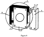
- the device according to the present invention is applicable to any type of lock comprising a striker 5 embedded in the doorframe of a door, a trunk 7 fixed against the door leaf and a locking bolt 1 slidable to fit into the striker 5.
- This device comprises a housing 2 having the shape of a "U" upside down forming a horizontal upper portion and two vertical side portions.
- the housing 2 is configured to be able, in use, to cap the trunk 7 of the lock .
- the upper part is able to rest on the upper surface of the box 7.
- the vertical lateral part situated on the right of the device consists of two arms 3, 3 'separated by a central space having a width of 9.4 mm. allowing to be placed on the trunk 7 between the trunk 7 and the keeper 5, letting through the space between these two arms 3, 3 'the bolt 1.
- the vertical side portion at the other end of the device (left side) consists of a full arm 6 adapted to be placed against the rear end of the bolt 1, namely the heel of the bolt 1, allowing, after study, to withstand the force of the pressure on the one by the bolt 1 when we try to slide it to open the lock.
- the housing (2) will have studied dimensions of the order of 80 mm in height (length of the lateral vertical parts), 78 mm in length (length of the upper horizontal part), 22.8 mm of width (width of vertical and horizontal parts of housing 2).
- the lateral vertical portions preferably have a plate thickness of 1 mm
- the upper horizontal portion preferably has a plate thickness of 2 mm.
- the side sections of the solid arm preferably have a width of 10 mm.
- the space between the two arms 3, 3 'can have a height of 60 mm and a width of 9.4 mm.
- each of the two arms 3, 3 ' has a width of 6.7 mm.
Landscapes
- Engineering & Computer Science (AREA)
- Mechanical Engineering (AREA)
- Closing And Opening Devices For Wings, And Checks For Wings (AREA)
- Wing Frames And Configurations (AREA)
- Lock And Its Accessories (AREA)
- Casings For Electric Apparatus (AREA)
Abstract
Description
- La présente invention concerne un dispositif pour bloquer l'ouverture d'un verrou de porte de l'intérieur.
- L'ouverture de verrou est possible depuis l'extérieur d'une maison même sans avoir de clefs. Nous pouvons donc, depuis l'extérieur, tourner le verrou et faire reculer le pêne de celui-ci à l'aide d'une clef ou d'un autre dispositif.
- Le document
FR539759 - Ainsi, le dispositif décrit dans le document
FR539759 - Il existe donc un besoin pour un dispositif adaptable sur tout type de verrou, notamment un verrou actionné par une clé, une tige, un bouton ou un gland.
- La présente invention vise à résoudre cet inconvénient de l'état antérieur de la technique, en proposant un dispositif apte à s'adapter à toutes les sortes de verrou comprenant un pêne non inclus dans l'encadrement de la porte.
- La présente invention a donc pour objet un dispositif pour bloquer le coulissement d'un pêne lors d'une tentative d'ouverture de verrou non désirée, lequel verrou comprend un coffre, une gâche et ledit pêne ayant une tête apte à s'engager dans la gâche en position fermée du verrou et un talon opposé à la tête, caractérisé en ce qu'il comporte un boîtier ayant la forme d'un « U » à l'envers, et ayant ainsi une partie supérieure horizontale et deux parties latérales verticales, dont une partie verticale arrière constituée d'un bras plein apte à se placer derrière le talon du pêne, et une partie verticale avant constituée de deux bras séparés par un espace et aptes à se situer entre le coffre et la gâche du verrou en position fermée de ce dernier, de façon à assurer le maintien du boîtier, en laissant passer le pêne à travers l'espace situé entre les deux bras, la partie supérieure horizontale venant reposer sur le coffre et le bras plein empêchant le coulissement du pêne dans la direction d'ouverture du verrou.
- De préférence, la partie verticale arrière du boîtier présente une section en C en coupe transversale, ayant une section centrale s'étendant en regard de la partie verticale avant, et deux sections latérales parallèles entre elles et s'étendant perpendiculairement à la section centrale en direction de la partie verticale avant.
- De préférence, les parties verticales avant et arrière ont la même longueur et la même largeur.
- L'espace entre les deux bras de la partie verticale avant peut avoir une largeur de 9,4 mm et, facultativement, une hauteur de 60 mm.
- Le boîtier peut avoir une hauteur de l'ordre de 80 mm, une longueur de l'ordre de 78 mm et une largeur de l'ordre de 22,8 mm.
- Les parties latérales verticales latérales peuvent avoir une épaisseur de 1 mm et la partie supérieure horizontale peut avoir une épaisseur de 2 mm.
Les sections latérales de la partie verticale arrière peuvent avoir une largeur de 10 mm. - Est ainsi divulgué un dispositif pour bloquer le coulissement du pêne lors d'une tentative d'ouverture de verrou non désirée, caractérisé en ce qu'il comporte un boîtier ayant la forme d'un « U » à l'envers. Le boîtier peut être constitué de deux bras à une extrémité du boîtier, et, d'un bras plein situé à l'autre extrémité du boîtier. Le boîtier peut venir se placer sur le coffre d'un verrou en position fermée. Le boîtier peut disposer de deux bras qui se positionnent entre le coffre et la gâche, laissant passer le pêne par l'évidement situé entre les deux bras. L'autre extrémité du boîtier peut être en un seul bras plein, se place derrière le pêne pour maintenir ce dernier en position verrou fermé.
- Pour mieux illustrer l'objet de la présente invention, on va en décrire ci-après, à titre illustratif et non limitatif, un mode de réalisation préféré, avec référence au dessin annexé.
- Sur ce dessin :
- la
Figure 1 est un schéma, en vue de face, du dispositif selon la présente invention ; - les
Figures 2 et 3 sont des schémas, en vue de côté (côté avant) et en vue de dessous respectivement, du dispositif selon la présente invention ; et - la
Figure 3 est une vue en perspective du dispositif selon la présente invention, appliqué sur un verrou en position fermée. - Comme on peut le voir sur la
Figure 4 , le dispositif selon la présente invention est applicable sut tout type de verrou comprenant une gâche 5 encastrée dans le chambranle d'une porte, un coffre 7 fixé contre le battant de la porte et un pêne 1 de verrouillage apte à coulisser pour s'insérer dans la gâche 5. - Ce dispositif comprend un boîtier 2 ayant la forme d'un « U » à l'envers formant une partie supérieure horizontale et deux parties latérales verticales. Afin d'assurer le blocage du pêne en translation dans le sens du déverrouillage et le blocage en translation du dispositif vis-à-vis du coffre 7, ce boîtier 2 est configuré pour être apte, en utilisation, à coiffer le coffre 7 du verrou. En particulier, la partie supérieure est apte à reposer sur la surface supérieure du coffre 7. La partie latérale verticale située sur la droite du dispositif est constituée de deux bras 3, 3' séparés par un espace central ayant une largeur de 9,4 mm permettant de se placer sur le coffre 7, entre le coffre 7 et la gâche 5, en laissant passer au travers de l'espace entre ces deux bras 3, 3' le pêne 1. La partie latérale verticale située à l'autre extrémité du dispositif (côté gauche) est constituée d'un bras plein 6 apte à se placer contre l'extrémité arrière du pêne 1, à savoir le talon du pêne 1, permettant, après étude, de supporter l'effort de la pression exercée sur celui-ci par le pêne 1 lorsque l'on tente de le faire coulisser afin d'ouvrir le verrou.
- A titre d'exemple, le boîtier (2) aura des dimensions étudiées de l'ordre de 80 mm de hauteur (longueur des parties verticales latérales), 78 mm de longueur (longueur de la partie horizontale supérieure), 22,8 mm de largeur (largeur des parties verticales et horizontale du boîtier 2). De plus, comme on peut le voir sur les
Figures 1 et 3 , les parties verticales latérale ont, de préférence, une épaisseur de plaque de 1mm, et la partie horizontale supérieur a, de préférence, une épaisseur de plaque de 2 mm. Comme on peut le voir sur laFigure 1 , les sections latérales du bras plein ont, de préférence, une largeur de 10 mm. Concernant la partie verticale avant, l'espace entre les deux bras 3, 3' peut avoir une hauteur de 60 mm et une largeur de 9,4 mm. Ainsi, chacun des deux bras 3, 3' a une largeur de 6,7 mm.
Claims (7)
- Dispositif pour bloquer le coulissement d'un pêne (1) lors d'une tentative d'ouverture de verrou non désirée, lequel verrou comprend un coffre (7), une gâche (5) et ledit pêne (1) ayant une tête apte à s'engager dans la gâche (5) en position fermée du verrou et un talon opposé à la tête, caractérisé en ce qu'il comporte un boîtier (2) ayant la forme d'un « U » à l'envers, et ayant ainsi une partie supérieure horizontale et deux parties latérales verticales (3, 3' ; 6), dont une partie verticale arrière (6) constituée d'un bras plein (6) apte à se placer derrière le talon du pêne (1), et une partie verticale avant (3, 3') constituée de deux bras (3, 3') séparés par un espace et aptes à se situer entre le coffre (7) et la gâche (5) du verrou en position fermée de ce dernier, de façon à assurer le maintien du boîtier (2), en laissant passer le pêne (1) à travers l'espace situé entre les deux bras (3, 3'), la partie supérieure horizontale venant reposer sur le coffre (7) et le bras plein (6) empêchant le coulissement du pêne (1) dans la direction d'ouverture du verrou.
- Dispositif selon la revendication 1, caractérisé en ce que la partie verticale arrière (6) du boîtier (2) présente une section en C en coupe transversale, ayant une section centrale s'étendant en regard de la partie verticale avant (3, 3'), et deux sections latérales parallèles entre elles et s'étendant perpendiculairement à la section centrale en direction de la partie verticale avant (3, 3').
- Dispositif selon l'une des revendications 1 et 2, caractérisé en ce que les parties verticales avant et arrière ont la même longueur et la même largeur.
- Dispositif selon l'une des revendications 1 à 3, caractérisé en ce que l'espace entre les deux bras (3, 3') de la partie verticale avant (3, 3') a une largeur de 9,4 mm et, facultativement, une hauteur de 60 mm.
- Dispositif selon la revendication 4, caractérisé en ce que le boîtier (2) a une hauteur de l'ordre de 80 mm, une longueur de l'ordre de 78 mm et une largeur de l'ordre de 22,8 mm.
- Dispositif selon la revendication 5, caractérisé en ce que les parties latérales verticales latérales ont une épaisseur de 1 mm et la partie supérieure horizontale a une épaisseur de 2 mm.
- Dispositif selon l'une des revendications 5 et 6, prises en dépendance de la revendication 2, caractérisé en ce que les sections latérales de la partie verticale arrière (6) ont une largeur de 10 mm.
Applications Claiming Priority (1)
| Application Number | Priority Date | Filing Date | Title |
|---|---|---|---|
| FR1601427A FR3056621B1 (fr) | 2016-09-29 | 2016-09-29 | Dispositif pour bloquer l'ouverture d'un verrou de porte de l'intérieur |
Publications (2)
| Publication Number | Publication Date |
|---|---|
| EP3301246A1 true EP3301246A1 (fr) | 2018-04-04 |
| EP3301246B1 EP3301246B1 (fr) | 2019-12-25 |
Family
ID=57906662
Family Applications (1)
| Application Number | Title | Priority Date | Filing Date |
|---|---|---|---|
| EP17194200.6A Active EP3301246B1 (fr) | 2016-09-29 | 2017-09-29 | Dispositif pour bloquer l'ouverture d'un verrou de porte de l'intérieur |
Country Status (2)
| Country | Link |
|---|---|
| EP (1) | EP3301246B1 (fr) |
| FR (1) | FR3056621B1 (fr) |
Citations (3)
| Publication number | Priority date | Publication date | Assignee | Title |
|---|---|---|---|---|
| US754280A (en) * | 1903-07-09 | 1904-03-08 | George W Caswell | Lock. |
| FR539759A (fr) * | 1920-12-31 | 1922-06-30 | Dispositif de sécurité applicable aux verrous de sûreté | |
| US3773369A (en) * | 1972-07-18 | 1973-11-20 | W Wersonick | Latch bolt guard |
-
2016
- 2016-09-29 FR FR1601427A patent/FR3056621B1/fr active Active
-
2017
- 2017-09-29 EP EP17194200.6A patent/EP3301246B1/fr active Active
Patent Citations (3)
| Publication number | Priority date | Publication date | Assignee | Title |
|---|---|---|---|---|
| US754280A (en) * | 1903-07-09 | 1904-03-08 | George W Caswell | Lock. |
| FR539759A (fr) * | 1920-12-31 | 1922-06-30 | Dispositif de sécurité applicable aux verrous de sûreté | |
| US3773369A (en) * | 1972-07-18 | 1973-11-20 | W Wersonick | Latch bolt guard |
Also Published As
| Publication number | Publication date |
|---|---|
| FR3056621B1 (fr) | 2021-06-25 |
| FR3056621A1 (fr) | 2018-03-30 |
| EP3301246B1 (fr) | 2019-12-25 |
Similar Documents
| Publication | Publication Date | Title |
|---|---|---|
| EP0952284B1 (fr) | Dispositif de verrouillage pour ouvrant coulissant | |
| EP1105583B1 (fr) | Dispositif d'obturation a verrouillage selectif | |
| EP0246172B1 (fr) | Ferrure de verrouillage, notamment pour ouvrant coulissant | |
| CA1297135C (fr) | Ferrure de verrouillage notamment pour ouvrant coulissant | |
| FR3002571A1 (fr) | Gache pour galet de verrouillage en t | |
| EP3301246B1 (fr) | Dispositif pour bloquer l'ouverture d'un verrou de porte de l'intérieur | |
| EP0504044B1 (fr) | Armoire à porte verrouillable et retournable, et système comportant une telle armoire | |
| BE1015014A4 (fr) | Ferrure de verrouillage d'ouvrant dotee pour sa fixation de moyens d'appui interieur et exterieur decales et ouvrant equipe d'une telle ferrure. | |
| FR2466594A1 (fr) | Cremone de porte | |
| FR3125551A1 (fr) | Verrou de portail | |
| EP0070576B2 (fr) | Crémone, en particulier crémone-serrure pour porte, porte-fenêtre ou analogue | |
| EP1900893B1 (fr) | Serrure a double pene | |
| FR2773579A1 (fr) | Ferrure de verrouillage pour porte, porte-fenetre ou analogue munie d'un pene demi-tour a rappel elastique en position de verrouillage | |
| BE1014947A3 (fr) | Ferrure de verrouillage d'ouvrant coulissant a boitier technique et parement distincts, procede de montage et ouvrant equipe d'une telle ferrure. | |
| EP1149973B1 (fr) | Dispositif de verrouillage pour vantaux de porte à deux battants | |
| FR2811696A1 (fr) | Ferrure de verrouillage d'ouvrant a mors d'appui interieur manoeuvrable en translation, procede de montage et ouvrant equipe d'une telle ferrure | |
| FR2982305A1 (fr) | Verrou pour un premier vantail d'un systeme a double vantail | |
| FR2861116A1 (fr) | Dispositif de securite anti-effraction pour serrure et notamment une serrure multipoints pour porte, fenetre ou chassis coulissant | |
| EP1433910B1 (fr) | Ferrure de verrouillage pour ouvrant coulissant | |
| EP1406528B1 (fr) | Coffre pour le stockage d'objets | |
| FR3002570A1 (fr) | Gache pour galet de verrouillage en t | |
| FR2846695A1 (fr) | Ensemble de blocage au sol d'au moins un vantail de portail notamment | |
| FR3057010A1 (fr) | Volet coulissant | |
| FR2821877A1 (fr) | Entrebailleur pour porte, fenetre ou similaire equipe d'une ferrure de verrouillage du type cremone | |
| FR2613409A1 (fr) | Mecanisme de condamnation pour volets roulants |
Legal Events
| Date | Code | Title | Description |
|---|---|---|---|
| PUAI | Public reference made under article 153(3) epc to a published international application that has entered the european phase |
Free format text: ORIGINAL CODE: 0009012 |
|
| STAA | Information on the status of an ep patent application or granted ep patent |
Free format text: STATUS: THE APPLICATION HAS BEEN PUBLISHED |
|
| AK | Designated contracting states |
Kind code of ref document: A1 Designated state(s): AL AT BE BG CH CY CZ DE DK EE ES FI FR GB GR HR HU IE IS IT LI LT LU LV MC MK MT NL NO PL PT RO RS SE SI SK SM TR |
|
| AX | Request for extension of the european patent |
Extension state: BA ME |
|
| STAA | Information on the status of an ep patent application or granted ep patent |
Free format text: STATUS: REQUEST FOR EXAMINATION WAS MADE |
|
| 17P | Request for examination filed |
Effective date: 20181001 |
|
| RBV | Designated contracting states (corrected) |
Designated state(s): AL AT BE BG CH CY CZ DE DK EE ES FI FR GB GR HR HU IE IS IT LI LT LU LV MC MK MT NL NO PL PT RO RS SE SI SK SM TR |
|
| GRAP | Despatch of communication of intention to grant a patent |
Free format text: ORIGINAL CODE: EPIDOSNIGR1 |
|
| STAA | Information on the status of an ep patent application or granted ep patent |
Free format text: STATUS: GRANT OF PATENT IS INTENDED |
|
| RIC1 | Information provided on ipc code assigned before grant |
Ipc: E05C 19/18 20060101ALN20190131BHEP Ipc: E05B 15/12 20060101AFI20190131BHEP |
|
| INTG | Intention to grant announced |
Effective date: 20190214 |
|
| RIC1 | Information provided on ipc code assigned before grant |
Ipc: E05B 15/12 20060101AFI20190205BHEP Ipc: E05C 19/18 20060101ALN20190205BHEP |
|
| GRAS | Grant fee paid |
Free format text: ORIGINAL CODE: EPIDOSNIGR3 |
|
| GRAJ | Information related to disapproval of communication of intention to grant by the applicant or resumption of examination proceedings by the epo deleted |
Free format text: ORIGINAL CODE: EPIDOSDIGR1 |
|
| GRAL | Information related to payment of fee for publishing/printing deleted |
Free format text: ORIGINAL CODE: EPIDOSDIGR3 |
|
| STAA | Information on the status of an ep patent application or granted ep patent |
Free format text: STATUS: REQUEST FOR EXAMINATION WAS MADE |
|
| GRAP | Despatch of communication of intention to grant a patent |
Free format text: ORIGINAL CODE: EPIDOSNIGR1 |
|
| STAA | Information on the status of an ep patent application or granted ep patent |
Free format text: STATUS: GRANT OF PATENT IS INTENDED |
|
| INTC | Intention to grant announced (deleted) | ||
| INTG | Intention to grant announced |
Effective date: 20190718 |
|
| RIC1 | Information provided on ipc code assigned before grant |
Ipc: E05B 15/12 20060101AFI20190705BHEP Ipc: E05C 19/18 20060101ALN20190705BHEP |
|
| GRAA | (expected) grant |
Free format text: ORIGINAL CODE: 0009210 |
|
| STAA | Information on the status of an ep patent application or granted ep patent |
Free format text: STATUS: THE PATENT HAS BEEN GRANTED |
|
| AK | Designated contracting states |
Kind code of ref document: B1 Designated state(s): AL AT BE BG CH CY CZ DE DK EE ES FI FR GB GR HR HU IE IS IT LI LT LU LV MC MK MT NL NO PL PT RO RS SE SI SK SM TR |
|
| REG | Reference to a national code |
Ref country code: GB Ref legal event code: FG4D Free format text: NOT ENGLISH |
|
| REG | Reference to a national code |
Ref country code: CH Ref legal event code: EP |
|
| REG | Reference to a national code |
Ref country code: AT Ref legal event code: REF Ref document number: 1217284 Country of ref document: AT Kind code of ref document: T Effective date: 20200115 |
|
| REG | Reference to a national code |
Ref country code: DE Ref legal event code: R096 Ref document number: 602017010043 Country of ref document: DE |
|
| REG | Reference to a national code |
Ref country code: IE Ref legal event code: FG4D Free format text: LANGUAGE OF EP DOCUMENT: FRENCH |
|
| REG | Reference to a national code |
Ref country code: NL Ref legal event code: MP Effective date: 20191225 |
|
| PG25 | Lapsed in a contracting state [announced via postgrant information from national office to epo] |
Ref country code: GR Free format text: LAPSE BECAUSE OF FAILURE TO SUBMIT A TRANSLATION OF THE DESCRIPTION OR TO PAY THE FEE WITHIN THE PRESCRIBED TIME-LIMIT Effective date: 20200326 Ref country code: LT Free format text: LAPSE BECAUSE OF FAILURE TO SUBMIT A TRANSLATION OF THE DESCRIPTION OR TO PAY THE FEE WITHIN THE PRESCRIBED TIME-LIMIT Effective date: 20191225 Ref country code: NO Free format text: LAPSE BECAUSE OF FAILURE TO SUBMIT A TRANSLATION OF THE DESCRIPTION OR TO PAY THE FEE WITHIN THE PRESCRIBED TIME-LIMIT Effective date: 20200325 Ref country code: BG Free format text: LAPSE BECAUSE OF FAILURE TO SUBMIT A TRANSLATION OF THE DESCRIPTION OR TO PAY THE FEE WITHIN THE PRESCRIBED TIME-LIMIT Effective date: 20200325 Ref country code: FI Free format text: LAPSE BECAUSE OF FAILURE TO SUBMIT A TRANSLATION OF THE DESCRIPTION OR TO PAY THE FEE WITHIN THE PRESCRIBED TIME-LIMIT Effective date: 20191225 Ref country code: LV Free format text: LAPSE BECAUSE OF FAILURE TO SUBMIT A TRANSLATION OF THE DESCRIPTION OR TO PAY THE FEE WITHIN THE PRESCRIBED TIME-LIMIT Effective date: 20191225 Ref country code: SE Free format text: LAPSE BECAUSE OF FAILURE TO SUBMIT A TRANSLATION OF THE DESCRIPTION OR TO PAY THE FEE WITHIN THE PRESCRIBED TIME-LIMIT Effective date: 20191225 |
|
| REG | Reference to a national code |
Ref country code: LT Ref legal event code: MG4D |
|
| PG25 | Lapsed in a contracting state [announced via postgrant information from national office to epo] |
Ref country code: HR Free format text: LAPSE BECAUSE OF FAILURE TO SUBMIT A TRANSLATION OF THE DESCRIPTION OR TO PAY THE FEE WITHIN THE PRESCRIBED TIME-LIMIT Effective date: 20191225 Ref country code: RS Free format text: LAPSE BECAUSE OF FAILURE TO SUBMIT A TRANSLATION OF THE DESCRIPTION OR TO PAY THE FEE WITHIN THE PRESCRIBED TIME-LIMIT Effective date: 20191225 |
|
| PG25 | Lapsed in a contracting state [announced via postgrant information from national office to epo] |
Ref country code: AL Free format text: LAPSE BECAUSE OF FAILURE TO SUBMIT A TRANSLATION OF THE DESCRIPTION OR TO PAY THE FEE WITHIN THE PRESCRIBED TIME-LIMIT Effective date: 20191225 |
|
| PG25 | Lapsed in a contracting state [announced via postgrant information from national office to epo] |
Ref country code: PT Free format text: LAPSE BECAUSE OF FAILURE TO SUBMIT A TRANSLATION OF THE DESCRIPTION OR TO PAY THE FEE WITHIN THE PRESCRIBED TIME-LIMIT Effective date: 20200520 Ref country code: CZ Free format text: LAPSE BECAUSE OF FAILURE TO SUBMIT A TRANSLATION OF THE DESCRIPTION OR TO PAY THE FEE WITHIN THE PRESCRIBED TIME-LIMIT Effective date: 20191225 Ref country code: NL Free format text: LAPSE BECAUSE OF FAILURE TO SUBMIT A TRANSLATION OF THE DESCRIPTION OR TO PAY THE FEE WITHIN THE PRESCRIBED TIME-LIMIT Effective date: 20191225 Ref country code: RO Free format text: LAPSE BECAUSE OF FAILURE TO SUBMIT A TRANSLATION OF THE DESCRIPTION OR TO PAY THE FEE WITHIN THE PRESCRIBED TIME-LIMIT Effective date: 20191225 Ref country code: EE Free format text: LAPSE BECAUSE OF FAILURE TO SUBMIT A TRANSLATION OF THE DESCRIPTION OR TO PAY THE FEE WITHIN THE PRESCRIBED TIME-LIMIT Effective date: 20191225 |
|
| PG25 | Lapsed in a contracting state [announced via postgrant information from national office to epo] |
Ref country code: SM Free format text: LAPSE BECAUSE OF FAILURE TO SUBMIT A TRANSLATION OF THE DESCRIPTION OR TO PAY THE FEE WITHIN THE PRESCRIBED TIME-LIMIT Effective date: 20191225 Ref country code: IS Free format text: LAPSE BECAUSE OF FAILURE TO SUBMIT A TRANSLATION OF THE DESCRIPTION OR TO PAY THE FEE WITHIN THE PRESCRIBED TIME-LIMIT Effective date: 20200425 Ref country code: SK Free format text: LAPSE BECAUSE OF FAILURE TO SUBMIT A TRANSLATION OF THE DESCRIPTION OR TO PAY THE FEE WITHIN THE PRESCRIBED TIME-LIMIT Effective date: 20191225 |
|
| REG | Reference to a national code |
Ref country code: DE Ref legal event code: R097 Ref document number: 602017010043 Country of ref document: DE |
|
| PG25 | Lapsed in a contracting state [announced via postgrant information from national office to epo] |
Ref country code: DK Free format text: LAPSE BECAUSE OF FAILURE TO SUBMIT A TRANSLATION OF THE DESCRIPTION OR TO PAY THE FEE WITHIN THE PRESCRIBED TIME-LIMIT Effective date: 20191225 Ref country code: ES Free format text: LAPSE BECAUSE OF FAILURE TO SUBMIT A TRANSLATION OF THE DESCRIPTION OR TO PAY THE FEE WITHIN THE PRESCRIBED TIME-LIMIT Effective date: 20191225 |
|
| PLBE | No opposition filed within time limit |
Free format text: ORIGINAL CODE: 0009261 |
|
| STAA | Information on the status of an ep patent application or granted ep patent |
Free format text: STATUS: NO OPPOSITION FILED WITHIN TIME LIMIT |
|
| REG | Reference to a national code |
Ref country code: AT Ref legal event code: MK05 Ref document number: 1217284 Country of ref document: AT Kind code of ref document: T Effective date: 20191225 |
|
| PG25 | Lapsed in a contracting state [announced via postgrant information from national office to epo] |
Ref country code: SI Free format text: LAPSE BECAUSE OF FAILURE TO SUBMIT A TRANSLATION OF THE DESCRIPTION OR TO PAY THE FEE WITHIN THE PRESCRIBED TIME-LIMIT Effective date: 20191225 |
|
| 26N | No opposition filed |
Effective date: 20200928 |
|
| PG25 | Lapsed in a contracting state [announced via postgrant information from national office to epo] |
Ref country code: AT Free format text: LAPSE BECAUSE OF FAILURE TO SUBMIT A TRANSLATION OF THE DESCRIPTION OR TO PAY THE FEE WITHIN THE PRESCRIBED TIME-LIMIT Effective date: 20191225 Ref country code: IT Free format text: LAPSE BECAUSE OF FAILURE TO SUBMIT A TRANSLATION OF THE DESCRIPTION OR TO PAY THE FEE WITHIN THE PRESCRIBED TIME-LIMIT Effective date: 20191225 |
|
| PG25 | Lapsed in a contracting state [announced via postgrant information from national office to epo] |
Ref country code: PL Free format text: LAPSE BECAUSE OF FAILURE TO SUBMIT A TRANSLATION OF THE DESCRIPTION OR TO PAY THE FEE WITHIN THE PRESCRIBED TIME-LIMIT Effective date: 20191225 |
|
| PG25 | Lapsed in a contracting state [announced via postgrant information from national office to epo] |
Ref country code: FR Free format text: LAPSE BECAUSE OF NON-PAYMENT OF DUE FEES Effective date: 20200930 |
|
| PGFP | Annual fee paid to national office [announced via postgrant information from national office to epo] |
Ref country code: CH Payment date: 20210927 Year of fee payment: 5 Ref country code: MC Payment date: 20210922 Year of fee payment: 5 Ref country code: IE Payment date: 20210921 Year of fee payment: 5 |
|
| PG25 | Lapsed in a contracting state [announced via postgrant information from national office to epo] |
Ref country code: TR Free format text: LAPSE BECAUSE OF FAILURE TO SUBMIT A TRANSLATION OF THE DESCRIPTION OR TO PAY THE FEE WITHIN THE PRESCRIBED TIME-LIMIT Effective date: 20191225 Ref country code: MT Free format text: LAPSE BECAUSE OF FAILURE TO SUBMIT A TRANSLATION OF THE DESCRIPTION OR TO PAY THE FEE WITHIN THE PRESCRIBED TIME-LIMIT Effective date: 20191225 Ref country code: CY Free format text: LAPSE BECAUSE OF FAILURE TO SUBMIT A TRANSLATION OF THE DESCRIPTION OR TO PAY THE FEE WITHIN THE PRESCRIBED TIME-LIMIT Effective date: 20191225 |
|
| PG25 | Lapsed in a contracting state [announced via postgrant information from national office to epo] |
Ref country code: MK Free format text: LAPSE BECAUSE OF FAILURE TO SUBMIT A TRANSLATION OF THE DESCRIPTION OR TO PAY THE FEE WITHIN THE PRESCRIBED TIME-LIMIT Effective date: 20191225 |
|
| PGFP | Annual fee paid to national office [announced via postgrant information from national office to epo] |
Ref country code: LU Payment date: 20220921 Year of fee payment: 6 Ref country code: GB Payment date: 20220919 Year of fee payment: 6 Ref country code: DE Payment date: 20220928 Year of fee payment: 6 |
|
| PGFP | Annual fee paid to national office [announced via postgrant information from national office to epo] |
Ref country code: BE Payment date: 20220926 Year of fee payment: 6 |
|
| PG25 | Lapsed in a contracting state [announced via postgrant information from national office to epo] |
Ref country code: MC Free format text: LAPSE BECAUSE OF NON-PAYMENT OF DUE FEES Effective date: 20220930 |
|
| REG | Reference to a national code |
Ref country code: CH Ref legal event code: PL |
|
| PG25 | Lapsed in a contracting state [announced via postgrant information from national office to epo] |
Ref country code: LI Free format text: LAPSE BECAUSE OF NON-PAYMENT OF DUE FEES Effective date: 20220930 Ref country code: IE Free format text: LAPSE BECAUSE OF NON-PAYMENT OF DUE FEES Effective date: 20220929 Ref country code: CH Free format text: LAPSE BECAUSE OF NON-PAYMENT OF DUE FEES Effective date: 20220930 |
|
| REG | Reference to a national code |
Ref country code: DE Ref legal event code: R119 Ref document number: 602017010043 Country of ref document: DE |
|
| PG25 | Lapsed in a contracting state [announced via postgrant information from national office to epo] |
Ref country code: LU Free format text: LAPSE BECAUSE OF NON-PAYMENT OF DUE FEES Effective date: 20230929 |
|
| REG | Reference to a national code |
Ref country code: BE Ref legal event code: MM Effective date: 20230930 |
|
| GBPC | Gb: european patent ceased through non-payment of renewal fee |
Effective date: 20230929 |
|
| PG25 | Lapsed in a contracting state [announced via postgrant information from national office to epo] |
Ref country code: LU Free format text: LAPSE BECAUSE OF NON-PAYMENT OF DUE FEES Effective date: 20230929 |
|
| PG25 | Lapsed in a contracting state [announced via postgrant information from national office to epo] |
Ref country code: GB Free format text: LAPSE BECAUSE OF NON-PAYMENT OF DUE FEES Effective date: 20230929 |
|
| PG25 | Lapsed in a contracting state [announced via postgrant information from national office to epo] |
Ref country code: GB Free format text: LAPSE BECAUSE OF NON-PAYMENT OF DUE FEES Effective date: 20230929 Ref country code: DE Free format text: LAPSE BECAUSE OF NON-PAYMENT OF DUE FEES Effective date: 20240403 |
|
| PG25 | Lapsed in a contracting state [announced via postgrant information from national office to epo] |
Ref country code: BE Free format text: LAPSE BECAUSE OF NON-PAYMENT OF DUE FEES Effective date: 20230930 |