EP3301263A1 - Besondere gestaltung einer turbinenabgassstruktur - Google Patents
Besondere gestaltung einer turbinenabgassstruktur Download PDFInfo
- Publication number
- EP3301263A1 EP3301263A1 EP16290192.0A EP16290192A EP3301263A1 EP 3301263 A1 EP3301263 A1 EP 3301263A1 EP 16290192 A EP16290192 A EP 16290192A EP 3301263 A1 EP3301263 A1 EP 3301263A1
- Authority
- EP
- European Patent Office
- Prior art keywords
- turbine exhaust
- exhaust structure
- casing
- pipe
- pressure
- Prior art date
- Legal status (The legal status is an assumption and is not a legal conclusion. Google has not performed a legal analysis and makes no representation as to the accuracy of the status listed.)
- Granted
Links
Images



Classifications
-
- F—MECHANICAL ENGINEERING; LIGHTING; HEATING; WEAPONS; BLASTING
- F01—MACHINES OR ENGINES IN GENERAL; ENGINE PLANTS IN GENERAL; STEAM ENGINES
- F01D—NON-POSITIVE DISPLACEMENT MACHINES OR ENGINES, e.g. STEAM TURBINES
- F01D9/00—Stators
- F01D9/06—Fluid supply conduits to nozzles or the like
-
- F—MECHANICAL ENGINEERING; LIGHTING; HEATING; WEAPONS; BLASTING
- F01—MACHINES OR ENGINES IN GENERAL; ENGINE PLANTS IN GENERAL; STEAM ENGINES
- F01D—NON-POSITIVE DISPLACEMENT MACHINES OR ENGINES, e.g. STEAM TURBINES
- F01D25/00—Component parts, details, or accessories, not provided for in, or of interest apart from, other groups
- F01D25/24—Casings; Casing parts, e.g. diaphragms, casing fastenings
-
- F—MECHANICAL ENGINEERING; LIGHTING; HEATING; WEAPONS; BLASTING
- F01—MACHINES OR ENGINES IN GENERAL; ENGINE PLANTS IN GENERAL; STEAM ENGINES
- F01D—NON-POSITIVE DISPLACEMENT MACHINES OR ENGINES, e.g. STEAM TURBINES
- F01D25/00—Component parts, details, or accessories, not provided for in, or of interest apart from, other groups
- F01D25/24—Casings; Casing parts, e.g. diaphragms, casing fastenings
- F01D25/243—Flange connections; Bolting arrangements
-
- F—MECHANICAL ENGINEERING; LIGHTING; HEATING; WEAPONS; BLASTING
- F01—MACHINES OR ENGINES IN GENERAL; ENGINE PLANTS IN GENERAL; STEAM ENGINES
- F01D—NON-POSITIVE DISPLACEMENT MACHINES OR ENGINES, e.g. STEAM TURBINES
- F01D25/00—Component parts, details, or accessories, not provided for in, or of interest apart from, other groups
- F01D25/30—Exhaust heads, chambers, or the like
-
- F—MECHANICAL ENGINEERING; LIGHTING; HEATING; WEAPONS; BLASTING
- F05—INDEXING SCHEMES RELATING TO ENGINES OR PUMPS IN VARIOUS SUBCLASSES OF CLASSES F01-F04
- F05B—INDEXING SCHEME RELATING TO WIND, SPRING, WEIGHT, INERTIA OR LIKE MOTORS, TO MACHINES OR ENGINES FOR LIQUIDS COVERED BY SUBCLASSES F03B, F03D AND F03G
- F05B2260/00—Function
- F05B2260/60—Fluid transfer
-
- F—MECHANICAL ENGINEERING; LIGHTING; HEATING; WEAPONS; BLASTING
- F05—INDEXING SCHEMES RELATING TO ENGINES OR PUMPS IN VARIOUS SUBCLASSES OF CLASSES F01-F04
- F05D—INDEXING SCHEME FOR ASPECTS RELATING TO NON-POSITIVE-DISPLACEMENT MACHINES OR ENGINES, GAS-TURBINES OR JET-PROPULSION PLANTS
- F05D2220/00—Application
- F05D2220/30—Application in turbines
- F05D2220/31—Application in turbines in steam turbines
-
- F—MECHANICAL ENGINEERING; LIGHTING; HEATING; WEAPONS; BLASTING
- F05—INDEXING SCHEMES RELATING TO ENGINES OR PUMPS IN VARIOUS SUBCLASSES OF CLASSES F01-F04
- F05D—INDEXING SCHEME FOR ASPECTS RELATING TO NON-POSITIVE-DISPLACEMENT MACHINES OR ENGINES, GAS-TURBINES OR JET-PROPULSION PLANTS
- F05D2230/00—Manufacture
- F05D2230/70—Disassembly methods
-
- F—MECHANICAL ENGINEERING; LIGHTING; HEATING; WEAPONS; BLASTING
- F05—INDEXING SCHEMES RELATING TO ENGINES OR PUMPS IN VARIOUS SUBCLASSES OF CLASSES F01-F04
- F05D—INDEXING SCHEME FOR ASPECTS RELATING TO NON-POSITIVE-DISPLACEMENT MACHINES OR ENGINES, GAS-TURBINES OR JET-PROPULSION PLANTS
- F05D2240/00—Components
- F05D2240/10—Stators
-
- F—MECHANICAL ENGINEERING; LIGHTING; HEATING; WEAPONS; BLASTING
- F05—INDEXING SCHEMES RELATING TO ENGINES OR PUMPS IN VARIOUS SUBCLASSES OF CLASSES F01-F04
- F05D—INDEXING SCHEME FOR ASPECTS RELATING TO NON-POSITIVE-DISPLACEMENT MACHINES OR ENGINES, GAS-TURBINES OR JET-PROPULSION PLANTS
- F05D2260/00—Function
- F05D2260/60—Fluid transfer
Definitions
- the present invention generally relates to power plant steam turbines and more particularly to a turbine exhaust structure, and even more particularly to an intermediate-pressure exhaust end, a part of a high-and-intermediate-pressure (HIP) module.
- HIP high-and-intermediate-pressure
- a power plant steam turbine is a device which converts thermal energy of pressurized steam to mechanical energy.
- the thermal energy is obtained by the production of steam by a boiler.
- the resulting steam flow is thus supplied to the steam turbine at the required pressure and temperature.
- the turbine converts the steam flow into a torque which is used for driving a rotor of an electric generator for the production of electrical energy.
- the rotor of the electric generator is driven by means of a turbine shaft that interconnects the rotor with the steam turbine.
- steam turbines comprise at least one high-pressure casing, at least one intermediate-pressure casing and at least one low-pressure casing.
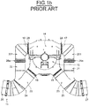
- Figure 1a shows a specific HIP casing 10 comprising an intermediate-pressure exhaust structure 11 connected to a combined high-pressure/intermediate pressure casing 12 thanks a vertical flange connection 13.
- intermediate-pressure casings usually comprise an upper element 14 and a lower element 15 which are connected to each other by means of a horizontal bolted flange.
- Each of the two elements 14, 15 comprises two outlets 16, 17 and 18, 19 such that two outlets are arranged on the left-hand side and two outlets are provided on the right hand side.
- Each outlet is connected to an exhaust pipe 20, 21, 22 and 23.
- the pipe 20, 21 is connected to the outlet 16, 17 thanks to a fabricated part 201, 211, said part 201, 211 comprising an elbow.
- the pipes are of specific design since the two pipes 20, 22 on the left-hand side are connected to each other and the two pipes 21, 23 on the right-hand side are also connected to each other.
- the intermediate-pressure casings comprise two Y-shaped exhaust pipes 24, 25.
- each of the two Y-shaped exhaust pipes 24 and 25 is connected to a further pipe 26, 27.
- the fabricated parts 201, 211 are connected to the upper element 14 thanks to connecting upper flanges 28 and 29, and to pipes 20, 21 thanks to connecting horizontal flanges 28a and 29a.
- the connecting upper flanges 28, 29 and the connecting horizontal flanges 28a and 29a have to be dismantled for the purpose of maintenance of the HIP casing 10, and have to be properly retightened thereafter.
- This configuration makes the opening of said HIP casing 10 difficult. Indeed, once the dismantling of the connecting upper flanges 28 and 29 and of the connecting horizontal flanges 28a and 29a is done, it is always difficult to retighten them suitably. Besides being difficult, these maintenance operations take a long time.
- the present invention aims at providing a turbine exhaust structure permitting to overcome the above drawbacks and which is easier to maintain as well as being economical to manufacture.
- the turbine exhaust structure comprises:
- Such a turbine exhaust structure is configured to be connected to the combined high-pressure/intermediate-pressure casing 12 as shown in Figure 1a .
- the first element is connected to the second element along a horizontal joint plane.
- the first element is an upper element and the second element is a lower element.
- the casing has a central aperture.
- the central aperture may extend from a first face to a second opposite face of the casing, the section of a first face central aperture being larger than the section of a second opposite face central aperture.
- the second element comprises at least two outlets, preferably two outlets, each connected to a connecting pipe.
- the second element is connected to the connecting pipe thanks to a welded connection.
- the length of the turbine exhaust structure varies from 6 to 12 meters, preferably from 9 to 10 meters.
- the width of the turbine exhaust structure may vary from 2 to 6 meters, preferably from 3 to 4 meters.
- the height of the turbine exhaust structure may vary from 6 to 12 meters, preferably from 8 to 9 meters.
- the second pipe is an elbow pipe.
- the turbine exhaust structure is a fabricated structure.
- the turbine exhaust structure is an intermediate pressure exhaust end.
- Another object of the invention relates to a high-and-intermediate-pressure casing comprising a high-pressure casing and a turbine exhaust structure according to an embodiment of the present invention.
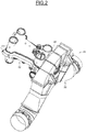
- the high-and-intermediate-pressure casing 31 comprises a turbine exhaust structure 30, which is an intermediate-pressure exhaust end 30, and a combined high-pressure/intermediate-pressure casing 32, said casing 32 being connected to the turbine exhaust structure 30 thanks to a vertical flange connection 33.
- the combined high-pressure/intermediate-pressure casing 32 is identical to the combined high-pressure/intermediate-pressure casing 12 represented on Figure 1a .
- the intermediate-pressure exhaust end 30 according to an embodiment of the present invention is configured to be connected to the different modules used in a known steam turbine.
- the interfaces of the intermediate-pressure exhaust end 30 are configured in such a way that the design of the other components constituting a known steam turbine, and intended to be associated to said intermediate-pressure exhaust end 30, does not need to be modified.
- the vertical flange connection 33 is identical to the one used in an intermediate-pressure exhaust end of the prior art like the vertical flange connection 13.
- the intermediate-pressure exhaust end 30 comprises a casing 34 divided into a first element 35 and a second element 36, which is connected to the first element.
- the intermediate-pressure exhaust end 30 also comprises two connecting pipes 37, 38 which are configured to be connected to a second pipe 39 and 40.
- the second pipe 39, 40 is an elbow pipe.
- the second element 36 comprises two outlets 41, 42 (not shown) of rectangular cross section.
- the connecting pipe 37, 38 is provided with a first end 371, 381, having a first section, and a second end 372, 382, having a second section.
- the second element 36 is connected to the connecting pipe 37, 38 thanks to a welded connection.
- the outlet 41, 42 is connected to the first end 371, 381 and the second end 372, 382 is configured to be connected to the second pipe 39, 40.
- the first element 35 is an upper element 35.
- the second element 36 is a lower element 36.
- the casing 34 has a central aperture 43 which extends from a first face 341, shown on Figure 3 , to a second opposite face 342 of the casing 34, shown on Figure 4 .
- a first face central aperture 431 has a first section and a second face central aperture 432 has a second section. The first section of the first face central aperture 431 is larger than the second section of the second face central aperture 432.
- the upper element 35 is connected to the lower element 36 along a horizontal joint plan by a plurality of studs and nuts 44 and also thanks to two supports 45 and 46 on the second opposite face 342, as shown on Figure 4 .
- the casing 34 comprises a plurality of outer reinforcements 47 on both the upper element 35 and the lower element 36.
- the outer reinforcements 47 of the lower element 36 extend radially from both the first face central aperture 431 and the second face central aperture 432.
- the outer reinforcements 47 of the upper element 35 extend radially from the first face central aperture 431 to the second face central aperture 432 and vice versa.
- the casing 34 also comprises a plurality of inner reinforcements 48 (not shown) located inside said casing 34.
- first face central aperture 431 of the casing 34 is configured to be connected with the combined high-pressure/intermediate-pressure casing 32 thanks to the vertical flange connection 33 and a plurality of studs and nuts 49, which are around the first face central aperture 431, and a sealing weld.
- the turbine exhaust end according to the present invention is very cost-efficient because it allows avoiding the use of Y-shaped pipes which are very difficult to manufacture, thereby reducing quantities of materials to be used. Indeed, it is estimated that the turbine exhaust end according to the present invention allows sparing around 15 tons of materials. Moreover, the turbine exhaust end according to the present invention is also very cost-efficient because said turbine exhaust end is a fabricated structure whereas the one described in Figure 1A is a foundry structure. This is particularly true with regard to large-scaled objects which are produced in small quantities.
- the interfaces of the intermediate-pressure exhaust end 30 are configured in such a way that the design of the other components constituting a known steam turbine, for example the diaphragms, and intended to be associated to said intermediate-pressure exhaust end 30, does not need to be modified.
Landscapes
- Engineering & Computer Science (AREA)
- Mechanical Engineering (AREA)
- General Engineering & Computer Science (AREA)
- Turbine Rotor Nozzle Sealing (AREA)
- Supercharger (AREA)
Priority Applications (5)
| Application Number | Priority Date | Filing Date | Title |
|---|---|---|---|
| EP16290192.0A EP3301263B1 (de) | 2016-10-03 | 2016-10-03 | Besondere gestaltung einer turbinenabgasstruktur |
| CN201780061564.8A CN109790756B (zh) | 2016-10-03 | 2017-09-29 | 具有特殊设计的涡轮排气结构 |
| PCT/EP2017/074776 WO2018065307A1 (en) | 2016-10-03 | 2017-09-29 | Turbine exhaust structure of particular design |
| JP2019516694A JP6746780B2 (ja) | 2016-10-03 | 2017-09-29 | 特殊な設計のタービン排気構造体 |
| US16/372,485 US11702960B2 (en) | 2016-10-03 | 2019-04-02 | Turbine exhaust structure of particular design |
Applications Claiming Priority (1)
| Application Number | Priority Date | Filing Date | Title |
|---|---|---|---|
| EP16290192.0A EP3301263B1 (de) | 2016-10-03 | 2016-10-03 | Besondere gestaltung einer turbinenabgasstruktur |
Publications (2)
| Publication Number | Publication Date |
|---|---|
| EP3301263A1 true EP3301263A1 (de) | 2018-04-04 |
| EP3301263B1 EP3301263B1 (de) | 2019-11-27 |
Family
ID=57944241
Family Applications (1)
| Application Number | Title | Priority Date | Filing Date |
|---|---|---|---|
| EP16290192.0A Active EP3301263B1 (de) | 2016-10-03 | 2016-10-03 | Besondere gestaltung einer turbinenabgasstruktur |
Country Status (5)
| Country | Link |
|---|---|
| US (1) | US11702960B2 (de) |
| EP (1) | EP3301263B1 (de) |
| JP (1) | JP6746780B2 (de) |
| CN (1) | CN109790756B (de) |
| WO (1) | WO2018065307A1 (de) |
Families Citing this family (3)
| Publication number | Priority date | Publication date | Assignee | Title |
|---|---|---|---|---|
| JP7566536B2 (ja) * | 2020-08-28 | 2024-10-15 | 東芝エネルギーシステムズ株式会社 | ガスタービンおよびガスタービンの製造方法 |
| KR102866621B1 (ko) * | 2020-12-28 | 2025-09-29 | 한화에어로스페이스 주식회사 | 개선된 용접부 구조를 구비하는 배기 덕트 어셈블리 및 이를 포함하는 비행체 |
| US12173610B2 (en) * | 2023-02-20 | 2024-12-24 | Solar Turbines Incorporated | System for coupling ducts in gas turbine engines for power generation applications |
Citations (2)
| Publication number | Priority date | Publication date | Assignee | Title |
|---|---|---|---|---|
| US20050072157A1 (en) * | 2003-10-06 | 2005-04-07 | Masaki Takahashi | Steam turbine |
| US20070014671A1 (en) * | 2005-07-07 | 2007-01-18 | Masahiko Arai | Pipe for steam turbine, manufacturing process of same, main steam pipe and reheat pipe for steam turbine, and steam turbine power plant using those pipes |
Family Cites Families (15)
| Publication number | Priority date | Publication date | Assignee | Title |
|---|---|---|---|---|
| US1269998A (en) * | 1915-02-01 | 1918-06-18 | Westinghouse Electric & Mfg Co | Steam-turbine. |
| US1372930A (en) * | 1917-01-31 | 1921-03-29 | British Westinghouse Electric | Condensing-steam-turbine installation |
| JPS5566605A (en) * | 1978-11-14 | 1980-05-20 | Toshiba Corp | Exhaust casing for steam turbine |
| US4622819A (en) * | 1985-01-29 | 1986-11-18 | Westinghouse Electric Corp. | Steam turbine exhaust pipe erosion prevention system |
| US4803841A (en) * | 1987-09-30 | 1989-02-14 | Westinghouse Electric Corp. | Moisture separator for steam turbine exhaust |
| US4986732A (en) * | 1989-08-03 | 1991-01-22 | Westinghouse Electric Corp. | Steam turbine crossover piping with reduced turning losses |
| US5174120A (en) * | 1991-03-08 | 1992-12-29 | Westinghouse Electric Corp. | Turbine exhaust arrangement for improved efficiency |
| US5257906A (en) * | 1992-06-30 | 1993-11-02 | Westinghouse Electric Corp. | Exhaust system for a turbomachine |
| JP4636965B2 (ja) * | 2005-08-04 | 2011-02-23 | 株式会社日立製作所 | タービン排気装置 |
| US8398367B2 (en) * | 2009-02-10 | 2013-03-19 | General Electric Company | Extraction unit for turbine and related method |
| EP2372111A1 (de) * | 2010-03-27 | 2011-10-05 | Alstom Technology Ltd | Niederdruckturbine mit zwei unabhängigen Kondensationssystemen |
| JP5499348B2 (ja) * | 2011-01-14 | 2014-05-21 | 株式会社日立製作所 | 蒸気タービンの排気装置 |
| US20130019600A1 (en) * | 2011-07-18 | 2013-01-24 | General Electric Company | Turbine exhaust arrangement |
| US20140047813A1 (en) * | 2012-08-17 | 2014-02-20 | Solar Turbines Incorporated | Exhaust collector with radial and circumferential flow breaks |
| CN205445696U (zh) * | 2016-02-22 | 2016-08-10 | 杭州汽轮机股份有限公司 | 工业汽轮机低背压焊接排汽缸 |
-
2016
- 2016-10-03 EP EP16290192.0A patent/EP3301263B1/de active Active
-
2017
- 2017-09-29 JP JP2019516694A patent/JP6746780B2/ja active Active
- 2017-09-29 CN CN201780061564.8A patent/CN109790756B/zh active Active
- 2017-09-29 WO PCT/EP2017/074776 patent/WO2018065307A1/en not_active Ceased
-
2019
- 2019-04-02 US US16/372,485 patent/US11702960B2/en active Active
Patent Citations (2)
| Publication number | Priority date | Publication date | Assignee | Title |
|---|---|---|---|---|
| US20050072157A1 (en) * | 2003-10-06 | 2005-04-07 | Masaki Takahashi | Steam turbine |
| US20070014671A1 (en) * | 2005-07-07 | 2007-01-18 | Masahiko Arai | Pipe for steam turbine, manufacturing process of same, main steam pipe and reheat pipe for steam turbine, and steam turbine power plant using those pipes |
Also Published As
| Publication number | Publication date |
|---|---|
| EP3301263B1 (de) | 2019-11-27 |
| US11702960B2 (en) | 2023-07-18 |
| CN109790756B (zh) | 2022-07-22 |
| WO2018065307A1 (en) | 2018-04-12 |
| JP2019534972A (ja) | 2019-12-05 |
| JP6746780B2 (ja) | 2020-08-26 |
| US20190226360A1 (en) | 2019-07-25 |
| CN109790756A (zh) | 2019-05-21 |
Similar Documents
| Publication | Publication Date | Title |
|---|---|---|
| US11702960B2 (en) | Turbine exhaust structure of particular design | |
| US9027351B2 (en) | System and method for packaging and transporting a gas turbine | |
| CN107110408B (zh) | 处于高温、高压瞬态以及在循环加载下的异种管道接头 | |
| EP2837770B1 (de) | Dampfturbine mit vollständiger Beaufschlagung | |
| RU2600217C2 (ru) | Способ ограничения высоты свободного пространства, устройство для снятия верхнего выпускного патрубка паровой турбины и паровая турбина | |
| EP3155319B1 (de) | Konstruktion eines modularen wärmerückgewinnungsdampfgenerators | |
| KR101655461B1 (ko) | 터빈용 추출 유닛 및 관련 방법 | |
| US9458737B2 (en) | Adjustable bracing apparatus and assembly method for gas turbine exhaust diffuser | |
| JP2018524515A (ja) | 蒸気タービンのための排気ケーシング及び組立システム | |
| EP2568143A2 (de) | Leitungsanordnung und Verfahren zum Verbinden eines Innen- und eines Außengehäuses in einem Turbinensystem | |
| US20180347285A1 (en) | Plant module with perforated beams | |
| US20130078089A1 (en) | Steam turbine single shell extraction lp casing | |
| JP6514490B2 (ja) | 内部で補強された高寿命な排熱回収ボイラ装置 | |
| CN203515696U (zh) | 排汽缸与冷凝器之间的连接结构及其工业汽轮机 | |
| US20160356166A1 (en) | Steam turbine | |
| US20140119886A1 (en) | Turbine cowling system | |
| CN204402757U (zh) | 小型风力发电机 | |
| JP6249927B2 (ja) | 蒸気タービン | |
| CN103953811A (zh) | 泵试验用快速接头 | |
| CN203559941U (zh) | 工业汽轮机 | |
| EP2922182A1 (de) | Werkzeug und Verfahren zur Montage eines Generators | |
| CN101725380A (zh) | 蒸汽涡轮 | |
| RU94288U1 (ru) | Осевая гидротурбина | |
| Orlik et al. | Reduction of air inflows in condensers of 200-MW power units | |
| CN104047641A (zh) | 汽轮机上阀门与汽缸的连接结构 |
Legal Events
| Date | Code | Title | Description |
|---|---|---|---|
| PUAI | Public reference made under article 153(3) epc to a published international application that has entered the european phase |
Free format text: ORIGINAL CODE: 0009012 |
|
| STAA | Information on the status of an ep patent application or granted ep patent |
Free format text: STATUS: THE APPLICATION HAS BEEN PUBLISHED |
|
| AK | Designated contracting states |
Kind code of ref document: A1 Designated state(s): AL AT BE BG CH CY CZ DE DK EE ES FI FR GB GR HR HU IE IS IT LI LT LU LV MC MK MT NL NO PL PT RO RS SE SI SK SM TR |
|
| AX | Request for extension of the european patent |
Extension state: BA ME |
|
| STAA | Information on the status of an ep patent application or granted ep patent |
Free format text: STATUS: REQUEST FOR EXAMINATION WAS MADE |
|
| 17P | Request for examination filed |
Effective date: 20181004 |
|
| RBV | Designated contracting states (corrected) |
Designated state(s): AL AT BE BG CH CY CZ DE DK EE ES FI FR GB GR HR HU IE IS IT LI LT LU LV MC MK MT NL NO PL PT RO RS SE SI SK SM TR |
|
| GRAP | Despatch of communication of intention to grant a patent |
Free format text: ORIGINAL CODE: EPIDOSNIGR1 |
|
| STAA | Information on the status of an ep patent application or granted ep patent |
Free format text: STATUS: GRANT OF PATENT IS INTENDED |
|
| INTG | Intention to grant announced |
Effective date: 20190521 |
|
| GRAS | Grant fee paid |
Free format text: ORIGINAL CODE: EPIDOSNIGR3 |
|
| GRAA | (expected) grant |
Free format text: ORIGINAL CODE: 0009210 |
|
| STAA | Information on the status of an ep patent application or granted ep patent |
Free format text: STATUS: THE PATENT HAS BEEN GRANTED |
|
| AK | Designated contracting states |
Kind code of ref document: B1 Designated state(s): AL AT BE BG CH CY CZ DE DK EE ES FI FR GB GR HR HU IE IS IT LI LT LU LV MC MK MT NL NO PL PT RO RS SE SI SK SM TR |
|
| REG | Reference to a national code |
Ref country code: GB Ref legal event code: FG4D |
|
| REG | Reference to a national code |
Ref country code: CH Ref legal event code: EP |
|
| REG | Reference to a national code |
Ref country code: AT Ref legal event code: REF Ref document number: 1206863 Country of ref document: AT Kind code of ref document: T Effective date: 20191215 |
|
| REG | Reference to a national code |
Ref country code: DE Ref legal event code: R096 Ref document number: 602016025014 Country of ref document: DE |
|
| REG | Reference to a national code |
Ref country code: IE Ref legal event code: FG4D |
|
| REG | Reference to a national code |
Ref country code: FI Ref legal event code: FGE |
|
| REG | Reference to a national code |
Ref country code: NL Ref legal event code: MP Effective date: 20191127 |
|
| REG | Reference to a national code |
Ref country code: LT Ref legal event code: MG4D |
|
| PG25 | Lapsed in a contracting state [announced via postgrant information from national office to epo] |
Ref country code: LV Free format text: LAPSE BECAUSE OF FAILURE TO SUBMIT A TRANSLATION OF THE DESCRIPTION OR TO PAY THE FEE WITHIN THE PRESCRIBED TIME-LIMIT Effective date: 20191127 Ref country code: SE Free format text: LAPSE BECAUSE OF FAILURE TO SUBMIT A TRANSLATION OF THE DESCRIPTION OR TO PAY THE FEE WITHIN THE PRESCRIBED TIME-LIMIT Effective date: 20191127 Ref country code: GR Free format text: LAPSE BECAUSE OF FAILURE TO SUBMIT A TRANSLATION OF THE DESCRIPTION OR TO PAY THE FEE WITHIN THE PRESCRIBED TIME-LIMIT Effective date: 20200228 Ref country code: LT Free format text: LAPSE BECAUSE OF FAILURE TO SUBMIT A TRANSLATION OF THE DESCRIPTION OR TO PAY THE FEE WITHIN THE PRESCRIBED TIME-LIMIT Effective date: 20191127 Ref country code: BG Free format text: LAPSE BECAUSE OF FAILURE TO SUBMIT A TRANSLATION OF THE DESCRIPTION OR TO PAY THE FEE WITHIN THE PRESCRIBED TIME-LIMIT Effective date: 20200227 Ref country code: NO Free format text: LAPSE BECAUSE OF FAILURE TO SUBMIT A TRANSLATION OF THE DESCRIPTION OR TO PAY THE FEE WITHIN THE PRESCRIBED TIME-LIMIT Effective date: 20200227 Ref country code: NL Free format text: LAPSE BECAUSE OF FAILURE TO SUBMIT A TRANSLATION OF THE DESCRIPTION OR TO PAY THE FEE WITHIN THE PRESCRIBED TIME-LIMIT Effective date: 20191127 |
|
| PG25 | Lapsed in a contracting state [announced via postgrant information from national office to epo] |
Ref country code: HR Free format text: LAPSE BECAUSE OF FAILURE TO SUBMIT A TRANSLATION OF THE DESCRIPTION OR TO PAY THE FEE WITHIN THE PRESCRIBED TIME-LIMIT Effective date: 20191127 Ref country code: IS Free format text: LAPSE BECAUSE OF FAILURE TO SUBMIT A TRANSLATION OF THE DESCRIPTION OR TO PAY THE FEE WITHIN THE PRESCRIBED TIME-LIMIT Effective date: 20200327 Ref country code: RS Free format text: LAPSE BECAUSE OF FAILURE TO SUBMIT A TRANSLATION OF THE DESCRIPTION OR TO PAY THE FEE WITHIN THE PRESCRIBED TIME-LIMIT Effective date: 20191127 |
|
| PG25 | Lapsed in a contracting state [announced via postgrant information from national office to epo] |
Ref country code: AL Free format text: LAPSE BECAUSE OF FAILURE TO SUBMIT A TRANSLATION OF THE DESCRIPTION OR TO PAY THE FEE WITHIN THE PRESCRIBED TIME-LIMIT Effective date: 20191127 |
|
| PG25 | Lapsed in a contracting state [announced via postgrant information from national office to epo] |
Ref country code: DK Free format text: LAPSE BECAUSE OF FAILURE TO SUBMIT A TRANSLATION OF THE DESCRIPTION OR TO PAY THE FEE WITHIN THE PRESCRIBED TIME-LIMIT Effective date: 20191127 Ref country code: RO Free format text: LAPSE BECAUSE OF FAILURE TO SUBMIT A TRANSLATION OF THE DESCRIPTION OR TO PAY THE FEE WITHIN THE PRESCRIBED TIME-LIMIT Effective date: 20191127 Ref country code: PT Free format text: LAPSE BECAUSE OF FAILURE TO SUBMIT A TRANSLATION OF THE DESCRIPTION OR TO PAY THE FEE WITHIN THE PRESCRIBED TIME-LIMIT Effective date: 20200419 Ref country code: EE Free format text: LAPSE BECAUSE OF FAILURE TO SUBMIT A TRANSLATION OF THE DESCRIPTION OR TO PAY THE FEE WITHIN THE PRESCRIBED TIME-LIMIT Effective date: 20191127 Ref country code: ES Free format text: LAPSE BECAUSE OF FAILURE TO SUBMIT A TRANSLATION OF THE DESCRIPTION OR TO PAY THE FEE WITHIN THE PRESCRIBED TIME-LIMIT Effective date: 20191127 Ref country code: CZ Free format text: LAPSE BECAUSE OF FAILURE TO SUBMIT A TRANSLATION OF THE DESCRIPTION OR TO PAY THE FEE WITHIN THE PRESCRIBED TIME-LIMIT Effective date: 20191127 |
|
| REG | Reference to a national code |
Ref country code: DE Ref legal event code: R097 Ref document number: 602016025014 Country of ref document: DE |
|
| PG25 | Lapsed in a contracting state [announced via postgrant information from national office to epo] |
Ref country code: SM Free format text: LAPSE BECAUSE OF FAILURE TO SUBMIT A TRANSLATION OF THE DESCRIPTION OR TO PAY THE FEE WITHIN THE PRESCRIBED TIME-LIMIT Effective date: 20191127 Ref country code: SK Free format text: LAPSE BECAUSE OF FAILURE TO SUBMIT A TRANSLATION OF THE DESCRIPTION OR TO PAY THE FEE WITHIN THE PRESCRIBED TIME-LIMIT Effective date: 20191127 |
|
| REG | Reference to a national code |
Ref country code: AT Ref legal event code: MK05 Ref document number: 1206863 Country of ref document: AT Kind code of ref document: T Effective date: 20191127 |
|
| PLBE | No opposition filed within time limit |
Free format text: ORIGINAL CODE: 0009261 |
|
| STAA | Information on the status of an ep patent application or granted ep patent |
Free format text: STATUS: NO OPPOSITION FILED WITHIN TIME LIMIT |
|
| 26N | No opposition filed |
Effective date: 20200828 |
|
| PG25 | Lapsed in a contracting state [announced via postgrant information from national office to epo] |
Ref country code: AT Free format text: LAPSE BECAUSE OF FAILURE TO SUBMIT A TRANSLATION OF THE DESCRIPTION OR TO PAY THE FEE WITHIN THE PRESCRIBED TIME-LIMIT Effective date: 20191127 Ref country code: PL Free format text: LAPSE BECAUSE OF FAILURE TO SUBMIT A TRANSLATION OF THE DESCRIPTION OR TO PAY THE FEE WITHIN THE PRESCRIBED TIME-LIMIT Effective date: 20191127 Ref country code: SI Free format text: LAPSE BECAUSE OF FAILURE TO SUBMIT A TRANSLATION OF THE DESCRIPTION OR TO PAY THE FEE WITHIN THE PRESCRIBED TIME-LIMIT Effective date: 20191127 |
|
| PG25 | Lapsed in a contracting state [announced via postgrant information from national office to epo] |
Ref country code: IT Free format text: LAPSE BECAUSE OF FAILURE TO SUBMIT A TRANSLATION OF THE DESCRIPTION OR TO PAY THE FEE WITHIN THE PRESCRIBED TIME-LIMIT Effective date: 20191127 |
|
| REG | Reference to a national code |
Ref country code: DE Ref legal event code: R119 Ref document number: 602016025014 Country of ref document: DE |
|
| REG | Reference to a national code |
Ref country code: CH Ref legal event code: PL |
|
| PG25 | Lapsed in a contracting state [announced via postgrant information from national office to epo] |
Ref country code: LU Free format text: LAPSE BECAUSE OF NON-PAYMENT OF DUE FEES Effective date: 20201003 Ref country code: MC Free format text: LAPSE BECAUSE OF FAILURE TO SUBMIT A TRANSLATION OF THE DESCRIPTION OR TO PAY THE FEE WITHIN THE PRESCRIBED TIME-LIMIT Effective date: 20191127 |
|
| REG | Reference to a national code |
Ref country code: BE Ref legal event code: MM Effective date: 20201031 |
|
| PG25 | Lapsed in a contracting state [announced via postgrant information from national office to epo] |
Ref country code: DE Free format text: LAPSE BECAUSE OF NON-PAYMENT OF DUE FEES Effective date: 20210501 |
|
| PG25 | Lapsed in a contracting state [announced via postgrant information from national office to epo] |
Ref country code: LI Free format text: LAPSE BECAUSE OF NON-PAYMENT OF DUE FEES Effective date: 20201031 Ref country code: BE Free format text: LAPSE BECAUSE OF NON-PAYMENT OF DUE FEES Effective date: 20201031 Ref country code: CH Free format text: LAPSE BECAUSE OF NON-PAYMENT OF DUE FEES Effective date: 20201031 |
|
| PG25 | Lapsed in a contracting state [announced via postgrant information from national office to epo] |
Ref country code: IE Free format text: LAPSE BECAUSE OF NON-PAYMENT OF DUE FEES Effective date: 20201003 |
|
| PG25 | Lapsed in a contracting state [announced via postgrant information from national office to epo] |
Ref country code: MT Free format text: LAPSE BECAUSE OF FAILURE TO SUBMIT A TRANSLATION OF THE DESCRIPTION OR TO PAY THE FEE WITHIN THE PRESCRIBED TIME-LIMIT Effective date: 20191127 Ref country code: CY Free format text: LAPSE BECAUSE OF FAILURE TO SUBMIT A TRANSLATION OF THE DESCRIPTION OR TO PAY THE FEE WITHIN THE PRESCRIBED TIME-LIMIT Effective date: 20191127 |
|
| PG25 | Lapsed in a contracting state [announced via postgrant information from national office to epo] |
Ref country code: MK Free format text: LAPSE BECAUSE OF FAILURE TO SUBMIT A TRANSLATION OF THE DESCRIPTION OR TO PAY THE FEE WITHIN THE PRESCRIBED TIME-LIMIT Effective date: 20191127 |
|
| P01 | Opt-out of the competence of the unified patent court (upc) registered |
Effective date: 20230523 |
|
| REG | Reference to a national code |
Ref country code: FI Ref legal event code: PCE Owner name: ARABELLE TECHNOLOGIES |
|
| REG | Reference to a national code |
Ref country code: GB Ref legal event code: 732E Free format text: REGISTERED BETWEEN 20250213 AND 20250219 |
|
| REG | Reference to a national code |
Ref country code: GB Ref legal event code: 732E Free format text: REGISTERED BETWEEN 20250619 AND 20250625 |
|
| PGFP | Annual fee paid to national office [announced via postgrant information from national office to epo] |
Ref country code: FI Payment date: 20250923 Year of fee payment: 10 |
|
| PGFP | Annual fee paid to national office [announced via postgrant information from national office to epo] |
Ref country code: TR Payment date: 20250926 Year of fee payment: 10 |
|
| PGFP | Annual fee paid to national office [announced via postgrant information from national office to epo] |
Ref country code: GB Payment date: 20250923 Year of fee payment: 10 |
|
| PGFP | Annual fee paid to national office [announced via postgrant information from national office to epo] |
Ref country code: FR Payment date: 20250924 Year of fee payment: 10 |
|
| REG | Reference to a national code |
Ref country code: FI Ref legal event code: PCE Owner name: ARABELLE SOLUTIONS FRANCE, FR |