EP3301274A1 - Kühlschaltkreis für ein kraftfahrzeug - Google Patents
Kühlschaltkreis für ein kraftfahrzeug Download PDFInfo
- Publication number
- EP3301274A1 EP3301274A1 EP17194021.6A EP17194021A EP3301274A1 EP 3301274 A1 EP3301274 A1 EP 3301274A1 EP 17194021 A EP17194021 A EP 17194021A EP 3301274 A1 EP3301274 A1 EP 3301274A1
- Authority
- EP
- European Patent Office
- Prior art keywords
- degassing
- cooling
- cooling loop
- loop
- cooling circuit
- Prior art date
- Legal status (The legal status is an assumption and is not a legal conclusion. Google has not performed a legal analysis and makes no representation as to the accuracy of the status listed.)
- Granted
Links
Images


Classifications
-
- F—MECHANICAL ENGINEERING; LIGHTING; HEATING; WEAPONS; BLASTING
- F01—MACHINES OR ENGINES IN GENERAL; ENGINE PLANTS IN GENERAL; STEAM ENGINES
- F01P—COOLING OF MACHINES OR ENGINES IN GENERAL; COOLING OF INTERNAL-COMBUSTION ENGINES
- F01P11/00—Component parts, details, or accessories not provided for in, or of interest apart from, groups F01P1/00 - F01P9/00
- F01P11/02—Liquid-coolant filling, overflow, venting, or draining devices
- F01P11/028—Deaeration devices
-
- F—MECHANICAL ENGINEERING; LIGHTING; HEATING; WEAPONS; BLASTING
- F01—MACHINES OR ENGINES IN GENERAL; ENGINE PLANTS IN GENERAL; STEAM ENGINES
- F01P—COOLING OF MACHINES OR ENGINES IN GENERAL; COOLING OF INTERNAL-COMBUSTION ENGINES
- F01P7/00—Controlling of coolant flow
- F01P7/14—Controlling of coolant flow the coolant being liquid
- F01P7/16—Controlling of coolant flow the coolant being liquid by thermostatic control
- F01P7/165—Controlling of coolant flow the coolant being liquid by thermostatic control characterised by systems with two or more loops
-
- F—MECHANICAL ENGINEERING; LIGHTING; HEATING; WEAPONS; BLASTING
- F01—MACHINES OR ENGINES IN GENERAL; ENGINE PLANTS IN GENERAL; STEAM ENGINES
- F01P—COOLING OF MACHINES OR ENGINES IN GENERAL; COOLING OF INTERNAL-COMBUSTION ENGINES
- F01P11/00—Component parts, details, or accessories not provided for in, or of interest apart from, groups F01P1/00 - F01P9/00
- F01P11/02—Liquid-coolant filling, overflow, venting, or draining devices
- F01P11/029—Expansion reservoirs
-
- F—MECHANICAL ENGINEERING; LIGHTING; HEATING; WEAPONS; BLASTING
- F01—MACHINES OR ENGINES IN GENERAL; ENGINE PLANTS IN GENERAL; STEAM ENGINES
- F01P—COOLING OF MACHINES OR ENGINES IN GENERAL; COOLING OF INTERNAL-COMBUSTION ENGINES
- F01P2050/00—Applications
- F01P2050/24—Hybrid vehicles
-
- F—MECHANICAL ENGINEERING; LIGHTING; HEATING; WEAPONS; BLASTING
- F01—MACHINES OR ENGINES IN GENERAL; ENGINE PLANTS IN GENERAL; STEAM ENGINES
- F01P—COOLING OF MACHINES OR ENGINES IN GENERAL; COOLING OF INTERNAL-COMBUSTION ENGINES
- F01P7/00—Controlling of coolant flow
- F01P7/14—Controlling of coolant flow the coolant being liquid
- F01P7/16—Controlling of coolant flow the coolant being liquid by thermostatic control
Definitions
- the present invention relates to a cooling device and a cooling method for motor vehicles.
- thermal regulation loop is meant a circuit in which circulates a heat transfer fluid which regulates the temperature of a mechanical member by removing the thermal energy produced during the operation of this body.
- certain equipment such as the degassing box, may be common to several control loops.
- Degassing is a function of the engine in which the air or gas bubbles that are present in the coolant are purged.
- Degassing is an important function because the presence of air bubbles in the coolant has a deleterious effect on the quality of the cooling, and therefore does not allow the engine operation in optimal conditions; this can lead to uncontrolled thermal conditions with consequences in terms of reliability or durability of organs and environmental nuisance.
- the high temperature control loop has a constant need for degassing because the coolant which is in contact with hot spots of the engine - cooling of the cylinder head - can vaporize punctually and therefore, generate gas bubbles continuously while the control loops at low or very low temperature have a need for degassing when they start up but do not generate gas bubbles during their operation.
- a degassing box common to a high temperature cooling loop and to one or more cooling loops at a lower temperature is have a detrimental effect on cooling operation at lower temperature.
- an object of the invention is to provide a cooling circuit with several cooling loops pooling the degassing box without compromising the operation of each cooling loop.
- the invention relates to a cooling circuit for a motor vehicle comprising a first cooling loop designed to thermoregulate a first member and at least a second cooling loop designed to thermoregulate a second member, the first loop.
- I and at least one second cooling loop are fluidly connected to a single degassing box characterized in that each cooling loop connected to said degassing box comprises a degassing module, the degassing module being provided with a porous element hydrophobic by which escape air bubbles contained in said cooling loop I, II; III to join the degassing box.
- the invention thus provides a cooling circuit which ensures continuous degassing of multiple cooling loops with a single degassing box.
- each cooling loop comprises a thermostatic control box on which is disposed the degassing module.
- each cooling loop comprises a degassing branch connecting the degassing module of each cooling loop to the degassing box.
- the degassing module comprises a body in which circulates the coolant of a cooling loop and a cover in which the degassing branch is stitched, the hydrophobic porous element being interposed between the body and lid.
- the cover may have an array of ribs against which the porous hydrophobic element bears.
- the hydrophobic porous element may comprise a porous membrane superimposed on a prefiltering medium.
- a peripheral seal seals the hydrophobic porous element.
- the degassing module may have an input connection and an output connection offset relative to each other.
- each cooling loop comprises at least one pump, an exchanger, a radiator.
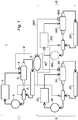
- the invention proposes a cooling circuit 1 for a vehicle comprising a plurality of cooling loops.
- the cooling circuit 1 comprises three cooling loops, namely: a cooling loop with high temperature I, a low temperature cooling loop II and a very low temperature cooling loop III.
- the high temperature cooling loop I comprises a high temperature exchanger 2 with the vehicle's heat engine, a high temperature radiator 3.
- a pump 4 circulates a glycol type cooling fluid.
- thermostatic control unit 5 which controls the cooling fluid circuit according to its operating temperature.
- a stitching is provided on the thermostatic housing 5 to make a connection with a single degassing box 6.
- the thermostatic control box 5 is equipped with a degassing module 8 which has a porous and hydrophobic element.
- hydrophobic porous element is meant an element which allows the passage of air or gas but which remains liquid-tight.
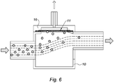
- the hydrophobic porous element 11 in the degassing module 10 in which the cooling fluid circulates in the high temperature cooling loop, the hydrophobic porous element 11 being in line with the a branch of degassing 9 is the so-called branch that connects the thermostatic control box to the degassing box 6.
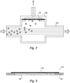
- the hydrophobic porous element 11 is a complex, as can be seen in the figure 3 , comprising a porous membrane 13 - for example, a polymer such as a polypropylene, a polyethylene or a PTFE - and a prefiltering medium 14 which makes it possible to prevent clogging of the microperforations of which the porous membrane 13 is provided.
- the hydrophobic porous member 11 may further include a seal 15; this seal 15 may be of elastomeric material and may preferably be fixed on the microporous membrane 13 and the prefilter media 14 by overmolding.
- the porous hydrophobic element 11 is interposed between the body 10 and a cover 16 which may be provided with a network of ribs 17; these ribs 17 serve to provide a support for the porous hydrophobic element 11.
- hydrophobic porous element not with a hydrophobic porous medium in the form of a membrane but with a hydrophobic porous media in the form of a porous ceramic or a sintered powder.
- the figure 5 shows an alternative embodiment of the degassing module 8 in which the inlet connection and the outlet connection of the degassing module 8 are offset relative to each other so that the flow of coolant maintain the hydrophobic porous element 11 in a state of cleanliness by preventing impurities from being deposited therein.
- the low temperature cooling loop II comprises a low temperature exchanger 20 with, for example, power electronics components (inverter, charger ...) of the electric propulsion chain or a low temperature radiator 30.
- a pump 40 ensures the circulation of the cooling fluid.
- the low temperature cooling loop II is also provided with a thermostatic control unit 50 which makes it possible to control the cooling fluid circuit as a function of the temperature.
- a tapping is provided on the thermostatic box 50 to make a connection with the degassing box 6.
- a degassing branch 90 ensures the fluid connection between the thermostatic box 50 and the degassing box 6.
- a degassing module 80 is placed for example on the thermostatic box 50 to allow the extraction of any air bubbles that are present in suspension in the coolant.
- the very low temperature cooling loop III comprises a very low temperature exchanger 200 with, for example, the battery of the electric propulsion system and a very low temperature radiator 300.
- a pump 400 circulates the cooling fluid.
- the very low temperature cooling loop III is also provided with a thermostatic control unit 500 which makes it possible to control the cooling fluid circuit as a function of the temperature.
- a tapping is provided on the thermostatic housing very low temperature 500 to make a connection with the degassing box 6.
- a degassing branch 900 ensures the fluidic connection between the thermostatic box 500 and the degassing box 6.
- a degassing module 800 is placed, for example, on the thermostatic housing to allow the extraction of any air bubbles that are present in suspension in the coolant.
- the cooling device which comprises three cooling loops has a single degassing box 6 which is therefore common to the three degassing loops.
- the operation of the cooling device is as follows.
- Each of the three cooling loops I, II, III has a need for degassing which is satisfied by the connection of each of the cooling loops to the degassing box 6.
- the cooling fluid of each of the high temperature, low temperature and very low temperature cooling loops is purged of its gas bubbles in a continuous manner which contributes to an optimal operation of the vehicle .
- the purge of the cooling loops is also performed continuously during the operation of the loops at their respective nominal temperatures.
- the degassing box 6 which is unique and which is common to the three cooling loops I, II, III is permanently connected to the three cooling loops.
- a point that is important to note is that the 9,90,900 degassing branches do not carry liquid, the latter are fed by the gas-free degassing modules 8, 80, 800 exclusively when the operation of the engine generates air bubbles. air in the cooling loops.
- An advantage of this arrangement is that the high, low and very low temperature cooling loops are provided with their own means of degassing.
- each cooling loop is provided with its own degassing means: degassing box and connecting pipes.
- the degassing modules can be configured as independent boxes or can be integrated into a radiator or exchanger in addition to the thermostatic box as shown in the figures. Degassing modules are easy to integrate into existing cooling circuits.
- the invention further guarantees a degassing including short trips in which the thermostatic housing remains closed.
Landscapes
- Engineering & Computer Science (AREA)
- Chemical & Material Sciences (AREA)
- Combustion & Propulsion (AREA)
- Mechanical Engineering (AREA)
- General Engineering & Computer Science (AREA)
- Cooling Or The Like Of Electrical Apparatus (AREA)
- Cooling, Air Intake And Gas Exhaust, And Fuel Tank Arrangements In Propulsion Units (AREA)
- Electric Propulsion And Braking For Vehicles (AREA)
Applications Claiming Priority (1)
| Application Number | Priority Date | Filing Date | Title |
|---|---|---|---|
| FR1659465A FR3057024B1 (fr) | 2016-09-30 | 2016-09-30 | Circuit de refroidissement pour un vehicule automobile |
Publications (2)
| Publication Number | Publication Date |
|---|---|
| EP3301274A1 true EP3301274A1 (de) | 2018-04-04 |
| EP3301274B1 EP3301274B1 (de) | 2019-08-28 |
Family
ID=58162701
Family Applications (1)
| Application Number | Title | Priority Date | Filing Date |
|---|---|---|---|
| EP17194021.6A Active EP3301274B1 (de) | 2016-09-30 | 2017-09-29 | Kühlkreislauf für ein kraftfahrzeug |
Country Status (3)
| Country | Link |
|---|---|
| EP (1) | EP3301274B1 (de) |
| ES (1) | ES2758228T3 (de) |
| FR (1) | FR3057024B1 (de) |
Cited By (7)
| Publication number | Priority date | Publication date | Assignee | Title |
|---|---|---|---|---|
| WO2020224959A1 (de) * | 2019-05-09 | 2020-11-12 | Norma Germany Gmbh | Vorrichtung zum entgasen von einer in einer flüssigkeitsleitung strömenden flüssigkeit |
| WO2021235991A1 (en) | 2020-05-19 | 2021-11-25 | Scania Cv Ab | Cooling system and vehicle comprising such a cooling system |
| WO2021235990A1 (en) | 2020-05-19 | 2021-11-25 | Scania Cv Ab | Cooling system and vehicle comprising such a cooling system |
| WO2022048842A1 (de) * | 2020-09-01 | 2022-03-10 | Bayerische Motoren Werke Aktiengesellschaft | Ausgleichsbehälter für ein kühlmittelsystem und kraftfahrzeug |
| WO2024115949A1 (en) * | 2022-11-30 | 2024-06-06 | Volvo Truck Corporation | Active air pressure for coolant system |
| WO2024115945A1 (en) * | 2022-11-29 | 2024-06-06 | Volvo Truck Corporation | Coolant expansion tank for fuel cell stack vehicle cooling system |
| US12286007B2 (en) | 2020-04-29 | 2025-04-29 | Scania Cv Ab | Thermal management system, and vehicle |
Families Citing this family (2)
| Publication number | Priority date | Publication date | Assignee | Title |
|---|---|---|---|---|
| FR3107210B1 (fr) * | 2020-02-18 | 2023-05-19 | Psa Automobiles Sa | Dispositif de conditionnement thermique du groupe motopropulseur et de l’habitacle de vehicules electriques ou hybrides et procede de mise en œuvre dudit dispositif |
| WO2024252168A1 (en) * | 2023-06-05 | 2024-12-12 | Volvo Truck Corporation | A coolant system for a vehicle |
Citations (7)
| Publication number | Priority date | Publication date | Assignee | Title |
|---|---|---|---|---|
| FR1357064A (fr) * | 1963-02-20 | 1964-04-03 | Capsule de bouchage perméable aux gaz | |
| GB2101293A (en) * | 1981-05-08 | 1983-01-12 | Nohab Diesel Ab | Cooling system for IC engines |
| US20030127528A1 (en) * | 2002-01-04 | 2003-07-10 | Peri Sabhapathy | Hybrid vehicle powertrain thermal management system and method for cabin heating and engine warm up |
| WO2004076022A1 (en) * | 2003-02-27 | 2004-09-10 | Scania Cv Ab (Publ) | Arrangement for the separation of gas from a fluid |
| JP2005315116A (ja) * | 2004-04-27 | 2005-11-10 | Toyota Motor Corp | 冷却液流路の空気抜き構造 |
| DE102011056282A1 (de) * | 2011-12-05 | 2013-06-06 | Still Gmbh | Kühlsystem für ein Flurförderzeug |
| EP2615273A1 (de) * | 2012-01-11 | 2013-07-17 | Volvo Car Corporation | Kühlsystem für einen Motor |
-
2016
- 2016-09-30 FR FR1659465A patent/FR3057024B1/fr not_active Expired - Fee Related
-
2017
- 2017-09-29 EP EP17194021.6A patent/EP3301274B1/de active Active
- 2017-09-29 ES ES17194021T patent/ES2758228T3/es active Active
Patent Citations (7)
| Publication number | Priority date | Publication date | Assignee | Title |
|---|---|---|---|---|
| FR1357064A (fr) * | 1963-02-20 | 1964-04-03 | Capsule de bouchage perméable aux gaz | |
| GB2101293A (en) * | 1981-05-08 | 1983-01-12 | Nohab Diesel Ab | Cooling system for IC engines |
| US20030127528A1 (en) * | 2002-01-04 | 2003-07-10 | Peri Sabhapathy | Hybrid vehicle powertrain thermal management system and method for cabin heating and engine warm up |
| WO2004076022A1 (en) * | 2003-02-27 | 2004-09-10 | Scania Cv Ab (Publ) | Arrangement for the separation of gas from a fluid |
| JP2005315116A (ja) * | 2004-04-27 | 2005-11-10 | Toyota Motor Corp | 冷却液流路の空気抜き構造 |
| DE102011056282A1 (de) * | 2011-12-05 | 2013-06-06 | Still Gmbh | Kühlsystem für ein Flurförderzeug |
| EP2615273A1 (de) * | 2012-01-11 | 2013-07-17 | Volvo Car Corporation | Kühlsystem für einen Motor |
Cited By (16)
| Publication number | Priority date | Publication date | Assignee | Title |
|---|---|---|---|---|
| JP2022531951A (ja) * | 2019-05-09 | 2022-07-12 | ノルマ ジャーマニー ゲーエムベーハー | 液体配管を流れる液体を脱気するための装置 |
| WO2020224959A1 (de) * | 2019-05-09 | 2020-11-12 | Norma Germany Gmbh | Vorrichtung zum entgasen von einer in einer flüssigkeitsleitung strömenden flüssigkeit |
| US12286007B2 (en) | 2020-04-29 | 2025-04-29 | Scania Cv Ab | Thermal management system, and vehicle |
| US12397613B2 (en) * | 2020-05-19 | 2025-08-26 | Scania Cv Ab | Cooling system and vehicle comprising such a cooling system |
| CN115516194A (zh) * | 2020-05-19 | 2022-12-23 | 斯堪尼亚商用车有限公司 | 冷却系统和包括此类冷却系统的车辆 |
| US20230145211A1 (en) * | 2020-05-19 | 2023-05-11 | Scania Cv Ab | Cooling system and vehicle comprising such a cooling system |
| EP4153848A4 (de) * | 2020-05-19 | 2024-07-03 | Scania CV AB | Kühlsystem und fahrzeug mit einem solchen kühlsystem |
| EP4153849A4 (de) * | 2020-05-19 | 2024-07-10 | Scania CV AB | Kühlsystem und fahrzeug mit einem solchen kühlsystem |
| WO2021235990A1 (en) | 2020-05-19 | 2021-11-25 | Scania Cv Ab | Cooling system and vehicle comprising such a cooling system |
| WO2021235991A1 (en) | 2020-05-19 | 2021-11-25 | Scania Cv Ab | Cooling system and vehicle comprising such a cooling system |
| CN115516194B (zh) * | 2020-05-19 | 2025-09-02 | 斯堪尼亚商用车有限公司 | 冷却系统和包括此类冷却系统的车辆 |
| EP4667255A3 (de) * | 2020-05-19 | 2026-03-11 | Scania CV AB | Kühlsystem und fahrzeug mit einem solchen kühlsystem |
| EP4667256A3 (de) * | 2020-05-19 | 2026-03-11 | Scania CV AB | Kühlsystem und fahrzeug mit einem solchen kühlsystem |
| WO2022048842A1 (de) * | 2020-09-01 | 2022-03-10 | Bayerische Motoren Werke Aktiengesellschaft | Ausgleichsbehälter für ein kühlmittelsystem und kraftfahrzeug |
| WO2024115945A1 (en) * | 2022-11-29 | 2024-06-06 | Volvo Truck Corporation | Coolant expansion tank for fuel cell stack vehicle cooling system |
| WO2024115949A1 (en) * | 2022-11-30 | 2024-06-06 | Volvo Truck Corporation | Active air pressure for coolant system |
Also Published As
| Publication number | Publication date |
|---|---|
| ES2758228T3 (es) | 2020-05-04 |
| FR3057024B1 (fr) | 2018-10-26 |
| FR3057024A1 (fr) | 2018-04-06 |
| EP3301274B1 (de) | 2019-08-28 |
Similar Documents
| Publication | Publication Date | Title |
|---|---|---|
| EP3301274B1 (de) | Kühlkreislauf für ein kraftfahrzeug | |
| EP2894419B1 (de) | Klimaanlagenvorrichtung eines Abteils, insbesondere für Schienenfahrzeug, und Verfahren zum Auftauen des Geräts | |
| FR2724875A1 (fr) | Dispositif pour chauffer l'habitacle d'un vehicule electrique | |
| EP1925055B1 (de) | Kompakte stromversorgungsvorrichtung für kraftwagen | |
| EP3374613B1 (de) | Kühlkreislauf für ein kraftfahrzeug | |
| FR3015780A3 (fr) | Systeme de maintien en temperature d'une batterie. | |
| EP4356058A1 (de) | Wärmeregelungsvorrichtung für mindestens ein elektrisches und/oder elektronisches element | |
| WO2017046515A1 (fr) | Dispositif pour moteur comprenant un carter d'huile et un échangeur thermique | |
| FR3107210A1 (fr) | Dispositif de conditionnement thermique du groupe motopropulseur et de l’habitacle de vehicules electriques ou hybrides et procede de mise en œuvre dudit dispositif | |
| FR3062714A1 (fr) | Circuit de gestion thermique et echangeur thermique associe | |
| FR3016923A3 (fr) | Bocal de degazage et systeme de refroidissement pour vehicule automobile comprenant un tel bocal de degazage | |
| FR2987871A1 (fr) | Dispositif de refroidissement rapide pour vehicule automobile comprenant une piece munie d'un diffuseur | |
| EP2108210B1 (de) | Vorrichtung und verfahren zur erwärmung der batterie eines hybridfahrzeugs | |
| FR3098763A1 (fr) | Systeme de batterie comprenant un bac a batterie | |
| FR3101731A1 (fr) | « Dispositif de refroidissement d’un élément électrique susceptible de dégager de la chaleur en fonctionnement » | |
| FR2883670A1 (fr) | Dispositif compact d'alimentation electrique pour un vehicule automobile | |
| WO2023041852A1 (fr) | Systeme de batterie de stockage d'energie electrique comprenant un systeme de securite de degazage | |
| EP3849833B1 (de) | Wärmetransferflüssigkeitskreislauf | |
| WO2022268858A1 (fr) | Groupe motopropulseur d'un véhicule électrique ayant un réducteur de vitesse au rendement amélioré | |
| FR3038040A1 (fr) | Echangeur thermique a cartouche de-ionisante | |
| EP2952706A1 (de) | Wärmetauschervorrichtung, auspuffleitung eines verbrennungsmotors und thermoelektrisches modul, das eine solche vorrichtung umfasst | |
| WO2019073138A1 (fr) | Vehicule comprenant une batterie logee dans une boite froide | |
| EP3575118A1 (de) | Wärmeregulierungssystem für ein elektro- oder hybridfahrzeug | |
| WO2024126266A1 (fr) | Batterie electrique integrant un dispositif de traitement thermique d'un element d'un groupe motopropulseur | |
| FR3148120A1 (fr) | Systeme de batterie de stockage d’energie electrique comprenant un systeme de securite de degazage |
Legal Events
| Date | Code | Title | Description |
|---|---|---|---|
| PUAI | Public reference made under article 153(3) epc to a published international application that has entered the european phase |
Free format text: ORIGINAL CODE: 0009012 |
|
| STAA | Information on the status of an ep patent application or granted ep patent |
Free format text: STATUS: THE APPLICATION HAS BEEN PUBLISHED |
|
| AK | Designated contracting states |
Kind code of ref document: A1 Designated state(s): AL AT BE BG CH CY CZ DE DK EE ES FI FR GB GR HR HU IE IS IT LI LT LU LV MC MK MT NL NO PL PT RO RS SE SI SK SM TR |
|
| AX | Request for extension of the european patent |
Extension state: BA ME |
|
| STAA | Information on the status of an ep patent application or granted ep patent |
Free format text: STATUS: REQUEST FOR EXAMINATION WAS MADE |
|
| STAA | Information on the status of an ep patent application or granted ep patent |
Free format text: STATUS: EXAMINATION IS IN PROGRESS |
|
| 17P | Request for examination filed |
Effective date: 20181004 |
|
| RBV | Designated contracting states (corrected) |
Designated state(s): AL AT BE BG CH CY CZ DE DK EE ES FI FR GB GR HR HU IE IS IT LI LT LU LV MC MK MT NL NO PL PT RO RS SE SI SK SM TR |
|
| 17Q | First examination report despatched |
Effective date: 20181106 |
|
| GRAP | Despatch of communication of intention to grant a patent |
Free format text: ORIGINAL CODE: EPIDOSNIGR1 |
|
| STAA | Information on the status of an ep patent application or granted ep patent |
Free format text: STATUS: GRANT OF PATENT IS INTENDED |
|
| INTG | Intention to grant announced |
Effective date: 20190503 |
|
| GRAS | Grant fee paid |
Free format text: ORIGINAL CODE: EPIDOSNIGR3 |
|
| GRAA | (expected) grant |
Free format text: ORIGINAL CODE: 0009210 |
|
| STAA | Information on the status of an ep patent application or granted ep patent |
Free format text: STATUS: THE PATENT HAS BEEN GRANTED |
|
| AK | Designated contracting states |
Kind code of ref document: B1 Designated state(s): AL AT BE BG CH CY CZ DE DK EE ES FI FR GB GR HR HU IE IS IT LI LT LU LV MC MK MT NL NO PL PT RO RS SE SI SK SM TR |
|
| REG | Reference to a national code |
Ref country code: GB Ref legal event code: FG4D Free format text: NOT ENGLISH |
|
| REG | Reference to a national code |
Ref country code: CH Ref legal event code: EP |
|
| REG | Reference to a national code |
Ref country code: AT Ref legal event code: REF Ref document number: 1172678 Country of ref document: AT Kind code of ref document: T Effective date: 20190915 |
|
| REG | Reference to a national code |
Ref country code: IE Ref legal event code: FG4D Free format text: LANGUAGE OF EP DOCUMENT: FRENCH |
|
| REG | Reference to a national code |
Ref country code: DE Ref legal event code: R096 Ref document number: 602017006508 Country of ref document: DE |
|
| REG | Reference to a national code |
Ref country code: NL Ref legal event code: MP Effective date: 20190828 |
|
| REG | Reference to a national code |
Ref country code: LT Ref legal event code: MG4D |
|
| PG25 | Lapsed in a contracting state [announced via postgrant information from national office to epo] |
Ref country code: NO Free format text: LAPSE BECAUSE OF FAILURE TO SUBMIT A TRANSLATION OF THE DESCRIPTION OR TO PAY THE FEE WITHIN THE PRESCRIBED TIME-LIMIT Effective date: 20191128 Ref country code: NL Free format text: LAPSE BECAUSE OF FAILURE TO SUBMIT A TRANSLATION OF THE DESCRIPTION OR TO PAY THE FEE WITHIN THE PRESCRIBED TIME-LIMIT Effective date: 20190828 Ref country code: BG Free format text: LAPSE BECAUSE OF FAILURE TO SUBMIT A TRANSLATION OF THE DESCRIPTION OR TO PAY THE FEE WITHIN THE PRESCRIBED TIME-LIMIT Effective date: 20191128 Ref country code: HR Free format text: LAPSE BECAUSE OF FAILURE TO SUBMIT A TRANSLATION OF THE DESCRIPTION OR TO PAY THE FEE WITHIN THE PRESCRIBED TIME-LIMIT Effective date: 20190828 Ref country code: LT Free format text: LAPSE BECAUSE OF FAILURE TO SUBMIT A TRANSLATION OF THE DESCRIPTION OR TO PAY THE FEE WITHIN THE PRESCRIBED TIME-LIMIT Effective date: 20190828 Ref country code: PT Free format text: LAPSE BECAUSE OF FAILURE TO SUBMIT A TRANSLATION OF THE DESCRIPTION OR TO PAY THE FEE WITHIN THE PRESCRIBED TIME-LIMIT Effective date: 20191230 Ref country code: FI Free format text: LAPSE BECAUSE OF FAILURE TO SUBMIT A TRANSLATION OF THE DESCRIPTION OR TO PAY THE FEE WITHIN THE PRESCRIBED TIME-LIMIT Effective date: 20190828 Ref country code: SE Free format text: LAPSE BECAUSE OF FAILURE TO SUBMIT A TRANSLATION OF THE DESCRIPTION OR TO PAY THE FEE WITHIN THE PRESCRIBED TIME-LIMIT Effective date: 20190828 |
|
| PG25 | Lapsed in a contracting state [announced via postgrant information from national office to epo] |
Ref country code: AL Free format text: LAPSE BECAUSE OF FAILURE TO SUBMIT A TRANSLATION OF THE DESCRIPTION OR TO PAY THE FEE WITHIN THE PRESCRIBED TIME-LIMIT Effective date: 20190828 Ref country code: GR Free format text: LAPSE BECAUSE OF FAILURE TO SUBMIT A TRANSLATION OF THE DESCRIPTION OR TO PAY THE FEE WITHIN THE PRESCRIBED TIME-LIMIT Effective date: 20191129 Ref country code: IS Free format text: LAPSE BECAUSE OF FAILURE TO SUBMIT A TRANSLATION OF THE DESCRIPTION OR TO PAY THE FEE WITHIN THE PRESCRIBED TIME-LIMIT Effective date: 20191228 Ref country code: RS Free format text: LAPSE BECAUSE OF FAILURE TO SUBMIT A TRANSLATION OF THE DESCRIPTION OR TO PAY THE FEE WITHIN THE PRESCRIBED TIME-LIMIT Effective date: 20190828 Ref country code: LV Free format text: LAPSE BECAUSE OF FAILURE TO SUBMIT A TRANSLATION OF THE DESCRIPTION OR TO PAY THE FEE WITHIN THE PRESCRIBED TIME-LIMIT Effective date: 20190828 |
|
| REG | Reference to a national code |
Ref country code: AT Ref legal event code: MK05 Ref document number: 1172678 Country of ref document: AT Kind code of ref document: T Effective date: 20190828 |
|
| PG25 | Lapsed in a contracting state [announced via postgrant information from national office to epo] |
Ref country code: TR Free format text: LAPSE BECAUSE OF FAILURE TO SUBMIT A TRANSLATION OF THE DESCRIPTION OR TO PAY THE FEE WITHIN THE PRESCRIBED TIME-LIMIT Effective date: 20190828 |
|
| PG25 | Lapsed in a contracting state [announced via postgrant information from national office to epo] |
Ref country code: RO Free format text: LAPSE BECAUSE OF FAILURE TO SUBMIT A TRANSLATION OF THE DESCRIPTION OR TO PAY THE FEE WITHIN THE PRESCRIBED TIME-LIMIT Effective date: 20190828 Ref country code: IT Free format text: LAPSE BECAUSE OF FAILURE TO SUBMIT A TRANSLATION OF THE DESCRIPTION OR TO PAY THE FEE WITHIN THE PRESCRIBED TIME-LIMIT Effective date: 20190828 Ref country code: DK Free format text: LAPSE BECAUSE OF FAILURE TO SUBMIT A TRANSLATION OF THE DESCRIPTION OR TO PAY THE FEE WITHIN THE PRESCRIBED TIME-LIMIT Effective date: 20190828 Ref country code: AT Free format text: LAPSE BECAUSE OF FAILURE TO SUBMIT A TRANSLATION OF THE DESCRIPTION OR TO PAY THE FEE WITHIN THE PRESCRIBED TIME-LIMIT Effective date: 20190828 Ref country code: EE Free format text: LAPSE BECAUSE OF FAILURE TO SUBMIT A TRANSLATION OF THE DESCRIPTION OR TO PAY THE FEE WITHIN THE PRESCRIBED TIME-LIMIT Effective date: 20190828 Ref country code: PL Free format text: LAPSE BECAUSE OF FAILURE TO SUBMIT A TRANSLATION OF THE DESCRIPTION OR TO PAY THE FEE WITHIN THE PRESCRIBED TIME-LIMIT Effective date: 20190828 |
|
| REG | Reference to a national code |
Ref country code: ES Ref legal event code: FG2A Ref document number: 2758228 Country of ref document: ES Kind code of ref document: T3 Effective date: 20200504 |
|
| PG25 | Lapsed in a contracting state [announced via postgrant information from national office to epo] |
Ref country code: CZ Free format text: LAPSE BECAUSE OF FAILURE TO SUBMIT A TRANSLATION OF THE DESCRIPTION OR TO PAY THE FEE WITHIN THE PRESCRIBED TIME-LIMIT Effective date: 20190828 Ref country code: SK Free format text: LAPSE BECAUSE OF FAILURE TO SUBMIT A TRANSLATION OF THE DESCRIPTION OR TO PAY THE FEE WITHIN THE PRESCRIBED TIME-LIMIT Effective date: 20190828 Ref country code: MC Free format text: LAPSE BECAUSE OF FAILURE TO SUBMIT A TRANSLATION OF THE DESCRIPTION OR TO PAY THE FEE WITHIN THE PRESCRIBED TIME-LIMIT Effective date: 20190828 Ref country code: IS Free format text: LAPSE BECAUSE OF FAILURE TO SUBMIT A TRANSLATION OF THE DESCRIPTION OR TO PAY THE FEE WITHIN THE PRESCRIBED TIME-LIMIT Effective date: 20200224 Ref country code: SM Free format text: LAPSE BECAUSE OF FAILURE TO SUBMIT A TRANSLATION OF THE DESCRIPTION OR TO PAY THE FEE WITHIN THE PRESCRIBED TIME-LIMIT Effective date: 20190828 |
|
| REG | Reference to a national code |
Ref country code: DE Ref legal event code: R097 Ref document number: 602017006508 Country of ref document: DE |
|
| PLBE | No opposition filed within time limit |
Free format text: ORIGINAL CODE: 0009261 |
|
| STAA | Information on the status of an ep patent application or granted ep patent |
Free format text: STATUS: NO OPPOSITION FILED WITHIN TIME LIMIT |
|
| PG2D | Information on lapse in contracting state deleted |
Ref country code: IS |
|
| PG25 | Lapsed in a contracting state [announced via postgrant information from national office to epo] |
Ref country code: IE Free format text: LAPSE BECAUSE OF NON-PAYMENT OF DUE FEES Effective date: 20190929 Ref country code: LU Free format text: LAPSE BECAUSE OF NON-PAYMENT OF DUE FEES Effective date: 20190929 |
|
| 26N | No opposition filed |
Effective date: 20200603 |
|
| REG | Reference to a national code |
Ref country code: BE Ref legal event code: MM Effective date: 20190930 |
|
| PG25 | Lapsed in a contracting state [announced via postgrant information from national office to epo] |
Ref country code: SI Free format text: LAPSE BECAUSE OF FAILURE TO SUBMIT A TRANSLATION OF THE DESCRIPTION OR TO PAY THE FEE WITHIN THE PRESCRIBED TIME-LIMIT Effective date: 20190828 Ref country code: BE Free format text: LAPSE BECAUSE OF NON-PAYMENT OF DUE FEES Effective date: 20190930 |
|
| REG | Reference to a national code |
Ref country code: CH Ref legal event code: PL |
|
| PG25 | Lapsed in a contracting state [announced via postgrant information from national office to epo] |
Ref country code: CY Free format text: LAPSE BECAUSE OF FAILURE TO SUBMIT A TRANSLATION OF THE DESCRIPTION OR TO PAY THE FEE WITHIN THE PRESCRIBED TIME-LIMIT Effective date: 20190828 |
|
| PG25 | Lapsed in a contracting state [announced via postgrant information from national office to epo] |
Ref country code: MT Free format text: LAPSE BECAUSE OF FAILURE TO SUBMIT A TRANSLATION OF THE DESCRIPTION OR TO PAY THE FEE WITHIN THE PRESCRIBED TIME-LIMIT Effective date: 20190828 Ref country code: HU Free format text: LAPSE BECAUSE OF FAILURE TO SUBMIT A TRANSLATION OF THE DESCRIPTION OR TO PAY THE FEE WITHIN THE PRESCRIBED TIME-LIMIT; INVALID AB INITIO Effective date: 20170929 |
|
| PG25 | Lapsed in a contracting state [announced via postgrant information from national office to epo] |
Ref country code: LI Free format text: LAPSE BECAUSE OF NON-PAYMENT OF DUE FEES Effective date: 20200930 Ref country code: CH Free format text: LAPSE BECAUSE OF NON-PAYMENT OF DUE FEES Effective date: 20200930 |
|
| GBPC | Gb: european patent ceased through non-payment of renewal fee |
Effective date: 20210929 |
|
| PG25 | Lapsed in a contracting state [announced via postgrant information from national office to epo] |
Ref country code: MK Free format text: LAPSE BECAUSE OF FAILURE TO SUBMIT A TRANSLATION OF THE DESCRIPTION OR TO PAY THE FEE WITHIN THE PRESCRIBED TIME-LIMIT Effective date: 20190828 |
|
| PG25 | Lapsed in a contracting state [announced via postgrant information from national office to epo] |
Ref country code: GB Free format text: LAPSE BECAUSE OF NON-PAYMENT OF DUE FEES Effective date: 20210929 |
|
| P01 | Opt-out of the competence of the unified patent court (upc) registered |
Effective date: 20230526 |
|
| PGFP | Annual fee paid to national office [announced via postgrant information from national office to epo] |
Ref country code: DE Payment date: 20240829 Year of fee payment: 8 |
|
| PGFP | Annual fee paid to national office [announced via postgrant information from national office to epo] |
Ref country code: ES Payment date: 20241217 Year of fee payment: 8 |
|
| PGFP | Annual fee paid to national office [announced via postgrant information from national office to epo] |
Ref country code: FR Payment date: 20250731 Year of fee payment: 9 |