EP3301280A1 - Véhicule à enfourcher - Google Patents
Véhicule à enfourcher Download PDFInfo
- Publication number
- EP3301280A1 EP3301280A1 EP17192000.2A EP17192000A EP3301280A1 EP 3301280 A1 EP3301280 A1 EP 3301280A1 EP 17192000 A EP17192000 A EP 17192000A EP 3301280 A1 EP3301280 A1 EP 3301280A1
- Authority
- EP
- European Patent Office
- Prior art keywords
- amount
- acceleration command
- command part
- piston
- crankshaft
- Prior art date
- Legal status (The legal status is an assumption and is not a legal conclusion. Google has not performed a legal analysis and makes no representation as to the accuracy of the status listed.)
- Granted
Links
Images


Classifications
-
- F—MECHANICAL ENGINEERING; LIGHTING; HEATING; WEAPONS; BLASTING
- F02—COMBUSTION ENGINES; HOT-GAS OR COMBUSTION-PRODUCT ENGINE PLANTS
- F02D—CONTROLLING COMBUSTION ENGINES
- F02D41/00—Electrical control of supply of combustible mixture or its constituents
- F02D41/02—Circuit arrangements for generating control signals
- F02D41/04—Introducing corrections for particular operating conditions
- F02D41/10—Introducing corrections for particular operating conditions for acceleration
-
- F—MECHANICAL ENGINEERING; LIGHTING; HEATING; WEAPONS; BLASTING
- F02—COMBUSTION ENGINES; HOT-GAS OR COMBUSTION-PRODUCT ENGINE PLANTS
- F02D—CONTROLLING COMBUSTION ENGINES
- F02D29/00—Controlling engines, such controlling being peculiar to the devices driven thereby, the devices being other than parts or accessories essential to engine operation, e.g. controlling of engines by signals external thereto
- F02D29/06—Controlling engines, such controlling being peculiar to the devices driven thereby, the devices being other than parts or accessories essential to engine operation, e.g. controlling of engines by signals external thereto peculiar to engines driving electric generators
-
- F—MECHANICAL ENGINEERING; LIGHTING; HEATING; WEAPONS; BLASTING
- F02—COMBUSTION ENGINES; HOT-GAS OR COMBUSTION-PRODUCT ENGINE PLANTS
- F02D—CONTROLLING COMBUSTION ENGINES
- F02D41/00—Electrical control of supply of combustible mixture or its constituents
- F02D41/02—Circuit arrangements for generating control signals
- F02D41/021—Introducing corrections for particular conditions exterior to the engine
- F02D41/0215—Introducing corrections for particular conditions exterior to the engine in relation with elements of the transmission
- F02D41/022—Introducing corrections for particular conditions exterior to the engine in relation with elements of the transmission in relation with the clutch status
-
- F—MECHANICAL ENGINEERING; LIGHTING; HEATING; WEAPONS; BLASTING
- F02—COMBUSTION ENGINES; HOT-GAS OR COMBUSTION-PRODUCT ENGINE PLANTS
- F02D—CONTROLLING COMBUSTION ENGINES
- F02D41/00—Electrical control of supply of combustible mixture or its constituents
- F02D41/02—Circuit arrangements for generating control signals
- F02D41/04—Introducing corrections for particular operating conditions
- F02D41/045—Detection of accelerating or decelerating state
-
- F—MECHANICAL ENGINEERING; LIGHTING; HEATING; WEAPONS; BLASTING
- F02—COMBUSTION ENGINES; HOT-GAS OR COMBUSTION-PRODUCT ENGINE PLANTS
- F02N—STARTING OF COMBUSTION ENGINES; STARTING AIDS FOR SUCH ENGINES, NOT OTHERWISE PROVIDED FOR
- F02N11/00—Starting of engines by means of electric motors
- F02N11/04—Starting of engines by means of electric motors the motors being associated with current generators
-
- H—ELECTRICITY
- H02—GENERATION; CONVERSION OR DISTRIBUTION OF ELECTRIC POWER
- H02P—CONTROL OR REGULATION OF ELECTRIC MOTORS, ELECTRIC GENERATORS OR DYNAMO-ELECTRIC CONVERTERS; CONTROLLING TRANSFORMERS, REACTORS OR CHOKE COILS
- H02P9/00—Arrangements for controlling electric generators for the purpose of obtaining a desired output
- H02P9/008—Arrangements for controlling electric generators for the purpose of obtaining a desired output wherein the generator is controlled by the requirements of the prime mover
-
- F—MECHANICAL ENGINEERING; LIGHTING; HEATING; WEAPONS; BLASTING
- F02—COMBUSTION ENGINES; HOT-GAS OR COMBUSTION-PRODUCT ENGINE PLANTS
- F02D—CONTROLLING COMBUSTION ENGINES
- F02D2250/00—Engine control related to specific problems or objectives
- F02D2250/18—Control of the engine output torque
- F02D2250/24—Control of the engine output torque by using an external load, e.g. a generator
-
- F—MECHANICAL ENGINEERING; LIGHTING; HEATING; WEAPONS; BLASTING
- F02—COMBUSTION ENGINES; HOT-GAS OR COMBUSTION-PRODUCT ENGINE PLANTS
- F02D—CONTROLLING COMBUSTION ENGINES
- F02D2400/00—Control systems adapted for specific engine types; Special features of engine control systems not otherwise provided for; Power supply, connectors or cabling for engine control systems
- F02D2400/06—Small engines with electronic control, e.g. for hand held tools
Definitions
- the rotor of the permanent magnet type motor includes a rotor connected directly to the crankshaft, a rotor connected indirectly to the crankshaft with interposition of a transmission mechanism, and the like.
- the transmission mechanism include belts, chains, gears, speed reducers, speed increasers, and the like.
- the rotor of the present teaching is preferably connected to the crankshaft with its speed ratio fixed relative to the crankshaft.
- the inverter of the present teaching includes the plurality of switching parts by which a current outputted from the battery to the permanent magnet type motor is controlled.
- the switching parts are transistors, for example.
- the switching parts include FETs (Field Effect Transistors), thyristors, and IGBTs (Insulated Gate Bipolar Transistors), for example.
- the inverter includes a bridge inverter composed of a plurality of switching parts, for example.
- the control device of the present teaching may, for example, use a result of detection performed by a throttle position sensor that is connected to the throttle valve, for the determination about the rate of increase in the amount of operation on the acceleration command part and the amount of operation on the acceleration command part.
- FIG. 1 shows an external appearance of a straddled vehicle according to an embodiment of the present teaching.
- a straddled vehicle 1 shown in FIG. 1 includes a vehicle body 2 and wheels 3a, 3b.
- the straddled vehicle 1 is, to be specific, a motorcycle.
- the throttle valve SV is provided with a throttle position sensor 80 that detects the degree of opening of throttle valve SV.
- the throttle position sensor 80 outputs a signal to the control device 60, the signal indicating the degree of opening of the throttle valve SV.
- the fuel injector device 18 injects a fuel, to supply the fuel to the combustion chamber.
- the fuel injector device 18 injects the fuel to air flowing in from the throttle valve SV and passing through the intake passage. A mixed gas containing the air and the fuel is supplied to the combustion chamber of the single-cylinder engine 10.
- the single-cylinder engine 10 outputs the rotational force via the crankshaft 15.
- the rotational force of the crankshaft 15 is transmitted to the wheel 3b via the transmission CVT and a clutch CL (see FIG. 1 ).
- the straddled vehicle 1 is driven by the wheel 3b receiving the rotational force from the single-cylinder engine 10 via the crankshaft 15.
- FIG. 3 is an illustrative diagram schematically showing the relationship between a crank angle position and a required torque of the single-cylinder engine 10.
- FIG. 3 shows the torque required for rotating the crankshaft 15 under a state where the single-cylinder engine 10 does not perform the combustion operation.
- a rotation angle region corresponding to the low-load region TL is wider than a rotation angle region corresponding to the high-load region TH.
- the single-cylinder engine 10 repeats an intake stroke, a compression stroke, a combustion stroke (expansion stroke), and an exhaust stroke.
- the compression stroke overlaps the high-load region TH.
- an amount of mixed gas is supplied to the combustion chamber, the amount corresponding to the degree of opening of the throttle valve SV.
- the piston 13 compresses the mixed gas contained in the combustion chamber.
- the mixed gas ignited by the spark plug 19 is combusted, and pushes the piston 13.
- a gas remaining after the combustion which is an exhaust gas, is discharged from the combustion chamber.
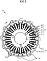
- FIG. 4 is a cross-sectional view of the permanent magnet type motor 20 shown in FIG. 2 , as sectioned perpendicular to its rotation axis line.
- the rotor 30 includes a permanent magnet part 37.
- the rotor 30 includes a plurality of magnetic pole portions 37a.
- the plurality of magnetic pole portions 37a are formed by the permanent magnet part 37.
- the plurality of magnetic pole portions 37a are provided on an inner circumferential surface of the back yoke portion 34.
- the permanent magnet part 37 includes a plurality of permanent magnets. That is, the rotor 30 includes a plurality of permanent magnets.
- the plurality of magnetic pole portions 37a are provided in the plurality of permanent magnets, respectively.
- the permanent magnet part 37 may alternatively be configured as a single annular permanent magnet.
- the single permanent magnet is magnetized such that the plurality of magnetic pole portions 37a appear side by side on the inner circumferential surface.
- the number of magnetic pole portions 37a included in the rotor 30 is more than the number of teeth 43.
- the number of magnetic pole portions is equal to 4/3 of the number of slots.
- the stator winding W is wound around each of the teeth 43. That is, the multi-phase stator windings W are arranged through the slots SL. In the state shown in FIG. 4 , the stator windings W are in the slots SL.
- Each of the multi-phase stator windings W belongs to any of U-phase, V-phase, and W-phase.
- the stator windings W are arranged in the order of U-phase, V-phase, and W-phase, for example.
- the rotor 30 includes, on its outer surface, a plurality of detection object parts 38 for detection of the rotation position of the rotor 30. Magnetic effects are used to detect the plurality of detection object parts 38.
- the plurality of detection object parts 38 arranged at intervals with respect to the circumferential direction are provided on the outer surface of the rotor 30.
- the detection object parts 38 are made of a ferromagnetic material.
- the combustion control unit 63 controls the spark plug 19 and the fuel injector device 18, to control the combustion operation of the single-cylinder engine 10.
- the combustion control unit 63 controls the spark plug 19 and the fuel injector device 18, to control the rotational force of the single-cylinder engine 10.
- the combustion control unit 63 controls the spark plug 19 and the fuel injector device 18 in accordance with the degree of opening of the throttle valve SV which is represented by an output signal of the throttle position sensor 80.
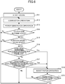
- the control device 60 determines that the condition regarding the amount of operation on the acceleration command part 8 is satisfied.
- step S19 the control device 60 determines whether or not an assistance termination condition regarding the piston operation is fulfilled. If the assistance termination condition is fulfilled (S19:Yes), the control device 60 terminates the assistance to the piston operation. If the assistance termination condition is not fulfilled (S19:No), the control device 60 continues the assistance to the piston operation (S18).
- the increased amount of mixed gas is combusted, so that the rotation speed of the crankshaft 15 significantly increases.
- the single-cylinder engine 10 is able to, after the rotation speed of the crankshaft 15 once rises, compress and combust an increased amount of air in a stable manner. As a result, power generated by the combustion operation which is a function inherent in the engine is increased like a chain reaction. The rotation speed of the crankshaft 15 rapidly increases accordingly.
Landscapes
- Engineering & Computer Science (AREA)
- Chemical & Material Sciences (AREA)
- Combustion & Propulsion (AREA)
- Mechanical Engineering (AREA)
- General Engineering & Computer Science (AREA)
- Power Engineering (AREA)
- Control Of Vehicle Engines Or Engines For Specific Uses (AREA)
- Control Of Throttle Valves Provided In The Intake System Or In The Exhaust System (AREA)
- Electrical Control Of Air Or Fuel Supplied To Internal-Combustion Engine (AREA)
Applications Claiming Priority (1)
| Application Number | Priority Date | Filing Date | Title |
|---|---|---|---|
| JP2016189636A JP2018053775A (ja) | 2016-09-28 | 2016-09-28 | 鞍乗型車両 |
Publications (2)
| Publication Number | Publication Date |
|---|---|
| EP3301280A1 true EP3301280A1 (fr) | 2018-04-04 |
| EP3301280B1 EP3301280B1 (fr) | 2020-03-04 |
Family
ID=60019674
Family Applications (1)
| Application Number | Title | Priority Date | Filing Date |
|---|---|---|---|
| EP17192000.2A Active EP3301280B1 (fr) | 2016-09-28 | 2017-09-20 | Véhicule à enfourcher |
Country Status (5)
| Country | Link |
|---|---|
| EP (1) | EP3301280B1 (fr) |
| JP (1) | JP2018053775A (fr) |
| MY (1) | MY186850A (fr) |
| PH (1) | PH12017050058A1 (fr) |
| TW (1) | TWI646008B (fr) |
Cited By (3)
| Publication number | Priority date | Publication date | Assignee | Title |
|---|---|---|---|---|
| CN111746695A (zh) * | 2019-03-29 | 2020-10-09 | 本田技研工业株式会社 | 跨骑式车辆 |
| CN111942365A (zh) * | 2019-05-17 | 2020-11-17 | 罗伯特·博世有限公司 | 用于运行由内燃机和电机构成的装置的方法 |
| EP3988412A4 (fr) * | 2019-07-24 | 2022-08-17 | Yamaha Hatsudoki Kabushiki Kaisha | Véhicule de type à enfourcher |
Citations (5)
| Publication number | Priority date | Publication date | Assignee | Title |
|---|---|---|---|---|
| US20030029653A1 (en) * | 2001-08-07 | 2003-02-13 | Jatco Ltd | Parallel hybrid vehicle |
| US20090050119A1 (en) * | 2006-03-28 | 2009-02-26 | Toyota Jidosha Kabushiki Kaisha | System and Method for Determining Acceleration of an Internal Combustion Engine |
| JP2013092097A (ja) * | 2011-10-25 | 2013-05-16 | Denso Corp | 始動発電機の制御装置 |
| JP2013253557A (ja) * | 2012-06-07 | 2013-12-19 | Mitsubishi Motors Corp | 内燃機関の制御装置 |
| EP3064748A1 (fr) * | 2013-12-20 | 2016-09-07 | Yamaha Hatsudoki Kabushiki Kaisha | Unité de moteur et véhicule |
Family Cites Families (3)
| Publication number | Priority date | Publication date | Assignee | Title |
|---|---|---|---|---|
| US9719429B2 (en) * | 2012-05-02 | 2017-08-01 | Cummins Ip, Inc. | Driver-assisted fuel reduction strategy and associated apparatus, system, and method |
| EP3064763A4 (fr) * | 2013-12-20 | 2017-03-08 | Yamaha Hatsudoki Kabushiki Kaisha | Unité de moteur et véhicule |
| JP2016070259A (ja) * | 2014-10-02 | 2016-05-09 | ヤマハ発動機株式会社 | エンジンシステムおよび鞍乗り型車両 |
-
2016
- 2016-09-28 JP JP2016189636A patent/JP2018053775A/ja active Pending
-
2017
- 2017-09-12 TW TW106131186A patent/TWI646008B/zh active
- 2017-09-20 EP EP17192000.2A patent/EP3301280B1/fr active Active
- 2017-09-26 MY MYPI2017703577A patent/MY186850A/en unknown
- 2017-09-27 PH PH12017050058A patent/PH12017050058A1/en unknown
Patent Citations (6)
| Publication number | Priority date | Publication date | Assignee | Title |
|---|---|---|---|---|
| US20030029653A1 (en) * | 2001-08-07 | 2003-02-13 | Jatco Ltd | Parallel hybrid vehicle |
| US20090050119A1 (en) * | 2006-03-28 | 2009-02-26 | Toyota Jidosha Kabushiki Kaisha | System and Method for Determining Acceleration of an Internal Combustion Engine |
| JP2013092097A (ja) * | 2011-10-25 | 2013-05-16 | Denso Corp | 始動発電機の制御装置 |
| JP5874315B2 (ja) | 2011-10-25 | 2016-03-02 | 株式会社デンソー | 始動発電機の制御装置 |
| JP2013253557A (ja) * | 2012-06-07 | 2013-12-19 | Mitsubishi Motors Corp | 内燃機関の制御装置 |
| EP3064748A1 (fr) * | 2013-12-20 | 2016-09-07 | Yamaha Hatsudoki Kabushiki Kaisha | Unité de moteur et véhicule |
Cited By (4)
| Publication number | Priority date | Publication date | Assignee | Title |
|---|---|---|---|---|
| CN111746695A (zh) * | 2019-03-29 | 2020-10-09 | 本田技研工业株式会社 | 跨骑式车辆 |
| CN111746695B (zh) * | 2019-03-29 | 2021-09-24 | 本田技研工业株式会社 | 跨骑式车辆 |
| CN111942365A (zh) * | 2019-05-17 | 2020-11-17 | 罗伯特·博世有限公司 | 用于运行由内燃机和电机构成的装置的方法 |
| EP3988412A4 (fr) * | 2019-07-24 | 2022-08-17 | Yamaha Hatsudoki Kabushiki Kaisha | Véhicule de type à enfourcher |
Also Published As
| Publication number | Publication date |
|---|---|
| PH12017050058B1 (en) | 2019-01-28 |
| TW201813862A (zh) | 2018-04-16 |
| JP2018053775A (ja) | 2018-04-05 |
| TWI646008B (zh) | 2019-01-01 |
| PH12017050058A1 (en) | 2019-01-28 |
| MY186850A (en) | 2021-08-26 |
| EP3301280B1 (fr) | 2020-03-04 |
Similar Documents
| Publication | Publication Date | Title |
|---|---|---|
| CN105849404B (zh) | 发动机单元和车辆 | |
| US20090020092A1 (en) | Engine starting device | |
| EP3051118B1 (fr) | Unité de moteur et véhicule | |
| TWI682863B (zh) | 車輛 | |
| EP3301280B1 (fr) | Véhicule à enfourcher | |
| US10293908B2 (en) | Outboard motor, engine starter, and engine starting method | |
| EP3306073B1 (fr) | Véhicule du type monté à califourchon | |
| TWI646257B (zh) | 引擎控制裝置、引擎單元及車輛 | |
| EP3332113A1 (fr) | Procédé pour gérer le redémarrage d'un moteur à combustion interne dans un système de démarrage et d'arrêt | |
| JP2017036666A (ja) | エンジンユニット | |
| EP3533993B1 (fr) | Procédé de commande d'une unité de moteur pour véhicule à enfourcher, unité de moteur et véhicule à enfourcher | |
| JP7258147B2 (ja) | ストラドルドビークル | |
| JP4066832B2 (ja) | 内燃機関の制御装置 | |
| CN105705771B (zh) | 发动机单元及车辆 | |
| JP2015117677A (ja) | エンジンユニット、及び車両 | |
| JP2017036665A (ja) | エンジンユニット | |
| JP2021080842A (ja) | エンジン始動制御装置 | |
| OA17770A (en) | Engine unit and vehicle | |
| JP2019161743A (ja) | 鞍乗型車両用エンジンユニットおよび鞍乗型車両 |
Legal Events
| Date | Code | Title | Description |
|---|---|---|---|
| PUAI | Public reference made under article 153(3) epc to a published international application that has entered the european phase |
Free format text: ORIGINAL CODE: 0009012 |
|
| STAA | Information on the status of an ep patent application or granted ep patent |
Free format text: STATUS: REQUEST FOR EXAMINATION WAS MADE |
|
| 17P | Request for examination filed |
Effective date: 20170920 |
|
| AK | Designated contracting states |
Kind code of ref document: A1 Designated state(s): AL AT BE BG CH CY CZ DE DK EE ES FI FR GB GR HR HU IE IS IT LI LT LU LV MC MK MT NL NO PL PT RO RS SE SI SK SM TR |
|
| AX | Request for extension of the european patent |
Extension state: BA ME |
|
| RBV | Designated contracting states (corrected) |
Designated state(s): AL AT BE BG CH CY CZ DE DK EE ES FI FR GB GR HR HU IE IS IT LI LT LU LV MC MK MT NL NO PL PT RO RS SE SI SK SM TR |
|
| STAA | Information on the status of an ep patent application or granted ep patent |
Free format text: STATUS: EXAMINATION IS IN PROGRESS |
|
| 17Q | First examination report despatched |
Effective date: 20181016 |
|
| GRAP | Despatch of communication of intention to grant a patent |
Free format text: ORIGINAL CODE: EPIDOSNIGR1 |
|
| STAA | Information on the status of an ep patent application or granted ep patent |
Free format text: STATUS: GRANT OF PATENT IS INTENDED |
|
| INTG | Intention to grant announced |
Effective date: 20191112 |
|
| RIN1 | Information on inventor provided before grant (corrected) |
Inventor name: NISHIKAWA, TAKAHIRO Inventor name: OBA, TATSUHIRO Inventor name: HINO, HARUYOSHI |
|
| GRAS | Grant fee paid |
Free format text: ORIGINAL CODE: EPIDOSNIGR3 |
|
| GRAA | (expected) grant |
Free format text: ORIGINAL CODE: 0009210 |
|
| STAA | Information on the status of an ep patent application or granted ep patent |
Free format text: STATUS: THE PATENT HAS BEEN GRANTED |
|
| AK | Designated contracting states |
Kind code of ref document: B1 Designated state(s): AL AT BE BG CH CY CZ DE DK EE ES FI FR GB GR HR HU IE IS IT LI LT LU LV MC MK MT NL NO PL PT RO RS SE SI SK SM TR |
|
| REG | Reference to a national code |
Ref country code: GB Ref legal event code: FG4D |
|
| REG | Reference to a national code |
Ref country code: CH Ref legal event code: EP |
|
| REG | Reference to a national code |
Ref country code: AT Ref legal event code: REF Ref document number: 1240638 Country of ref document: AT Kind code of ref document: T Effective date: 20200315 |
|
| REG | Reference to a national code |
Ref country code: DE Ref legal event code: R096 Ref document number: 602017012504 Country of ref document: DE |
|
| REG | Reference to a national code |
Ref country code: IE Ref legal event code: FG4D |
|
| PG25 | Lapsed in a contracting state [announced via postgrant information from national office to epo] |
Ref country code: RS Free format text: LAPSE BECAUSE OF FAILURE TO SUBMIT A TRANSLATION OF THE DESCRIPTION OR TO PAY THE FEE WITHIN THE PRESCRIBED TIME-LIMIT Effective date: 20200304 Ref country code: NO Free format text: LAPSE BECAUSE OF FAILURE TO SUBMIT A TRANSLATION OF THE DESCRIPTION OR TO PAY THE FEE WITHIN THE PRESCRIBED TIME-LIMIT Effective date: 20200604 Ref country code: FI Free format text: LAPSE BECAUSE OF FAILURE TO SUBMIT A TRANSLATION OF THE DESCRIPTION OR TO PAY THE FEE WITHIN THE PRESCRIBED TIME-LIMIT Effective date: 20200304 |
|
| REG | Reference to a national code |
Ref country code: NL Ref legal event code: MP Effective date: 20200304 |
|
| PG25 | Lapsed in a contracting state [announced via postgrant information from national office to epo] |
Ref country code: LV Free format text: LAPSE BECAUSE OF FAILURE TO SUBMIT A TRANSLATION OF THE DESCRIPTION OR TO PAY THE FEE WITHIN THE PRESCRIBED TIME-LIMIT Effective date: 20200304 Ref country code: SE Free format text: LAPSE BECAUSE OF FAILURE TO SUBMIT A TRANSLATION OF THE DESCRIPTION OR TO PAY THE FEE WITHIN THE PRESCRIBED TIME-LIMIT Effective date: 20200304 Ref country code: BG Free format text: LAPSE BECAUSE OF FAILURE TO SUBMIT A TRANSLATION OF THE DESCRIPTION OR TO PAY THE FEE WITHIN THE PRESCRIBED TIME-LIMIT Effective date: 20200604 Ref country code: GR Free format text: LAPSE BECAUSE OF FAILURE TO SUBMIT A TRANSLATION OF THE DESCRIPTION OR TO PAY THE FEE WITHIN THE PRESCRIBED TIME-LIMIT Effective date: 20200605 Ref country code: HR Free format text: LAPSE BECAUSE OF FAILURE TO SUBMIT A TRANSLATION OF THE DESCRIPTION OR TO PAY THE FEE WITHIN THE PRESCRIBED TIME-LIMIT Effective date: 20200304 |
|
| REG | Reference to a national code |
Ref country code: LT Ref legal event code: MG4D |
|
| PG25 | Lapsed in a contracting state [announced via postgrant information from national office to epo] |
Ref country code: NL Free format text: LAPSE BECAUSE OF FAILURE TO SUBMIT A TRANSLATION OF THE DESCRIPTION OR TO PAY THE FEE WITHIN THE PRESCRIBED TIME-LIMIT Effective date: 20200304 |
|
| PG25 | Lapsed in a contracting state [announced via postgrant information from national office to epo] |
Ref country code: RO Free format text: LAPSE BECAUSE OF FAILURE TO SUBMIT A TRANSLATION OF THE DESCRIPTION OR TO PAY THE FEE WITHIN THE PRESCRIBED TIME-LIMIT Effective date: 20200304 Ref country code: IS Free format text: LAPSE BECAUSE OF FAILURE TO SUBMIT A TRANSLATION OF THE DESCRIPTION OR TO PAY THE FEE WITHIN THE PRESCRIBED TIME-LIMIT Effective date: 20200704 Ref country code: SK Free format text: LAPSE BECAUSE OF FAILURE TO SUBMIT A TRANSLATION OF THE DESCRIPTION OR TO PAY THE FEE WITHIN THE PRESCRIBED TIME-LIMIT Effective date: 20200304 Ref country code: EE Free format text: LAPSE BECAUSE OF FAILURE TO SUBMIT A TRANSLATION OF THE DESCRIPTION OR TO PAY THE FEE WITHIN THE PRESCRIBED TIME-LIMIT Effective date: 20200304 Ref country code: PT Free format text: LAPSE BECAUSE OF FAILURE TO SUBMIT A TRANSLATION OF THE DESCRIPTION OR TO PAY THE FEE WITHIN THE PRESCRIBED TIME-LIMIT Effective date: 20200729 Ref country code: SM Free format text: LAPSE BECAUSE OF FAILURE TO SUBMIT A TRANSLATION OF THE DESCRIPTION OR TO PAY THE FEE WITHIN THE PRESCRIBED TIME-LIMIT Effective date: 20200304 Ref country code: LT Free format text: LAPSE BECAUSE OF FAILURE TO SUBMIT A TRANSLATION OF THE DESCRIPTION OR TO PAY THE FEE WITHIN THE PRESCRIBED TIME-LIMIT Effective date: 20200304 Ref country code: ES Free format text: LAPSE BECAUSE OF FAILURE TO SUBMIT A TRANSLATION OF THE DESCRIPTION OR TO PAY THE FEE WITHIN THE PRESCRIBED TIME-LIMIT Effective date: 20200304 Ref country code: CZ Free format text: LAPSE BECAUSE OF FAILURE TO SUBMIT A TRANSLATION OF THE DESCRIPTION OR TO PAY THE FEE WITHIN THE PRESCRIBED TIME-LIMIT Effective date: 20200304 |
|
| REG | Reference to a national code |
Ref country code: AT Ref legal event code: MK05 Ref document number: 1240638 Country of ref document: AT Kind code of ref document: T Effective date: 20200304 |
|
| REG | Reference to a national code |
Ref country code: DE Ref legal event code: R097 Ref document number: 602017012504 Country of ref document: DE |
|
| PLBE | No opposition filed within time limit |
Free format text: ORIGINAL CODE: 0009261 |
|
| STAA | Information on the status of an ep patent application or granted ep patent |
Free format text: STATUS: NO OPPOSITION FILED WITHIN TIME LIMIT |
|
| PG25 | Lapsed in a contracting state [announced via postgrant information from national office to epo] |
Ref country code: AT Free format text: LAPSE BECAUSE OF FAILURE TO SUBMIT A TRANSLATION OF THE DESCRIPTION OR TO PAY THE FEE WITHIN THE PRESCRIBED TIME-LIMIT Effective date: 20200304 Ref country code: DK Free format text: LAPSE BECAUSE OF FAILURE TO SUBMIT A TRANSLATION OF THE DESCRIPTION OR TO PAY THE FEE WITHIN THE PRESCRIBED TIME-LIMIT Effective date: 20200304 |
|
| 26N | No opposition filed |
Effective date: 20201207 |
|
| PG25 | Lapsed in a contracting state [announced via postgrant information from national office to epo] |
Ref country code: PL Free format text: LAPSE BECAUSE OF FAILURE TO SUBMIT A TRANSLATION OF THE DESCRIPTION OR TO PAY THE FEE WITHIN THE PRESCRIBED TIME-LIMIT Effective date: 20200304 Ref country code: SI Free format text: LAPSE BECAUSE OF FAILURE TO SUBMIT A TRANSLATION OF THE DESCRIPTION OR TO PAY THE FEE WITHIN THE PRESCRIBED TIME-LIMIT Effective date: 20200304 |
|
| REG | Reference to a national code |
Ref country code: CH Ref legal event code: PL |
|
| REG | Reference to a national code |
Ref country code: BE Ref legal event code: MM Effective date: 20200930 |
|
| PG25 | Lapsed in a contracting state [announced via postgrant information from national office to epo] |
Ref country code: LU Free format text: LAPSE BECAUSE OF NON-PAYMENT OF DUE FEES Effective date: 20200920 |
|
| PG25 | Lapsed in a contracting state [announced via postgrant information from national office to epo] |
Ref country code: BE Free format text: LAPSE BECAUSE OF NON-PAYMENT OF DUE FEES Effective date: 20200930 Ref country code: CH Free format text: LAPSE BECAUSE OF NON-PAYMENT OF DUE FEES Effective date: 20200930 Ref country code: LI Free format text: LAPSE BECAUSE OF NON-PAYMENT OF DUE FEES Effective date: 20200930 Ref country code: IE Free format text: LAPSE BECAUSE OF NON-PAYMENT OF DUE FEES Effective date: 20200920 |
|
| GBPC | Gb: european patent ceased through non-payment of renewal fee |
Effective date: 20210920 |
|
| PG25 | Lapsed in a contracting state [announced via postgrant information from national office to epo] |
Ref country code: TR Free format text: LAPSE BECAUSE OF FAILURE TO SUBMIT A TRANSLATION OF THE DESCRIPTION OR TO PAY THE FEE WITHIN THE PRESCRIBED TIME-LIMIT Effective date: 20200304 Ref country code: MT Free format text: LAPSE BECAUSE OF FAILURE TO SUBMIT A TRANSLATION OF THE DESCRIPTION OR TO PAY THE FEE WITHIN THE PRESCRIBED TIME-LIMIT Effective date: 20200304 Ref country code: CY Free format text: LAPSE BECAUSE OF FAILURE TO SUBMIT A TRANSLATION OF THE DESCRIPTION OR TO PAY THE FEE WITHIN THE PRESCRIBED TIME-LIMIT Effective date: 20200304 |
|
| PG25 | Lapsed in a contracting state [announced via postgrant information from national office to epo] |
Ref country code: MK Free format text: LAPSE BECAUSE OF FAILURE TO SUBMIT A TRANSLATION OF THE DESCRIPTION OR TO PAY THE FEE WITHIN THE PRESCRIBED TIME-LIMIT Effective date: 20200304 Ref country code: MC Free format text: LAPSE BECAUSE OF FAILURE TO SUBMIT A TRANSLATION OF THE DESCRIPTION OR TO PAY THE FEE WITHIN THE PRESCRIBED TIME-LIMIT Effective date: 20200304 Ref country code: AL Free format text: LAPSE BECAUSE OF FAILURE TO SUBMIT A TRANSLATION OF THE DESCRIPTION OR TO PAY THE FEE WITHIN THE PRESCRIBED TIME-LIMIT Effective date: 20200304 |
|
| PG25 | Lapsed in a contracting state [announced via postgrant information from national office to epo] |
Ref country code: GB Free format text: LAPSE BECAUSE OF NON-PAYMENT OF DUE FEES Effective date: 20210920 |
|
| P01 | Opt-out of the competence of the unified patent court (upc) registered |
Effective date: 20230527 |
|
| PGFP | Annual fee paid to national office [announced via postgrant information from national office to epo] |
Ref country code: IT Payment date: 20240924 Year of fee payment: 8 |
|
| PGFP | Annual fee paid to national office [announced via postgrant information from national office to epo] |
Ref country code: DE Payment date: 20250919 Year of fee payment: 9 |
|
| PGFP | Annual fee paid to national office [announced via postgrant information from national office to epo] |
Ref country code: FR Payment date: 20250922 Year of fee payment: 9 |