EP3301304A2 - Buse d'aspiration et unité de soufflage d'un ventilateur - Google Patents
Buse d'aspiration et unité de soufflage d'un ventilateur Download PDFInfo
- Publication number
- EP3301304A2 EP3301304A2 EP17188455.4A EP17188455A EP3301304A2 EP 3301304 A2 EP3301304 A2 EP 3301304A2 EP 17188455 A EP17188455 A EP 17188455A EP 3301304 A2 EP3301304 A2 EP 3301304A2
- Authority
- EP
- European Patent Office
- Prior art keywords
- flow
- bypass
- fan
- suction nozzle
- housing
- Prior art date
- Legal status (The legal status is an assumption and is not a legal conclusion. Google has not performed a legal analysis and makes no representation as to the accuracy of the status listed.)
- Granted
Links
Images





Classifications
-
- F—MECHANICAL ENGINEERING; LIGHTING; HEATING; WEAPONS; BLASTING
- F04—POSITIVE - DISPLACEMENT MACHINES FOR LIQUIDS; PUMPS FOR LIQUIDS OR ELASTIC FLUIDS
- F04D—NON-POSITIVE-DISPLACEMENT PUMPS
- F04D29/00—Details, component parts, or accessories
- F04D29/70—Suction grids; Strainers; Dust separation; Cleaning
- F04D29/701—Suction grids; Strainers; Dust separation; Cleaning especially adapted for elastic fluid pumps
- F04D29/703—Suction grids; Strainers; Dust separation; Cleaning especially adapted for elastic fluid pumps specially for fans, e.g. fan guards
-
- F—MECHANICAL ENGINEERING; LIGHTING; HEATING; WEAPONS; BLASTING
- F04—POSITIVE - DISPLACEMENT MACHINES FOR LIQUIDS; PUMPS FOR LIQUIDS OR ELASTIC FLUIDS
- F04D—NON-POSITIVE-DISPLACEMENT PUMPS
- F04D17/00—Radial-flow pumps, e.g. centrifugal pumps; Helico-centrifugal pumps
- F04D17/08—Centrifugal pumps
- F04D17/16—Centrifugal pumps for displacing without appreciable compression
-
- F—MECHANICAL ENGINEERING; LIGHTING; HEATING; WEAPONS; BLASTING
- F04—POSITIVE - DISPLACEMENT MACHINES FOR LIQUIDS; PUMPS FOR LIQUIDS OR ELASTIC FLUIDS
- F04D—NON-POSITIVE-DISPLACEMENT PUMPS
- F04D19/00—Axial-flow pumps
- F04D19/002—Axial flow fans
-
- F—MECHANICAL ENGINEERING; LIGHTING; HEATING; WEAPONS; BLASTING
- F04—POSITIVE - DISPLACEMENT MACHINES FOR LIQUIDS; PUMPS FOR LIQUIDS OR ELASTIC FLUIDS
- F04D—NON-POSITIVE-DISPLACEMENT PUMPS
- F04D27/00—Control, e.g. regulation, of pumps, pumping installations or pumping systems specially adapted for elastic fluids
- F04D27/001—Testing thereof; Determination or simulation of flow characteristics; Stall or surge detection, e.g. condition monitoring
-
- F—MECHANICAL ENGINEERING; LIGHTING; HEATING; WEAPONS; BLASTING
- F04—POSITIVE - DISPLACEMENT MACHINES FOR LIQUIDS; PUMPS FOR LIQUIDS OR ELASTIC FLUIDS
- F04D—NON-POSITIVE-DISPLACEMENT PUMPS
- F04D29/00—Details, component parts, or accessories
- F04D29/40—Casings; Connections of working fluid
- F04D29/42—Casings; Connections of working fluid for radial or helico-centrifugal pumps
- F04D29/4206—Casings; Connections of working fluid for radial or helico-centrifugal pumps especially adapted for elastic fluid pumps
- F04D29/4226—Fan casings
-
- F—MECHANICAL ENGINEERING; LIGHTING; HEATING; WEAPONS; BLASTING
- F04—POSITIVE - DISPLACEMENT MACHINES FOR LIQUIDS; PUMPS FOR LIQUIDS OR ELASTIC FLUIDS
- F04D—NON-POSITIVE-DISPLACEMENT PUMPS
- F04D29/00—Details, component parts, or accessories
- F04D29/40—Casings; Connections of working fluid
- F04D29/42—Casings; Connections of working fluid for radial or helico-centrifugal pumps
- F04D29/4206—Casings; Connections of working fluid for radial or helico-centrifugal pumps especially adapted for elastic fluid pumps
- F04D29/4226—Fan casings
- F04D29/4253—Fan casings with axial entry and discharge
-
- G—PHYSICS
- G01—MEASURING; TESTING
- G01F—MEASURING VOLUME, VOLUME FLOW, MASS FLOW OR LIQUID LEVEL; METERING BY VOLUME
- G01F1/00—Measuring the volume flow or mass flow of fluid or fluent solid material wherein the fluid passes through a meter in a continuous flow
- G01F1/05—Measuring the volume flow or mass flow of fluid or fluent solid material wherein the fluid passes through a meter in a continuous flow by using mechanical effects
-
- G—PHYSICS
- G01—MEASURING; TESTING
- G01F—MEASURING VOLUME, VOLUME FLOW, MASS FLOW OR LIQUID LEVEL; METERING BY VOLUME
- G01F1/00—Measuring the volume flow or mass flow of fluid or fluent solid material wherein the fluid passes through a meter in a continuous flow
- G01F1/68—Measuring the volume flow or mass flow of fluid or fluent solid material wherein the fluid passes through a meter in a continuous flow by using thermal effects
- G01F1/684—Structural arrangements; Mounting of elements, e.g. in relation to fluid flow
- G01F1/688—Structural arrangements; Mounting of elements, e.g. in relation to fluid flow using a particular type of heating, cooling or sensing element
- G01F1/69—Structural arrangements; Mounting of elements, e.g. in relation to fluid flow using a particular type of heating, cooling or sensing element of resistive type
- G01F1/692—Thin-film arrangements
-
- G—PHYSICS
- G01—MEASURING; TESTING
- G01F—MEASURING VOLUME, VOLUME FLOW, MASS FLOW OR LIQUID LEVEL; METERING BY VOLUME
- G01F5/00—Measuring a proportion of the volume flow
-
- F—MECHANICAL ENGINEERING; LIGHTING; HEATING; WEAPONS; BLASTING
- F05—INDEXING SCHEMES RELATING TO ENGINES OR PUMPS IN VARIOUS SUBCLASSES OF CLASSES F01-F04
- F05D—INDEXING SCHEME FOR ASPECTS RELATING TO NON-POSITIVE-DISPLACEMENT MACHINES OR ENGINES, GAS-TURBINES OR JET-PROPULSION PLANTS
- F05D2270/00—Control
- F05D2270/30—Control parameters, e.g. input parameters
- F05D2270/301—Pressure
- F05D2270/3015—Pressure differential pressure
Definitions
- the invention relates to a suction nozzle and a blow-out of a fan with integrated volume flow measurement and the fan.
- drum fans have been used in air conditioning and air conditioning because they are characterized by a good noise behavior even under disturbed inflow conditions.
- Volume flow determination is possible with drum-type fans by a clear relationship between power consumption and volume flow at constant speed.
- the disadvantage is that compared to Centrifugal fans, especially with fan blades with backward curved blades, relatively low efficiency.
- the invention has for its object to integrate a solution for a flow measurement on an existing fan, which has the smallest possible error or tolerance-biased deviation, even at low flow rates.
- the invention is based on integrating the volume flow measurement into the intake nozzle or the blow-out unit of a fan, in particular an axial fan. Also, a volumetric flow measurement in both the suction nozzle and the blow-out unit is possible, for example to determine an average or deviation value from the two measurement results.
- a suction nozzle for a fan with a suction opening for sucking a main fan flow is proposed.
- the suction nozzle has an opening edge section adjoining the suction opening with at least one local outbreak into which a flow insert can be detachably fastened.
- the flow insert forms a bypass opening into the intake opening for a bypass flow which opens into the fan main flow.
- corresponding measuring means or sensors for measuring the volume flow are arranged in the bypass.
- hot-filament manometry is preferably used, for which evaluation electronics and two sensors in the form of thermocouples are necessary.
- sensors an ambient temperature measuring PT100 and PT1000 thermocouple are used, which are mounted on the surface of a board or the printed circuit board so that they lie in the bypass flow.
- the PT100 is mounted on the circuit board, the PT1000 as a PTC with terminal clips directly on the PCB of the sensor to position the resistors in a flow line of the bypass flow and thereby increase the measurement accuracy.
- About the locking hooks a position-fixed attachment of the measuring device in the bypass is possible.
- the flow insert has a shape or outer contour that corresponds to a shape of the shape adjacent to the breakout Opening edge portion corresponds, so that the opening edge portion is formed continuously with attached flow insert. This means that the opening edge portion is formed without interruption with secure flow insert in the outbreak, as if no outbreak was provided. The flow insert fills the outbreak completely in the inserted state.
- the flow insert in the bypass has a confuser, via which the bypass flow is accelerated and bundled.
- the measuring means are arranged in the narrowest flow cross-section of the confuser after an inlet section of the confuser, which corresponds to a 3-5 times the width of the nozzle channel formed by the confuser.
- an optimal flow of the measuring means or sensors can be realized.
- an increase in the total velocity of the bypass flow is achieved by the confuser. This advantage is particularly relevant in operating areas of the fan in which only low speeds are required or the fan is in power-up.
- the increase in the flow velocity in the confuser thus also ensures in regions with low flow velocity for an increased flow velocity of the measuring means or sensors. A meaningful measurement result is thus guaranteed across all operating points of the fan.
- the confuser is integrally formed on the flow insert.
- This solution is achieved, for example, in that the confuser is formed by mutually facing webs, which form a nozzle channel in the bypass.
- the shape and extent of the webs is readily adaptable to match the geometry of the flow insert and to ensure the desired nozzle shape of the confuser.
- Flow insert for a positionally fixed attachment of the measuring means in the nozzle channel has the Flow insert in a favorable embodiment locking elements, such as latching hooks for clipping the flow element at the opening edge portion of the suction nozzle.
- the flow insert has an axial inlet opening extending at a radial outer edge of the flow insert and an axial outlet opening extending at a radial inner edge of the flow insert, so that the bypass flow sucked axially and axially into the main fan flow is returned.
- the inlet opening is located radially at the outer edge of the flow insert, the outlet opening at its radial inner edge, which forms a part of the suction opening over the length of the outbreak.
- the flow insert has an inlet section extending in the axial direction, to which the axial outlet opening adjoins.
- the inlet section forms a contour which allows an axial supply of the bypass flow into the main fan flow.
- the bypass itself runs along the opening edge portion and in particular substantially perpendicular or perpendicular to the axial direction of the main fan flow.
- the vertical course corresponds to the radial direction.
- a positive geometric configuration is shown in the suction nozzle when the breakout and the flow insert extend over 10 - 30% of a total length of the edge of the suction port.
- the suction opening of the suction nozzle of a fan is round, so that the breakout and the flow insert preferably extend over 10 - 30% of the circumferential length of the suction opening.
- the invention further includes the blower unit of the fan which is used for Recording the fan wheel is formed.
- the blow-out unit comprises a housing part which immediately adjoins the ventilator wheel in the direction of use and which can flow against the fan main flow and which forms a housing bypass for a bypass flow of the main ventilator flow.
- the housing bypass measuring means or a sensor for flow determination of the main fan flow are arranged. The measuring means or sensors used correspond to those described above.
- the outlet-side volumetric flow measurement is further improved in a design variant in which the housing bypass has a housing confuser and the measuring means for volume flow measurement of the main fan flow are arranged in a narrowest flow cross-section of the housing confuser.
- the confuser accelerates and bundles the bypass flow.
- the housing confuser is generated by webs facing one another, which form a housing nozzle channel in the housing bypass.
- An inflow-side opening angle formed by the webs of the Gesimousekonfusors is in an advantageous embodiment in a range of 90 - 110 °.
- an embodiment is advantageous in which a flow rectifier for the bypass flow is arranged inside the housing bypass upstream of the measuring device for determining the volume flow.
- the flow straightener provides conditioning and laminarization of the flow, eliminating turbulence, swirling effects and profile displacements due to the confuser and turbulent exhaust field. This is a measurable improvement in the accuracy of the flow measurement on the fan to achieve.
- a distance E in the flow direction between the Strömungsgelichrichter and the measuring means in relation to a bypass width D in the range of the measuring means is set such that 0.5 * D ⁇ E ⁇ 1.5 * D.
- the flow straightener is a honeycomb rectifier. Although this must be dimensioned longer in the flow direction, but also provides better rectification effects.
- an outflow section F between the measuring means and an outermost exit point of the bypass flow is set relative to a bypass width D in the region of the measuring means such that 1.5 * D ⁇ F ⁇ 2 * D
- the straight inlet section B of the bypass flow within the housing part up to the flow rectifier is advantageously set in relation to a bypass width D in the region of the measuring means such that 3 * D ⁇ B ⁇ 5 * D.
- the blow-out unit is favorably characterized in that the housing part is designed as a cable receptacle for a connection cable of the fan and the housing bypass is integrated in the cable receptacle.
- the cable receptacle which can be formed in the art as a cable protection strut with integrable capacitor holder, is usually positioned at the intended position for the housing part near the blow-out of the fan wheel and is therefore suitable as the bypass housing forming housing part.
- the invention further comprises the entire fan with a suction nozzle as described above, a blow-out unit and a fan wheel arranged between the suction nozzle and the blow-out unit.
- the suction nozzle and the blow-out unit are connected via mounting legs and surround the fan wheel, which in operation, the main fan flow and the bypass flow generated by the bypass of the suction nozzle.
- the invention comprises the fan with a suction nozzle, a blow-out unit as described above and a fan wheel arranged between the suction nozzle and the blow-out unit.
- the suction nozzle and the blow-out unit are connected via attachment legs and surround the fan wheel, which in operation generates the fan main flow as well as the bypass flow through the housing bypass of the housing part of the blow-out unit.
- the fan comprises both the above-described suction nozzle and the above-described blow-out unit and thus a redundant volume flow measurement.
- FIG. 1 the fan 1 is shown in a perspective view with a suction nozzle 2, a blow-out unit 3 and a motor-driven fan wheel 5 between them.
- the suction nozzle 2 is plate-shaped and has centrally a round radially and axially retracted suction opening 8.
- the blow-out unit 3 is formed from a bottom plate 13 receiving the fan wheel 5 with a housing part 4 attached thereto and designed as a cable receiver.
- the suction nozzle 2 and the blow-out unit 3 are connected via four legs 6 provided in the corners, so that the fan 1 constitutes a structural unit ,
- the legs 6 are partly formed on the suction nozzle 2 partly on the bottom plate or the housing part 4 and lock into each other.
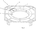
- FIG. 2 the suction nozzle 2 is shown individually and in more detail.
- FIG. 2 which in the subsequent to the intake opening 8 or determining this opening edge portion 7 is shown with a local outbreak 11.
- the body of the suction nozzle 2 runs to the suction opening 8, but a free space for the flow insert 10 is provided, which completely filled the opening 11 in the inserted state, so that the opening edge portion 7 extends continuously in the circumferential direction and radial direction.
- the flow insert 10 has a shape that corresponds to the shape of the opening edge section 7 adjoining the breakout 11.
- the gap at the edge of the flow insert 10 is fluidly negligible. to releasable attachment of the flow insert 10 in the outbreak 11 suitable Einclips- or latching elements are provided.
- the flow insert 10 is shown in more detail from both sides.
- the flow insert 10 has an axial inlet opening 21 extending at its radial outer edge and an axial outlet opening 22 extending at the radial inner edge, and forms the bypass for the bypass flow therebetween.
- the bypass flow is drawn in axially, extends radially through the flow insert 10 and is returned via the substantially axially aligned outlet opening 22 into the main fan flow at the intake opening 8.
- each other webs 24, 25 are formed, which produce a Konfusor with a nozzle channel 26, through which the bypass flow is urged.
- the webs 24, 25 form a closed contour and thus guide the bypass flow exclusively through the nozzle channel 26th
- the nozzle channel 26 formed by the webs 24, 25 extends in a straight line radially outward.
- the measuring means or sensor 30 is arranged, the inlet section B being three times as long as the nozzle channel width C.
- the outlet section extending from the sensor 30 to the suction opening is twice as large as the nozzle width C.
- the nozzle channel has a constant nozzle channel width B in the region of the sensor 30. With D2, the diameter of the suction port 8 and D1 of the diameter at the inlet port 21 is indicated.
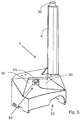
- FIG. 5 shows the housing part 4 from FIG. 1 formed as a cable receptacle of the fan 1.
- the housing part 4 forms the housing bypass for the bypass flow of the main fan flow in the blow-out unit 3, wherein in the housing bypass, the measuring means or sensors for volume flow determination of the main fan flow are arranged, as in Fig. 7 shown in more detail.
- the leg 6 is integrally formed with a connection head 36, via which the leg 6 is connected to the suction nozzle 2.
- the housing part 4 has in the lower portion a recess 33 for the introduction of the fan connection cable (not shown).
- other components, not shown, such as a capacitor holder can be integrated into the housing part 4.
- injection opening 43 is provided in the housing part 4, which provides the entrance or beginning of the formed by the webs 34 and 35 housing bypass.
- a honeycomb rectifier 44 for conditioning and laminarization of the injected air flow upstream of the measuring means for volume flow measurement is integrated.
- FIGS. 6a, 6b and 7 the housing part 4 and the housing bypass formed therein is shown in more detail.
- Fig. 7 A detailed view A of the sectional view AA Fig. 6b , the closed shape of the webs 34, 35 is clearly visible, which generates the nozzle channel 36.
- the web 35 which is blown directly by the fan wheel 5, runs essentially perpendicular to the direction of discharge, the web 35 forms a rounding at the injection opening 43 as a transition into the nozzle channel 36 of the housing bypass.
- Both webs 34, 35 introduce the flow into the nozzle channel 36 and form the Gepurusekonfusor, in which both the honeycomb rectifier 44 and the measuring means 30 are arranged for measuring the volume flow.
- the honeycomb rectifier 44 flatly covers the entire nozzle channel 36.
- the inflow-side opening angle ⁇ of the housing confuser formed by the webs 34, 35 is 95 ° in the illustrated embodiment.
- the measuring means 30 are arranged by the honeycomb rectifier 44 at a distance E corresponding to half of the bypass width D.
- the inlet section B is determined by the length of the web 34 to the honeycomb rectifier 44 and corresponds to four times the bypass width D in the illustrated embodiment.
- the discharge path F is determined between the measuring means 30 and the outermost exit point of the bypass flow at the edge of the web 35 and corresponds in the embodiment shown in FIG 5 times the bypass width D.
- the width C of the honeycomb rectifier 44 is preferably in a range of 0.7-1.0 of the bypass width D, and is 0.8 * D in the illustrated embodiment.
- the bypass width D corresponds to the width of the sectionally parallel extending webs 34, 35 rectilinearly with a constant width extending nozzle channel 36th
Landscapes
- Engineering & Computer Science (AREA)
- Mechanical Engineering (AREA)
- General Engineering & Computer Science (AREA)
- Physics & Mathematics (AREA)
- Fluid Mechanics (AREA)
- General Physics & Mathematics (AREA)
- Structures Of Non-Positive Displacement Pumps (AREA)
- Measuring Volume Flow (AREA)
- Spinning Or Twisting Of Yarns (AREA)
- External Artificial Organs (AREA)
- Jet Pumps And Other Pumps (AREA)
Priority Applications (1)
| Application Number | Priority Date | Filing Date | Title |
|---|---|---|---|
| EP18163059.1A EP3358194B1 (fr) | 2016-09-28 | 2017-08-30 | Unité de purge d'un ventilateur |
Applications Claiming Priority (1)
| Application Number | Priority Date | Filing Date | Title |
|---|---|---|---|
| DE102016118369.5A DE102016118369A1 (de) | 2016-09-28 | 2016-09-28 | Ansaugdüse und Ausblaseinheit eines Ventilators |
Related Child Applications (2)
| Application Number | Title | Priority Date | Filing Date |
|---|---|---|---|
| EP18163059.1A Division-Into EP3358194B1 (fr) | 2016-09-28 | 2017-08-30 | Unité de purge d'un ventilateur |
| EP18163059.1A Division EP3358194B1 (fr) | 2016-09-28 | 2017-08-30 | Unité de purge d'un ventilateur |
Publications (3)
| Publication Number | Publication Date |
|---|---|
| EP3301304A2 true EP3301304A2 (fr) | 2018-04-04 |
| EP3301304A3 EP3301304A3 (fr) | 2018-06-13 |
| EP3301304B1 EP3301304B1 (fr) | 2022-08-17 |
Family
ID=59349287
Family Applications (2)
| Application Number | Title | Priority Date | Filing Date |
|---|---|---|---|
| EP17188455.4A Active EP3301304B1 (fr) | 2016-09-28 | 2017-08-30 | Buse d'aspiration et unité de soufflage d'un ventilateur |
| EP18163059.1A Active EP3358194B1 (fr) | 2016-09-28 | 2017-08-30 | Unité de purge d'un ventilateur |
Family Applications After (1)
| Application Number | Title | Priority Date | Filing Date |
|---|---|---|---|
| EP18163059.1A Active EP3358194B1 (fr) | 2016-09-28 | 2017-08-30 | Unité de purge d'un ventilateur |
Country Status (4)
| Country | Link |
|---|---|
| US (1) | US10550856B2 (fr) |
| EP (2) | EP3301304B1 (fr) |
| CN (1) | CN206352594U (fr) |
| DE (1) | DE102016118369A1 (fr) |
Cited By (1)
| Publication number | Priority date | Publication date | Assignee | Title |
|---|---|---|---|---|
| WO2019063395A1 (fr) * | 2017-09-26 | 2019-04-04 | Ebm-Papst Mulfingen Gmbh & Co. Kg | Ventilateur radial doté d'une mesure de pression différentielle |
Families Citing this family (4)
| Publication number | Priority date | Publication date | Assignee | Title |
|---|---|---|---|---|
| DE102018105063A1 (de) | 2018-03-06 | 2019-09-12 | Ebm-Papst Mulfingen Gmbh & Co. Kg | Vorrichtung und Verfahren zur Luftmengenerfassung |
| DE102018211808A1 (de) * | 2018-07-16 | 2020-01-16 | Ziehl-Abegg Se | Ventilator und Leiteinrichtung für einen Ventilator |
| DE102020200363A1 (de) * | 2020-01-14 | 2021-07-15 | Ziehl-Abegg Se | Tragmodul für einen Ventilator und Ventilator mit einem entsprechenden Tragmodul |
| DE102024207656A1 (de) * | 2024-08-12 | 2026-02-12 | Ziehl-Abegg Se | Einströmdüse für einen Radial-, Diagonal- oder Axialventilator und Radial-, Diagonal- oder Axialventilator mit Einströmdüse |
Family Cites Families (20)
| Publication number | Priority date | Publication date | Assignee | Title |
|---|---|---|---|---|
| JPS59131116A (ja) * | 1983-01-17 | 1984-07-27 | Nippon Furooseru Kk | 送風機 |
| FI81447C (fi) * | 1987-09-15 | 1990-10-10 | Ilmaterae Oy | Anordning foer uppmaetning av volymstroem i blaester. |
| DE8911433U1 (de) * | 1989-09-26 | 1989-11-23 | Gebhardt Ventilatoren GmbH & Co, 7112 Waldenburg | Vorrichtung zur Bestimmung des Volumenstroms eines Radialventilators |
| DE69204861T2 (de) | 1991-01-30 | 1996-05-23 | United Technologies Corp | Ventilatorgehäuse mit Rezirculationskanälen. |
| SE500539C2 (sv) * | 1991-06-12 | 1994-07-11 | Flaekt Ab | Sätt och anordning för bestämning av genomströmningsflödet i en ventilationsanläggning med en frisugande fläkt |
| CA2123640A1 (fr) * | 1993-05-17 | 1994-11-18 | Thomas A. Berger | Ventilateur centrifuge a debitmetre |
| DE9416448U1 (de) | 1994-10-13 | 1994-12-01 | Maico Elektroapparate-Fabrik Gmbh, 78056 Villingen-Schwenningen | Ventilator mit Feuchtesensor in natürlicher Luftströmung |
| DE19629220B4 (de) * | 1996-07-19 | 2005-05-12 | Motoren Ventilatoren Landshut Gmbh | Hochdruck-Gebläse |
| DE19726547A1 (de) * | 1997-06-23 | 1999-01-28 | Babcock Bsh Gmbh | Verfahren zur Bestimmung des Betriebspunktes eines Ventilators und Ventilator |
| DE10114405B4 (de) * | 2001-03-23 | 2011-03-24 | Ebm-Papst Landshut Gmbh | Gebläse für Verbrennungsluft |
| DE10256962A1 (de) * | 2002-12-05 | 2004-07-08 | Stego-Holding Gmbh | Lüfter |
| US9120043B2 (en) * | 2006-05-30 | 2015-09-01 | 3M Innovative Properties Company | Filter sensor |
| ITPD20060078U1 (it) * | 2006-06-07 | 2007-12-08 | Ln 2 Srl A Socio Unico | Dispositivo di spporto per sensori di pressione disposti internamente alle camere di pressione di ventilatori centrifughi particolarmente per cappe aspiranti o estrattori di fumi |
| US20080034753A1 (en) | 2006-08-15 | 2008-02-14 | Anthony Holmes Furman | Turbocharger Systems and Methods for Operating the Same |
| NZ597256A (en) * | 2009-08-11 | 2013-11-29 | Resmed Motor Technologies Inc | Single stage, axial symmetric blower and portable ventilator |
| CA2840594C (fr) * | 2011-07-13 | 2020-03-10 | Fisher & Paykel Healthcare Limited | Ensemble rotor et moteur |
| DE102015000629A1 (de) | 2015-01-22 | 2016-07-28 | Viessmann Werke Gmbh & Co Kg | Turboverdichter |
| EP3048429B1 (fr) | 2015-01-26 | 2020-08-26 | Sensirion AG | Dispositif pour mesurer un flux principal de fluide à travers une installation de ventilation |
| DE102015109684B3 (de) * | 2015-06-17 | 2016-09-01 | Ebm-Papst Landshut Gmbh | Düsenvorrichtung mit Staubabscheider und Verfahren zum Messen eines Luftmassenstromes |
| US11662279B2 (en) * | 2016-08-15 | 2023-05-30 | Veltek Associates, Inc. | Portable air sampler |
-
2016
- 2016-09-28 DE DE102016118369.5A patent/DE102016118369A1/de not_active Withdrawn
- 2016-12-23 CN CN201621426269.7U patent/CN206352594U/zh not_active Expired - Fee Related
-
2017
- 2017-08-30 EP EP17188455.4A patent/EP3301304B1/fr active Active
- 2017-08-30 EP EP18163059.1A patent/EP3358194B1/fr active Active
- 2017-09-21 US US15/711,104 patent/US10550856B2/en active Active
Cited By (1)
| Publication number | Priority date | Publication date | Assignee | Title |
|---|---|---|---|---|
| WO2019063395A1 (fr) * | 2017-09-26 | 2019-04-04 | Ebm-Papst Mulfingen Gmbh & Co. Kg | Ventilateur radial doté d'une mesure de pression différentielle |
Also Published As
| Publication number | Publication date |
|---|---|
| US10550856B2 (en) | 2020-02-04 |
| CN206352594U (zh) | 2017-07-25 |
| EP3301304B1 (fr) | 2022-08-17 |
| EP3301304A3 (fr) | 2018-06-13 |
| EP3358194A1 (fr) | 2018-08-08 |
| EP3358194B1 (fr) | 2022-08-17 |
| DE102016118369A1 (de) | 2018-03-29 |
| US20180087535A1 (en) | 2018-03-29 |
Similar Documents
| Publication | Publication Date | Title |
|---|---|---|
| EP3301304B1 (fr) | Buse d'aspiration et unité de soufflage d'un ventilateur | |
| EP3287642B1 (fr) | Redresseur d'écoulement d'un ventilateur | |
| EP3622181B1 (fr) | Ventilateur radial doté d'une mesure de pression différentielle | |
| EP3880967B1 (fr) | Ventilateur diagonal équipé d'un dispositif directeur de sortie | |
| DE112009000712T5 (de) | Haubenleitschaufeln eines Motorkühllüfters mit offenen Flügeln | |
| EP2932105B1 (fr) | Dispositif de pompe ayant un élément de guidage d'écoulement | |
| EP0419798B2 (fr) | Dispositif pour déterminer l'écoulement volumique d'un ventilateur radial | |
| DE102016105652A1 (de) | Strömungsraten-Messvorrichtung | |
| DE10154253B4 (de) | Vorrichtung mit einem Luftansaugrohr und einer darin eingesteckten Luftmassensensoranordnung | |
| DE202016105400U1 (de) | Ansaugdüse und Ausblaseinheit eines Ventilators | |
| DE3855311T2 (de) | Anordnung zur messung des volumenflusses eines ventilators | |
| DE102016104810A1 (de) | Durchfluss-Messvorrichtung | |
| WO2020094443A1 (fr) | Dispositif de guidage d'air pour une installation de ventilation | |
| DE112016005642T5 (de) | Klimagerät | |
| DE102010010790A1 (de) | Fluidischer Oszillator | |
| DE102018132978A1 (de) | Turboverdichter mit angepasster Meridiankontur der Schaufeln und Verdichterwand | |
| EP3779208B1 (fr) | Ventilateur axial ou radial doté d'un canal de dérivation dans le boîtier électronique | |
| DE112009001436B4 (de) | Luftführungsanordnung in einem Ansaugsystem für die Verbrennungsluft einer Brennkraftmaschine | |
| EP4153868A1 (fr) | Ventilateur et carter en volute pour ventilateur | |
| DE202017105827U1 (de) | Radialventilator mit Differenzdruckmessung | |
| EP3408501B1 (fr) | Trou pour film d'air de refroidissement dans des pièces de turbine à gaz | |
| DE102012006218A1 (de) | Ventilator, insbesondere für den Einsatz in der Klima- und Kältetechnik | |
| DE102018204415A1 (de) | Sensoranordnung | |
| DE10038753A1 (de) | Ventilator,insbesondere Querstrom- oder Radialventilator | |
| DE202018106317U1 (de) | Luftleitanordnung für eine Lüftungsanlage |
Legal Events
| Date | Code | Title | Description |
|---|---|---|---|
| PUAI | Public reference made under article 153(3) epc to a published international application that has entered the european phase |
Free format text: ORIGINAL CODE: 0009012 |
|
| STAA | Information on the status of an ep patent application or granted ep patent |
Free format text: STATUS: THE APPLICATION HAS BEEN PUBLISHED |
|
| AK | Designated contracting states |
Kind code of ref document: A2 Designated state(s): AL AT BE BG CH CY CZ DE DK EE ES FI FR GB GR HR HU IE IS IT LI LT LU LV MC MK MT NL NO PL PT RO RS SE SI SK SM TR |
|
| AX | Request for extension of the european patent |
Extension state: BA ME |
|
| PUAL | Search report despatched |
Free format text: ORIGINAL CODE: 0009013 |
|
| AK | Designated contracting states |
Kind code of ref document: A3 Designated state(s): AL AT BE BG CH CY CZ DE DK EE ES FI FR GB GR HR HU IE IS IT LI LT LU LV MC MK MT NL NO PL PT RO RS SE SI SK SM TR |
|
| AX | Request for extension of the european patent |
Extension state: BA ME |
|
| RIC1 | Information provided on ipc code assigned before grant |
Ipc: F04D 29/42 20060101ALI20180508BHEP Ipc: G01F 1/05 20060101ALI20180508BHEP Ipc: F04D 27/00 20060101ALI20180508BHEP Ipc: F04D 17/16 20060101AFI20180508BHEP |
|
| STAA | Information on the status of an ep patent application or granted ep patent |
Free format text: STATUS: REQUEST FOR EXAMINATION WAS MADE |
|
| 17P | Request for examination filed |
Effective date: 20181123 |
|
| RBV | Designated contracting states (corrected) |
Designated state(s): AL AT BE BG CH CY CZ DE DK EE ES FI FR GB GR HR HU IE IS IT LI LT LU LV MC MK MT NL NO PL PT RO RS SE SI SK SM TR |
|
| STAA | Information on the status of an ep patent application or granted ep patent |
Free format text: STATUS: EXAMINATION IS IN PROGRESS |
|
| 17Q | First examination report despatched |
Effective date: 20210908 |
|
| RIC1 | Information provided on ipc code assigned before grant |
Ipc: G01F 1/692 20060101ALI20220204BHEP Ipc: G01F 5/00 20060101ALI20220204BHEP Ipc: F04D 29/42 20060101ALI20220204BHEP Ipc: F04D 27/00 20060101ALI20220204BHEP Ipc: F04D 17/16 20060101AFI20220204BHEP |
|
| GRAP | Despatch of communication of intention to grant a patent |
Free format text: ORIGINAL CODE: EPIDOSNIGR1 |
|
| STAA | Information on the status of an ep patent application or granted ep patent |
Free format text: STATUS: GRANT OF PATENT IS INTENDED |
|
| INTG | Intention to grant announced |
Effective date: 20220419 |
|
| GRAS | Grant fee paid |
Free format text: ORIGINAL CODE: EPIDOSNIGR3 |
|
| GRAA | (expected) grant |
Free format text: ORIGINAL CODE: 0009210 |
|
| STAA | Information on the status of an ep patent application or granted ep patent |
Free format text: STATUS: THE PATENT HAS BEEN GRANTED |
|
| AK | Designated contracting states |
Kind code of ref document: B1 Designated state(s): AL AT BE BG CH CY CZ DE DK EE ES FI FR GB GR HR HU IE IS IT LI LT LU LV MC MK MT NL NO PL PT RO RS SE SI SK SM TR |
|
| REG | Reference to a national code |
Ref country code: CH Ref legal event code: EP |
|
| REG | Reference to a national code |
Ref country code: DE Ref legal event code: R096 Ref document number: 502017013618 Country of ref document: DE |
|
| REG | Reference to a national code |
Ref country code: IE Ref legal event code: FG4D Free format text: LANGUAGE OF EP DOCUMENT: GERMAN |
|
| REG | Reference to a national code |
Ref country code: AT Ref legal event code: REF Ref document number: 1512369 Country of ref document: AT Kind code of ref document: T Effective date: 20220915 |
|
| REG | Reference to a national code |
Ref country code: NL Ref legal event code: FP |
|
| REG | Reference to a national code |
Ref country code: LT Ref legal event code: MG9D |
|
| PG25 | Lapsed in a contracting state [announced via postgrant information from national office to epo] |
Ref country code: SE Free format text: LAPSE BECAUSE OF FAILURE TO SUBMIT A TRANSLATION OF THE DESCRIPTION OR TO PAY THE FEE WITHIN THE PRESCRIBED TIME-LIMIT Effective date: 20220817 Ref country code: RS Free format text: LAPSE BECAUSE OF FAILURE TO SUBMIT A TRANSLATION OF THE DESCRIPTION OR TO PAY THE FEE WITHIN THE PRESCRIBED TIME-LIMIT Effective date: 20220817 Ref country code: PT Free format text: LAPSE BECAUSE OF FAILURE TO SUBMIT A TRANSLATION OF THE DESCRIPTION OR TO PAY THE FEE WITHIN THE PRESCRIBED TIME-LIMIT Effective date: 20221219 Ref country code: NO Free format text: LAPSE BECAUSE OF FAILURE TO SUBMIT A TRANSLATION OF THE DESCRIPTION OR TO PAY THE FEE WITHIN THE PRESCRIBED TIME-LIMIT Effective date: 20221117 Ref country code: LV Free format text: LAPSE BECAUSE OF FAILURE TO SUBMIT A TRANSLATION OF THE DESCRIPTION OR TO PAY THE FEE WITHIN THE PRESCRIBED TIME-LIMIT Effective date: 20220817 Ref country code: LT Free format text: LAPSE BECAUSE OF FAILURE TO SUBMIT A TRANSLATION OF THE DESCRIPTION OR TO PAY THE FEE WITHIN THE PRESCRIBED TIME-LIMIT Effective date: 20220817 Ref country code: FI Free format text: LAPSE BECAUSE OF FAILURE TO SUBMIT A TRANSLATION OF THE DESCRIPTION OR TO PAY THE FEE WITHIN THE PRESCRIBED TIME-LIMIT Effective date: 20220817 Ref country code: ES Free format text: LAPSE BECAUSE OF FAILURE TO SUBMIT A TRANSLATION OF THE DESCRIPTION OR TO PAY THE FEE WITHIN THE PRESCRIBED TIME-LIMIT Effective date: 20220817 |
|
| PG25 | Lapsed in a contracting state [announced via postgrant information from national office to epo] |
Ref country code: PL Free format text: LAPSE BECAUSE OF FAILURE TO SUBMIT A TRANSLATION OF THE DESCRIPTION OR TO PAY THE FEE WITHIN THE PRESCRIBED TIME-LIMIT Effective date: 20220817 Ref country code: IS Free format text: LAPSE BECAUSE OF FAILURE TO SUBMIT A TRANSLATION OF THE DESCRIPTION OR TO PAY THE FEE WITHIN THE PRESCRIBED TIME-LIMIT Effective date: 20221217 Ref country code: HR Free format text: LAPSE BECAUSE OF FAILURE TO SUBMIT A TRANSLATION OF THE DESCRIPTION OR TO PAY THE FEE WITHIN THE PRESCRIBED TIME-LIMIT Effective date: 20220817 Ref country code: GR Free format text: LAPSE BECAUSE OF FAILURE TO SUBMIT A TRANSLATION OF THE DESCRIPTION OR TO PAY THE FEE WITHIN THE PRESCRIBED TIME-LIMIT Effective date: 20221118 |
|
| REG | Reference to a national code |
Ref country code: CH Ref legal event code: PL |
|
| PG25 | Lapsed in a contracting state [announced via postgrant information from national office to epo] |
Ref country code: SM Free format text: LAPSE BECAUSE OF FAILURE TO SUBMIT A TRANSLATION OF THE DESCRIPTION OR TO PAY THE FEE WITHIN THE PRESCRIBED TIME-LIMIT Effective date: 20220817 Ref country code: RO Free format text: LAPSE BECAUSE OF FAILURE TO SUBMIT A TRANSLATION OF THE DESCRIPTION OR TO PAY THE FEE WITHIN THE PRESCRIBED TIME-LIMIT Effective date: 20220817 Ref country code: LU Free format text: LAPSE BECAUSE OF NON-PAYMENT OF DUE FEES Effective date: 20220830 Ref country code: LI Free format text: LAPSE BECAUSE OF NON-PAYMENT OF DUE FEES Effective date: 20220831 Ref country code: DK Free format text: LAPSE BECAUSE OF FAILURE TO SUBMIT A TRANSLATION OF THE DESCRIPTION OR TO PAY THE FEE WITHIN THE PRESCRIBED TIME-LIMIT Effective date: 20220817 Ref country code: CZ Free format text: LAPSE BECAUSE OF FAILURE TO SUBMIT A TRANSLATION OF THE DESCRIPTION OR TO PAY THE FEE WITHIN THE PRESCRIBED TIME-LIMIT Effective date: 20220817 Ref country code: CH Free format text: LAPSE BECAUSE OF NON-PAYMENT OF DUE FEES Effective date: 20220831 |
|
| REG | Reference to a national code |
Ref country code: BE Ref legal event code: MM Effective date: 20220831 |
|
| REG | Reference to a national code |
Ref country code: DE Ref legal event code: R097 Ref document number: 502017013618 Country of ref document: DE |
|
| PG25 | Lapsed in a contracting state [announced via postgrant information from national office to epo] |
Ref country code: SK Free format text: LAPSE BECAUSE OF FAILURE TO SUBMIT A TRANSLATION OF THE DESCRIPTION OR TO PAY THE FEE WITHIN THE PRESCRIBED TIME-LIMIT Effective date: 20220817 Ref country code: MC Free format text: LAPSE BECAUSE OF FAILURE TO SUBMIT A TRANSLATION OF THE DESCRIPTION OR TO PAY THE FEE WITHIN THE PRESCRIBED TIME-LIMIT Effective date: 20220817 Ref country code: EE Free format text: LAPSE BECAUSE OF FAILURE TO SUBMIT A TRANSLATION OF THE DESCRIPTION OR TO PAY THE FEE WITHIN THE PRESCRIBED TIME-LIMIT Effective date: 20220817 |
|
| PLBE | No opposition filed within time limit |
Free format text: ORIGINAL CODE: 0009261 |
|
| STAA | Information on the status of an ep patent application or granted ep patent |
Free format text: STATUS: NO OPPOSITION FILED WITHIN TIME LIMIT |
|
| P01 | Opt-out of the competence of the unified patent court (upc) registered |
Effective date: 20230522 |
|
| PG25 | Lapsed in a contracting state [announced via postgrant information from national office to epo] |
Ref country code: AL Free format text: LAPSE BECAUSE OF FAILURE TO SUBMIT A TRANSLATION OF THE DESCRIPTION OR TO PAY THE FEE WITHIN THE PRESCRIBED TIME-LIMIT Effective date: 20220817 |
|
| 26N | No opposition filed |
Effective date: 20230519 |
|
| PG25 | Lapsed in a contracting state [announced via postgrant information from national office to epo] |
Ref country code: IE Free format text: LAPSE BECAUSE OF NON-PAYMENT OF DUE FEES Effective date: 20220830 |
|
| PG25 | Lapsed in a contracting state [announced via postgrant information from national office to epo] |
Ref country code: SI Free format text: LAPSE BECAUSE OF FAILURE TO SUBMIT A TRANSLATION OF THE DESCRIPTION OR TO PAY THE FEE WITHIN THE PRESCRIBED TIME-LIMIT Effective date: 20220817 |
|
| PG25 | Lapsed in a contracting state [announced via postgrant information from national office to epo] |
Ref country code: BE Free format text: LAPSE BECAUSE OF NON-PAYMENT OF DUE FEES Effective date: 20220831 |
|
| PG25 | Lapsed in a contracting state [announced via postgrant information from national office to epo] |
Ref country code: HU Free format text: LAPSE BECAUSE OF FAILURE TO SUBMIT A TRANSLATION OF THE DESCRIPTION OR TO PAY THE FEE WITHIN THE PRESCRIBED TIME-LIMIT; INVALID AB INITIO Effective date: 20170830 |
|
| PG25 | Lapsed in a contracting state [announced via postgrant information from national office to epo] |
Ref country code: CY Free format text: LAPSE BECAUSE OF FAILURE TO SUBMIT A TRANSLATION OF THE DESCRIPTION OR TO PAY THE FEE WITHIN THE PRESCRIBED TIME-LIMIT Effective date: 20220817 |
|
| PG25 | Lapsed in a contracting state [announced via postgrant information from national office to epo] |
Ref country code: MK Free format text: LAPSE BECAUSE OF FAILURE TO SUBMIT A TRANSLATION OF THE DESCRIPTION OR TO PAY THE FEE WITHIN THE PRESCRIBED TIME-LIMIT Effective date: 20220817 |
|
| PG25 | Lapsed in a contracting state [announced via postgrant information from national office to epo] |
Ref country code: BG Free format text: LAPSE BECAUSE OF FAILURE TO SUBMIT A TRANSLATION OF THE DESCRIPTION OR TO PAY THE FEE WITHIN THE PRESCRIBED TIME-LIMIT Effective date: 20220817 |
|
| PGFP | Annual fee paid to national office [announced via postgrant information from national office to epo] |
Ref country code: NL Payment date: 20240821 Year of fee payment: 8 |
|
| PG25 | Lapsed in a contracting state [announced via postgrant information from national office to epo] |
Ref country code: MT Free format text: LAPSE BECAUSE OF FAILURE TO SUBMIT A TRANSLATION OF THE DESCRIPTION OR TO PAY THE FEE WITHIN THE PRESCRIBED TIME-LIMIT Effective date: 20220817 |
|
| PGFP | Annual fee paid to national office [announced via postgrant information from national office to epo] |
Ref country code: DE Payment date: 20240819 Year of fee payment: 8 |
|
| PGFP | Annual fee paid to national office [announced via postgrant information from national office to epo] |
Ref country code: GB Payment date: 20240822 Year of fee payment: 8 |
|
| PGFP | Annual fee paid to national office [announced via postgrant information from national office to epo] |
Ref country code: FR Payment date: 20240814 Year of fee payment: 8 |
|
| PGFP | Annual fee paid to national office [announced via postgrant information from national office to epo] |
Ref country code: AT Payment date: 20240819 Year of fee payment: 8 |
|
| PGFP | Annual fee paid to national office [announced via postgrant information from national office to epo] |
Ref country code: IT Payment date: 20240830 Year of fee payment: 8 |
|
| PG25 | Lapsed in a contracting state [announced via postgrant information from national office to epo] |
Ref country code: TR Free format text: LAPSE BECAUSE OF FAILURE TO SUBMIT A TRANSLATION OF THE DESCRIPTION OR TO PAY THE FEE WITHIN THE PRESCRIBED TIME-LIMIT Effective date: 20220817 |
|
| REG | Reference to a national code |
Ref country code: DE Ref legal event code: R119 Ref document number: 502017013618 Country of ref document: DE |
|
| REG | Reference to a national code |
Ref country code: NL Ref legal event code: MM Effective date: 20250901 |
|
| PG25 | Lapsed in a contracting state [announced via postgrant information from national office to epo] |
Ref country code: AT Free format text: LAPSE BECAUSE OF NON-PAYMENT OF DUE FEES Effective date: 20250830 |
|
| REG | Reference to a national code |
Ref country code: AT Ref legal event code: MM01 Ref document number: 1512369 Country of ref document: AT Kind code of ref document: T Effective date: 20250830 |