EP3301310A1 - Visserie de fixation, système de composant et procédé de conformation d'un système de composant - Google Patents
Visserie de fixation, système de composant et procédé de conformation d'un système de composant Download PDFInfo
- Publication number
- EP3301310A1 EP3301310A1 EP16191520.2A EP16191520A EP3301310A1 EP 3301310 A1 EP3301310 A1 EP 3301310A1 EP 16191520 A EP16191520 A EP 16191520A EP 3301310 A1 EP3301310 A1 EP 3301310A1
- Authority
- EP
- European Patent Office
- Prior art keywords
- component
- bolt
- shaft
- extending
- vent groove
- Prior art date
- Legal status (The legal status is an assumption and is not a legal conclusion. Google has not performed a legal analysis and makes no representation as to the accuracy of the status listed.)
- Granted
Links
Images
Classifications
-
- F—MECHANICAL ENGINEERING; LIGHTING; HEATING; WEAPONS; BLASTING
- F16—ENGINEERING ELEMENTS AND UNITS; GENERAL MEASURES FOR PRODUCING AND MAINTAINING EFFECTIVE FUNCTIONING OF MACHINES OR INSTALLATIONS; THERMAL INSULATION IN GENERAL
- F16B—DEVICES FOR FASTENING OR SECURING CONSTRUCTIONAL ELEMENTS OR MACHINE PARTS TOGETHER, e.g. NAILS, BOLTS, CIRCLIPS, CLAMPS, CLIPS OR WEDGES; JOINTS OR JOINTING
- F16B5/00—Joining sheets or plates, e.g. panels, to one another or to strips or bars parallel to them
- F16B5/06—Joining sheets or plates, e.g. panels, to one another or to strips or bars parallel to them by means of clamps or clips
- F16B5/0607—Joining sheets or plates, e.g. panels, to one another or to strips or bars parallel to them by means of clamps or clips joining sheets or plates to each other
- F16B5/0621—Joining sheets or plates, e.g. panels, to one another or to strips or bars parallel to them by means of clamps or clips joining sheets or plates to each other in parallel relationship
- F16B5/0642—Joining sheets or plates, e.g. panels, to one another or to strips or bars parallel to them by means of clamps or clips joining sheets or plates to each other in parallel relationship the plates being arranged one on top of the other and in full close contact with each other
-
- F—MECHANICAL ENGINEERING; LIGHTING; HEATING; WEAPONS; BLASTING
- F16—ENGINEERING ELEMENTS AND UNITS; GENERAL MEASURES FOR PRODUCING AND MAINTAINING EFFECTIVE FUNCTIONING OF MACHINES OR INSTALLATIONS; THERMAL INSULATION IN GENERAL
- F16B—DEVICES FOR FASTENING OR SECURING CONSTRUCTIONAL ELEMENTS OR MACHINE PARTS TOGETHER, e.g. NAILS, BOLTS, CIRCLIPS, CLAMPS, CLIPS OR WEDGES; JOINTS OR JOINTING
- F16B11/00—Connecting constructional elements or machine parts by sticking or pressing them together, e.g. cold pressure welding
- F16B11/006—Connecting constructional elements or machine parts by sticking or pressing them together, e.g. cold pressure welding by gluing
-
- F—MECHANICAL ENGINEERING; LIGHTING; HEATING; WEAPONS; BLASTING
- F16—ENGINEERING ELEMENTS AND UNITS; GENERAL MEASURES FOR PRODUCING AND MAINTAINING EFFECTIVE FUNCTIONING OF MACHINES OR INSTALLATIONS; THERMAL INSULATION IN GENERAL
- F16B—DEVICES FOR FASTENING OR SECURING CONSTRUCTIONAL ELEMENTS OR MACHINE PARTS TOGETHER, e.g. NAILS, BOLTS, CIRCLIPS, CLAMPS, CLIPS OR WEDGES; JOINTS OR JOINTING
- F16B43/00—Washers or equivalent devices; Other devices for supporting bolt-heads or nuts
- F16B43/001—Washers or equivalent devices; Other devices for supporting bolt-heads or nuts for sealing or insulation
-
- F—MECHANICAL ENGINEERING; LIGHTING; HEATING; WEAPONS; BLASTING
- F16—ENGINEERING ELEMENTS AND UNITS; GENERAL MEASURES FOR PRODUCING AND MAINTAINING EFFECTIVE FUNCTIONING OF MACHINES OR INSTALLATIONS; THERMAL INSULATION IN GENERAL
- F16B—DEVICES FOR FASTENING OR SECURING CONSTRUCTIONAL ELEMENTS OR MACHINE PARTS TOGETHER, e.g. NAILS, BOLTS, CIRCLIPS, CLAMPS, CLIPS OR WEDGES; JOINTS OR JOINTING
- F16B19/00—Bolts without screw-thread; Pins, including deformable elements; Rivets
- F16B19/008—Bolts without screw-thread; Pins, including deformable elements; Rivets with sealing means
Definitions
- the present invention relates to a mounting mounting kit, a component assembly, and a method of forming a component assembly.
- overlapping components of the assembly can be interconnected in a variety of ways.
- this is often realized by rivet or screw, in which a shank of the rivet or the screw extends through through holes formed in the components.
- the components are usually arranged prior to their assembly according to the intended in the assembled state of the components relative position to each other, provisionally fixed and the through holes formed in alignment. This requires a precise assembly of the components relative to each other within a narrow tolerance range during assembly.
- the US 2013/0330145 A1 discloses a component assembly having a first and a second component connected by a mounting bracket.
- the mounting bracket has a bolt, the shaft extends through through holes formed in the components and at the end of a nut is screwed.
- the through holes are made with an excess of the bolt.
- a free space extending between the shank and the components due to this excess is filled with a filling material which is introduced into the free space via a bore formed in the shank.
- the mother has an incision. This is to avoid trapped air in the filler.
- a mounting bracket comprising a bolt having an abutment portion and a longitudinally extending shaft therefrom which has an injection longitudinal channel extending along the longitudinal direction and an injection transverse channel extending therebetween and an outer circumferential surface of the shaft with a bolt securing element which can be fixed on the shaft and with a disk which can be arranged between the bolt securing element and the contact section of the bolt and with a recess through which the shaft of the bolt can be passed and an outer vent groove extending from a peripheral edge of the disk in the direction of the recess, which opens into an inner venting groove extending along the recess.
- a fastening mounting kit or kit which has a bolt, a washer and a pin securing element.
- the bolt has, in particular, a contact section or clamping section which is provided for engagement with one of the components to be connected.
- the bolt has an elongated shaft for passage through holes formed in the components.
- a first channel or injection longitudinal channel extending along the shaft and a second channel or injection transverse channel are formed in the shaft.
- the second channel extends between the first channel to an outer peripheral surface or envelope surface of the shaft, in particular the second channel opens at an opening of the outer peripheral surface and thus provides a fluid-conducting connection between the first channel and the opening of the Outer peripheral surface of the shaft surrounding environment ago.
- a curable filler material in a liquid state of aggregation can be applied to the opening of the outer peripheral surface of the shaft.
- a tolerance space for tolerance compensation with the filling material extending between the shank and a bore bore of a bore formed in one of the components to be connected can be filled in this way.
- the through-holes can thus be formed in particular without a provisional fixation of the components to be joined together, as are made possible by the larger by the mounting bracket set position tolerances for the holes.
- the disc is intended to abut against the respective other of the components to be connected, that is to say the component to which the abutment portion of the bolt is not in contact.
- the disc has a recess through which the shaft of the bolt is feasible.
- the disc has an inner vent groove and an outer vent groove.
- the outer vent groove extends from a peripheral edge or a peripheral surface of the disc in the direction of the recess and opens into the inner vent groove.
- the inner and outer vent grooves extend on a surface of the disk or are formed by the surface of the disk. In particular, the inner vent groove extends along the recess. The vent groove thus extends in the assembled state of the fastening device over at least a portion of the circumference of the shaft of the bolt.
- the inner vent groove provides an air discharge channel which also extends into areas of the disc remote from the outer peripheral groove and thus prevents locally generated air pockets by discharging the air into the outer vent groove. Due to the prevention of trapped air, the mechanical strength of the filler in the cured state and thus the compound is improved overall.
- the pin securing element is provided for clamping the components to be connected between the disc and the abutment portion of the bolt.
- the abutment portion may be generally formed by a protruding from the peripheral surface of the shaft of the bolt structure.
- the abutment portion is provided with respect to the longitudinal direction at an end portion of the bolt.
- a contact portion in particular a head, so a circumferential, projecting from the peripheral surface approach may be provided. This advantageously provides a large contact surface, which reduces stresses on the component surface.
- the abutment portion may be formed by one or more projecting discrete lugs. This reduces the cost of materials for the formation of the contact section and thus the weight of the mounting mounting kit.
- the abutment portion may be formed integrally with the shaft.
- the contact portion may be designed as a separate part of the shaft, which is in particular detachably connected thereto.
- the abutment portion may be formed as a nut, which is screwed onto the first end portion of the shaft.
- the disc preferably has an annular shape.
- substantially cylindrical disc can be made a particularly simple installation due to their approximately rotationally symmetrical shape.
- the disk, the bolt and the bolt securing element can each be formed in particular from a metal material, preferably a steel.
- a material based on titanium or aluminum can also be used.
- the latter material groups advantageously have a high mechanical strength with low weight.
- the inner venting groove extends around the recess as a closed ring.
- a vent passage is provided which extends in an assembled state around the entire circumference of the shaft of the bolt. Air trapping thus reliably prevented regardless of the place where they form, and thus further increases the quality of the connection of the components connected to the mounting bracket set.
- the inner vent groove extends concentrically around the recess. This offers the advantage that the inner vent groove with respect to the circumferential direction at each point has approximately the same distance from the shaft of the bolt and thus air pockets are reliably prevented, in particular in the region of the shaft.
- the outer vent groove and the inner vent groove each have a groove depth in a range between 0.1 mm and 1 mm. In this region of the groove depth, a reliable air outflow is advantageously made possible and at the same time the required amount of filling material is kept low.
- the outer and inner vent grooves may each have the same groove depths. This is particularly advantageous in terms of manufacturing technology. It is also conceivable to form the outer and the inner vent groove with different groove depths. For example, the outer vent groove may have a larger groove depth than the inner vent groove. As a result, the flow resistance formed by the outer vent groove for outflowing air is advantageously reduced.
- the outer and the inner vent groove each have the same cross-sectional shapes, since this is advantageous in terms of manufacturing technology.
- a U-shaped, a rectangular, a V-shaped or similar cross-sectional shape may be provided.
- the outer and inner vent grooves may each have different cross-sectional shapes.
- a particularly preferred embodiment provides that the disc is formed integrally with the pin securing element. As a result, the number of components of the mounting mounting kit is advantageously reduced. The disc and the pin securing element are thus mountable in one step and as a part.
- the longitudinal injection channel extends from the abutment portion into the shank. This offers the advantage of being yourself the injection channel extends from a generally easily accessible area, whereby the injection of filling material is facilitated.
- the injection longitudinal channel may also extend into the shaft from an end opposite the abutment section with respect to the longitudinal direction.
- the longitudinal injection channel extends from the front end of the shaft of the bolt with respect to the longitudinal direction.
- the injection longitudinal channel can be made particularly simple, for example as a bore.
- the injection longitudinal channel and the injection transverse channel each preferably have a diameter in a range between 0.5 mm and 2.5 mm. In this range of the diameter advantageously a large supply rate of the filling material is made possible.
- the bolt securing element is designed as a sleeve which has an internal thread provided for engagement in an external thread formed on the shaft.
- the bolt securing element is thus designed as a sleeve which can be screwed onto the shaft of the bolt. This can be adjusted by controlling the torque with which the sleeve is tightened, a desired clamping force between the contact portion of the bolt and the disc.
- a good sealing of the tolerance space is achieved by the disc, so that only the outer vent groove allows a fluid exchange between the environment and the tolerance compensation space.
- leakage of the filling material is prevented during its injection at undesirable locations.
- the control of the torque ensures a prevention of unacceptably high voltages on the component surfaces in the region of the disc and / or the abutment portion.
- the sleeve forming the pin securing element has a notch extending in a circumferential direction of the sleeve for forming a predetermined breaking point of the sleeve. If, when screwed onto the shaft of the bolt, a certain torque is exceeded, it tears in relation to the longitudinal direction of the component or the disk Part of the sleeve from the remaining part of the sleeve.
- the component or the disc facing part has no thread.
- the notch provides an easy way to limit the tightening torque without having to measure it during assembly.
- the bolt securing element can also be designed as a shrink sleeve, which is shrunk onto the shaft, as a split pin, as a securing ring or the like.
- a component arrangement has a first component having a first through-hole and a second component having a second through-hole, wherein the second component is arranged relative to the first component such that the first through-hole and the second through-hole lie one above the other, and a fastening mounting set.
- the mounting bracket includes a bolt having a bearing portion abutting the first member and a shaft extending therethrough in a longitudinal direction through the first through bore and the second through bore, the shaft having an injection longitudinal channel extending longitudinally and extending therebetween and having an outer peripheral surface of the shaft extending Injetechnischsquerkanal.
- the mounting kit comprises a voltage applied to the second component disc having a recess through which extends the shank of the bolt, and extending from a peripheral edge of the disc in the direction of the recess outer vent groove which extends into an inner along the recess extending Venting groove opens.
- the inner vent groove facing the second component and arranged with respect to a radial direction within the second through hole.
- the fastening mounting set has a bolt securing element fixed to the shank of the bolt, which pinches the first and the second component between the contact section of the bolt and the disk.
- An inner space extending at least between the shank and the second component within the second through-bore is filled with a hardened filling material.
- a mounting bracket which in particular by a mounting mounting kit according to one of above-described embodiments may be formed, held together clamping assembly of a first and a second component.
- the shank of the bolt protrudes through the through-holes or passage openings formed in the components.
- the first and second through-holes are at least partially superimposed. With respect to a plan view of the through-holes, these overlap or one through-hole is located within each other.
- the central axes of the holes are aligned or offset from each other.
- the inner vent groove faces the second component.
- the inner vent groove is further disposed with respect to a radial direction within the second through hole formed on the second member. Accordingly, the inner vent groove is located in a plan view of the second through-bore within a limiting bore embrasure. In this way, it is advantageously ensured that the inner vent groove is in fluid communication with the interior or tolerance space extending between the bolt shaft and the bore pattern.
- the interior is filled with a hardened filling material. This offers the advantage that a game existing between the shaft and the second bore is avoided.
- the filler material can be injected in a particularly simple manner in liquid form into the interior and cures there. In the cured state, the filler has a high strength.
- the first component and / or the second component is designed as a fiber composite component.
- the use of the fastening assembly set described above offers the advantage that a positioning of the through holes is made possible due to the possibility of injection of a filling material with a relatively large tolerance to each other. This allows the holes in the fiber composite component already formed prior to assembly be and do not have to be formed under unwanted dust after the arrangement of the components.
- the filling material is formed by an epoxy resin.
- Epoxy resins have the advantage that they have a high surface hardness in a cured state. This ensures a large bearing fatigue strength. In particular, an undesirable deformation of the filling material due to mechanical stress and thus a possible displacement of the components is avoided.
- the filling material emerges from the outer vent groove.
- filling material was introduced into the interior space until it emerges from the venting groove. This provides an easy way to control the full filling of the interior. In this way, an incomplete filling of the interior and thus mechanically less stable component arrangement is reliably prevented.
- the first through-hole has a smaller diameter than the second through-hole and the shank of the bolt bears against the inner surface of the first component defining the first through-hole.
- the bolt shaft thus abuts the bore bore of the first through-bore.
- a portion of an edge of the injection transverse channel of the bolt facing the contact portion of the bolt aligned with the longitudinal direction is aligned with the second component facing surface of the first component.
- the opening of the outer circumferential surface of the shaft of the bolt, at which the injection channel opens into the interior approaches, with respect to the longitudinal direction, as far as the surface of the first component.
- an edge of the opening is flush with the surface of the first component.
- the method according to the invention initially provides for the arrangement of the components relative to one another, wherein the first and the second through bores are arranged one above the other. Furthermore, the components are connected by means of the mounting mounting kit.
- the shaft of the bolt is inserted through the through holes of the components.
- the disk can already be arranged beforehand on the second component or be plugged onto the shaft after the shaft has been inserted through the recess.
- the inner vent groove of the disc is in this case arranged facing the second through hole.
- the inner vent groove of the disc with respect to the radial direction is within the radius region defined by the soffit of the second throughbore.
- the pin securing element is fixed to the shank of the bolt, whereby the components between the disc and the abutment portion of the bolt are clamped.
- the filling material in particular in a liquid state, fed into the interior and cured there.
- the injection of a filling material into the interior space between the shank and the soffit of the second through-hole offers the advantage that a positive sheath of the bolt shank is formed, which rests against the bore body and of itself the shape of the interior adapts.
- the formation of the disk, in particular with an inner vent groove reliably prevents the formation of air pockets in the filler material, thereby improving the strength of the connection between the components.
- the method is particularly fast and easy to carry out.
- a component arrangement according to one of the embodiments described above can be produced in an efficient manner and with a high mechanical stability of the connection by means of the above-described method.
- the hardening of the filling material may in particular comprise a heating of the material.
- a hardening causing chemical reaction is promoted and thereby advantageously accelerates the curing process.
- filling material may also remain in the injection channels. This leads advantageously to a filling of the channels.
- the power flow within the bolt shaft is improved, which has a favorable effect on the mechanical stability of the bolt.
- the first component may be formed by a component to be integrated into a fuselage structure of the aircraft, such as a base plate, a part of a cabin monument or the like.
- the second component may in particular be formed by a structural component of the fuselage structure, for example by a rib, a rib, a stringer or the like.
- the component assembly described above and the mounting bracket described above offer the advantage that a rework of the components during assembly is not necessary. In this way, unwanted dust is advantageously avoided in the assembly of aircraft, which would occur as a result of reworking.
- direction indications and axes in particular to directions and axes which relate to the course of physical structures, herein is understood to mean a course of an axis, a direction or a structure "along" another axis, direction or structure, that these, in particular the tangents resulting in a respective position of the structures each extend at an angle of less than 45 degrees, preferably less than or equal to 30 degrees, and particularly preferably parallel to one another.
- a progression of an axis, a direction or a structure is understood to be "transverse" to another axis, direction or structure, that in particular, the tangents resulting in a respective location of the structures, respectively, in an angle greater than or equal to 45 degrees, preferably greater than or equal to 60 degrees, and more preferably perpendicular to each other.
- integral As used herein, "integral,” “one-piece,” “integral,” or “unitary” components generally mean that these components are present and in particular manufactured as a single unit of material unit, one of which other component can not be detached from the other without dissolving the material.
- a “fiber composite component” or a “fiber-reinforced component” is generally understood to mean a component which comprises a fiber material composed of a multiplicity of, in particular thread-like or filamentary reinforcing fibers, such as, for example, carbon, glass, ceramic, aramid, boron , Mineral, natural or synthetic fibers or mixtures thereof is formed, wherein the fiber material in a resin or matrix material, such as a thermosetting, thermoplastic, elastomeric resin or generally a plastic resin or the like embedded.
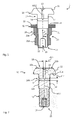
- Fig. 1 shows an example of a mounting bracket 1.
- the mounting bracket 1 has a bolt 10, a pin securing member 20 and a disc 30.
- the bolt 10 is in Fig. 2 shown individually and in particular has a contact portion 11 and a shaft 12.
- the shaft 12 is rod-shaped and extends in a longitudinal direction L.
- the shaft 12 may have a circular cross-section.
- the abutment portion 11 is preferably arranged with respect to the longitudinal direction L at a first end portion 17 of the shaft 12.
- the abutting portion 11 projects generally in a radial direction R from a peripheral surface 12 a of the shaft 12.
- the Fig. 1 and 2 as well as the FIGS. 5 and 6 each show an example of an executed as a head contact portion 11 with a circumferential, continuous contact surface 11a.
- the abutment portion 11 may be formed, for example, by discrete, individual lugs, which project respectively from the peripheral surface 12a of the shaft 12. As in the Fig. 1 and 2 as well as the FIGS. 5 and 6 is shown, the abutment portion 11 preferably forms an end 18 of the bolt 10 with respect to the longitudinal direction L.
- the shaft 12 has an injection longitudinal channel 13 extending along the longitudinal direction L and an injection transverse channel 14 extending between the injection longitudinal channel 13 and the outer circumferential surface 12a of the shaft 12.
- an extension of the longitudinal injection channel 13 in the longitudinal direction L, in particular along a central axis M12 of the shaft 12 is shown by way of example.
- the longitudinal injection channel 13 may also extend laterally offset to the central axis M12 and in particular generally along the longitudinal direction L.
- the injection longitudinal passage 13 preferably extends from the abutment portion 11 in the shaft 12.
- the injection longitudinal channel 13 in particular as a bore of an end face 10s of the bolt 10, which is presently formed by a with respect to the longitudinal direction L opposite to the contact surface 11a located end face 11b of the abutment portion 11, introduced into the shaft 12.
- the longitudinal injection channel 13 may extend into the shaft 12 from an end 15 of the bolt opposite the abutment portion 11 with respect to the longitudinal direction L (not shown).
- the longitudinal injection channel 13 preferably has a diameter d13 in a range between 0.5 mm and 2.5 mm.
- the longitudinal injection channel 13 has a circular cross-section.
- other cross-sectional shapes are conceivable, for example rectangular, triangular or the like.
- the diameter is given in particular as the diameter of a circle whose surface area is identical to the surface area of the cross-sectional area defined by the cross-section of the longitudinal injection channel 13.
- the injection transverse channel 14 extends between the injection longitudinal channel 13 and the outer peripheral surface 12a of the shaft 12. More specifically, the injection transverse channel 14 connects an opening 14A of the outer peripheral surface 12a of the shaft 12 to the injection transverse channel 14.
- FIGS Fig. 1, 2 . 5 and 6 is shown by way of example that the injection transverse channel 14 extends perpendicular to the central axis M12 of the shaft 12.
- the injection transverse channel 14 extends transversely to the longitudinal direction L, but generally the injection transverse channel 14 extends between the two Injection longitudinal channel 13 and the outer peripheral surface 12a of the shaft 12 and can assume any inclinations with respect to the longitudinal direction L.
- the injection cross channel 14 is exemplified as a through bore extending through the shaft 12.
- the injection transverse channel 14 can also be designed as a blind hole ending in the cross section of the shaft 12. It is also conceivable to provide a plurality of injection transverse channels 14.
- the injection transverse channel 14 preferably has a diameter d14 in a range between 0.5 mm and 2.5 mm.
- the injection transverse channel 14 has a circular cross section.
- other cross-sectional shapes are conceivable, for example rectangular, triangular or the like.
- the diameter is given in particular as the diameter of a circle whose surface area is identical to the surface area of the cross-sectional area defined by the cross-section of the injection transverse channel 14.
- an external thread 16 may be formed on the outer peripheral surface 12a of the shaft 12. This can be formed in relation to the longitudinal direction L in particular only in a partial section of the outer peripheral surface 12a.
- FIG. 2 shows that at the opposite to the abutment portion 11 located end 15 of the shaft 12, an engagement portion 19 may be formed.
- the engagement portion 19 in particular as a in the longitudinal direction L in the shaft 12 extending into recess formed with a hexagon socket.
- the engagement portion 19 is provided for engagement with a torque application device.
- Fig. 1 the fastening mounting kit 1 is shown in an assembled state, in which the bolt securing element 20 is fixed to the shaft 12 of the bolt 10 and the disc 30 is arranged with respect to the longitudinal direction L between the bolt securing element 20 and the abutment portion 11 of the bolt 10.
- Fig. 1 shows an example of an advantageous design of the bolt securing element 20 as a sleeve 21.
- the sleeve 21 has an internal thread 22. This can be in With respect to the longitudinal extension of the sleeve 21 may be provided over its entire length or, as in Fig. 1 shown by way of example only in a first longitudinal section 21A of the sleeve 21.
- the sleeve 21 preferably has a notch 23 extending in a circumferential direction of the sleeve 21.
- the notch 23 locally reduces the cross-sectional thickness of the sleeve 21 and is arranged with respect to the longitudinal extent of the sleeve 21, for example in a transition region from the first longitudinal portion 21A to a second longitudinal portion 21B of the sleeve 21.
- a predetermined breaking point of the sleeve 21 is formed by the notch 23, at which the sleeve 21 ruptures or breaks upon application of a predetermined torque.
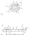
- the disc 30 has in particular a first surface 30a and a second surface 30b oriented opposite thereto, the first and second surfaces 30a, 30b being connected by a circumferential surface 30c.
- the disc has a recess 31, through which the shaft 12 of the bolt 10 can be passed, as for example in Fig. 1 is shown.
- the recess 30 extends in particular between the first and the second surface 30a, 30b of the disc 30.
- the recess 31 is formed as a circular recess 31.
- the recess 31 has an adapted to the cross-sectional shape of the shaft 12 of the bolt 10, so advantageously has the same cross-sectional shape.
- the disc 30 has an outer vent groove 33 and an inner vent groove 34.
- the outer vent groove 33 and the inner vent groove 34 are respectively formed on and through the first surface 30 a of the disk 30.
- the outer vent groove 33 extends from a peripheral edge 32 of the disc 30, in particular from the peripheral surface 30c of the disc 30 in the direction of the recess 31.
- the inner vent groove 34 extends along the recess 31, wherein the outer vent groove 33 opens into the inner vent groove 34 ,
- the outer vent groove 33 thus extends in particular between the peripheral surface 30 c of the disc 30 and the inner vent groove 34.
- the inner vent groove 34 preferably extends as a closed ring, in particular concentrically around the recess 31 around. Generally, the inner vent groove 34 extends along the Recess 31. In particular, the inner vent groove 34 can thus extend only over a portion of the circumference of the recess 31.
- the inner and outer vent grooves 33, 34 advantageously each have a U-shaped cross-section.
- other cross-sectional shapes are conceivable, for example, V-shaped, rectangular or the like.
- the inner and outer vent grooves 33, 34 each have the same groove depth t33, t34.
- the outer vent groove 33 and the inner vent groove 34 each have a groove depth t33, t34 in a range between 0.1 mm and 1 mm.
- the disk 30 is exemplified in each case as a separate component of the bolt securing element 20.
- the disc 30 may also be formed integrally with the pin securing element 20 (not shown).
- the disk 30 preferably has a thickness t30 in a range between 0.8 mm and 2.5 mm.
- An outer diameter d30 of the disc is preferably in a range between 5 mm and 20 mm.
- a diameter d31 of the recess 31 is preferably in a range between 3 mm and 15 mm.
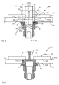
- Fig. 5 shows an example of a component assembly 100 during the implementation of a method for its formation.
- a component fixing assembly 99 for forming the component assembly 100 with first component 101, a second component 102 and the mounting assembly set 1.
- the first component 101 has a first through hole 103.
- the second component 102 has a second through-bore 104.
- the first and second members 102 are disposed relative to each other so that the first through hole 103 and the second through hole 104 are superimposed.
- Fig. 5 shows an example of a component assembly 100 during the implementation of a method for its formation.
- Fig. 5 shows a component fixing assembly 99 for forming the component assembly 100 with first component 101, a second component 102 and the mounting assembly set 1.
- the first component 101 has a first through hole 103.
- the second component 102 has a second through-bor
- the first and the second through-bores 103, 104 have different diameters d103, d104 are executed.
- the first through-hole 103 has a smaller diameter d103 than the second through-hole 104, as shown in FIGS FIGS. 5 and 6 is shown by way of example.
- the second through-hole 104 is located, as in Fig. 5 is shown by way of example.
- the second component 102 abuts with a first surface 101a on a second surface 101b of the first component 101, as in FIG Fig. 5 is shown.
- the first component 101 is made of a metal material and the second component 102 is designed as a fiber composite component.
- the components 101, 102 may be designed as a fiber composite component.
- the shank 12 of the bolt 10 of the mounting bracket 1 extends through the first through hole 103 and the second through hole 104. Furthermore, the abutment portion 11 bears against the first component 101. In particular, the abutment surface 11a of the abutment portion 11 bears against a first surface 101a of the first component 101, the first surface 101a of the first component 101 being oriented opposite to the second surface 101b of the first component 101.
- Fig. 5 shows by way of example an advantageous design in which the shaft 12 rests with its outer peripheral surface 12a on the first through hole 103 defining the soffit surface or inner surface 101i of the first component 101.
- a first tolerance space (not shown) may also extend.
- a second tolerance space (not shown) between the outer peripheral surface 12a of the shaft 12 and the second through-bore 104 defining the soffit surface or inner surface 102i of the second component 102 extends a second tolerance space, as exemplified in Fig. 5 is shown.
- the second tolerance space and the possibly existing first tolerance space together form an inner space 105. This therefore extends generally at least between the shaft 12 and the second component 102 within the second through-bore 104.
- a specific positioning of the injection transverse channel 14 relative to the second surface 101b of the first component 101 is preferably carried out.
- a section 14B of an edge of the injection transverse channel 14 of the bolt facing the contact portion 11 of the bolt 10 is aligned with respect to the longitudinal direction L. 10 with the second surface 101b of the first component 101.
- the edge of the injection transverse channel 14 is defined in particular by the surface area of the surface 12a defining the opening 14A.
- the disk 30 abuts against the second component 102.
- the disk 30 abuts with the first surface 30a on a second surface 102b of the second component 102 oriented opposite to the first surface 102a of the second component 102.
- the inner vent groove 34 faces the second member 102 and is disposed within the second through hole 104 with respect to the radial direction R, as shown by way of example in FIGS FIGS. 5 and 6 is shown.
- the bolt securing element 20 is fixed to the shaft 12 of the bolt 10.
- the pin securing element 20 is formed as the sleeve 21 described above, which is screwed onto the external thread 16 of the shaft 12.
- the pin securing member 20 clamps the first and second members 101, 102 between the abutment portion 11 of the bolt 10 and the disk 30 with respect to the longitudinal direction L.
- Fig. 6 shows the component assembly 100, which is outgoing from the in Fig. 5 shown component fixing assembly 99 has been formed.
- an inner space 105 extending at least between the shaft 12 and the second component 102 within the second through-bore 104 is filled with a hardened filling material 110.
- the component assembly 100 is formed by injecting the curable filler 110 in a liquid state into the injection longitudinal channel 13 of the bolt. Via the injection transverse channel 14, the liquid filling material 110 enters the interior 105 and fills it. Before injecting in the interior 105 located air is discharged through the outer vent groove 33.
- filling material 105 is injected until it exits the outer venting groove 33, as shown by way of example in FIG Fig. 6 is shown. Finally, hardening of the filling material 105 takes place, for example by heating it.
- the filling material 110 may be formed in particular by an epoxy resin.
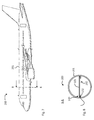
- Fig. 7 shows an example of an aircraft 200 in the form of an aircraft, which has the component assembly 100.
- Fig. 8 shows schematically and in a simplified manner, a sectional view of a fuselage 201 of the aircraft 200.
- the component assembly 100 can be used in particular for connecting a bottom 202 with a fuselage structure.
- the first component 101 of the component assembly 100 may be formed, for example, by a plate forming the bottom.
- the second component 102 of the component arrangement 100 can be formed for example by a bulkhead.
Landscapes
- Engineering & Computer Science (AREA)
- General Engineering & Computer Science (AREA)
- Mechanical Engineering (AREA)
- Connection Of Plates (AREA)
Priority Applications (1)
| Application Number | Priority Date | Filing Date | Title |
|---|---|---|---|
| EP16191520.2A EP3301310B1 (fr) | 2016-09-29 | 2016-09-29 | Visserie de fixation, système de composant et procédé de conformation d'un système de composant |
Applications Claiming Priority (1)
| Application Number | Priority Date | Filing Date | Title |
|---|---|---|---|
| EP16191520.2A EP3301310B1 (fr) | 2016-09-29 | 2016-09-29 | Visserie de fixation, système de composant et procédé de conformation d'un système de composant |
Publications (2)
| Publication Number | Publication Date |
|---|---|
| EP3301310A1 true EP3301310A1 (fr) | 2018-04-04 |
| EP3301310B1 EP3301310B1 (fr) | 2021-10-27 |
Family
ID=57130163
Family Applications (1)
| Application Number | Title | Priority Date | Filing Date |
|---|---|---|---|
| EP16191520.2A Active EP3301310B1 (fr) | 2016-09-29 | 2016-09-29 | Visserie de fixation, système de composant et procédé de conformation d'un système de composant |
Country Status (1)
| Country | Link |
|---|---|
| EP (1) | EP3301310B1 (fr) |
Cited By (2)
| Publication number | Priority date | Publication date | Assignee | Title |
|---|---|---|---|---|
| CN110371697A (zh) * | 2019-08-09 | 2019-10-25 | 河南宾康智能装备有限公司 | 一种码砖机用定位式可快速更换卡头 |
| DE102024108575A1 (de) * | 2024-03-26 | 2025-10-02 | Dr. Ing. H.C. F. Porsche Aktiengesellschaft | Schraubendreheinheit zum Anziehen einer Schraube |
Citations (4)
| Publication number | Priority date | Publication date | Assignee | Title |
|---|---|---|---|---|
| EP1239114A1 (fr) * | 2001-03-09 | 2002-09-11 | HILTI Aktiengesellschaft | Rondelle pour ancrage par ciment injecté |
| DE202010011671U1 (de) * | 2010-08-21 | 2011-09-02 | Karin Henning | Injektage-Unterlegscheibe für Schrauben, Dübel, Anker |
| US20130330145A1 (en) | 2012-06-11 | 2013-12-12 | Board Of Trustees Of Michigan State University | Hybrid fastener |
| US9403558B1 (en) * | 2015-05-15 | 2016-08-02 | GM Global Technology Operations LLC | Engine mount assembly |
-
2016
- 2016-09-29 EP EP16191520.2A patent/EP3301310B1/fr active Active
Patent Citations (4)
| Publication number | Priority date | Publication date | Assignee | Title |
|---|---|---|---|---|
| EP1239114A1 (fr) * | 2001-03-09 | 2002-09-11 | HILTI Aktiengesellschaft | Rondelle pour ancrage par ciment injecté |
| DE202010011671U1 (de) * | 2010-08-21 | 2011-09-02 | Karin Henning | Injektage-Unterlegscheibe für Schrauben, Dübel, Anker |
| US20130330145A1 (en) | 2012-06-11 | 2013-12-12 | Board Of Trustees Of Michigan State University | Hybrid fastener |
| US9403558B1 (en) * | 2015-05-15 | 2016-08-02 | GM Global Technology Operations LLC | Engine mount assembly |
Cited By (3)
| Publication number | Priority date | Publication date | Assignee | Title |
|---|---|---|---|---|
| CN110371697A (zh) * | 2019-08-09 | 2019-10-25 | 河南宾康智能装备有限公司 | 一种码砖机用定位式可快速更换卡头 |
| CN110371697B (zh) * | 2019-08-09 | 2024-03-15 | 河南宾康智能装备有限公司 | 一种码砖机用定位式可快速更换卡头 |
| DE102024108575A1 (de) * | 2024-03-26 | 2025-10-02 | Dr. Ing. H.C. F. Porsche Aktiengesellschaft | Schraubendreheinheit zum Anziehen einer Schraube |
Also Published As
| Publication number | Publication date |
|---|---|
| EP3301310B1 (fr) | 2021-10-27 |
Similar Documents
| Publication | Publication Date | Title |
|---|---|---|
| DE4033763C2 (de) | Vorrichtung zum Sichern einer in einer Öffnung in einer Verkleidung aufgenommenen Mutter | |
| EP2720907B1 (fr) | Dispositif de fixation comprenant un compensateur de tolérance | |
| EP2082143B1 (fr) | Association composée d'une vis, d'une rondelle et d'une douille, et procédé de production d'une telle combinaison | |
| DE102019113663B4 (de) | Abstandhalter für eine befestigungsanordnung, befestigungsanordnung mit einem solchen abstandhalter sowie verfahren zum befestigen eines montageteils an einem trägerteil | |
| EP3079927B1 (fr) | Ensemble composé d'un élément de châssis et d'un élément d'assemblage et procédé pour fixer une élément d'assemblage à un élément de châssis | |
| WO2019091945A1 (fr) | Dispositif anti-détachement pour vis et unité de montage | |
| WO2008125076A1 (fr) | Ressort à lame constitué d'un matériau composite fibres-matière plastique et élément d'application d'une force pour ce ressort | |
| DE69611885T2 (de) | Verbindungselement | |
| EP3301310B1 (fr) | Visserie de fixation, système de composant et procédé de conformation d'un système de composant | |
| EP3382216B1 (fr) | Came de retenue et système de fermeture rapide correspondant | |
| EP3885591B1 (fr) | Dispositif de fixation | |
| DE29809130U1 (de) | Dichtung, insbesondere für Kraftfahrzeuge | |
| EP1724495B1 (fr) | Transmission à courroie crantée et procédé de fabrication d'un poulie pour transmission à courroie crantée | |
| EP3978360B1 (fr) | Cadre de fenêtre pour un véhicule et procédé de fabrication d'un cadre de fenêtre | |
| DE102020132066B4 (de) | Verfahren zum Befestigen eines Beschlags sowie Befestigungselement | |
| DE102012006524A1 (de) | Schraube mit einem Führungselement | |
| WO2012013352A1 (fr) | Pré-ébauche pour une partie d'habillage intérieur d'un véhicule et une partie d'habillage intérieur | |
| DE2619728C3 (de) | Blindbefestiger, insbesondere zur Anwendung bei einer Beplankung eines Flugzeugs o.dgl | |
| WO2005071271A1 (fr) | Assemblage, bloc de montage et element support pour cet assemblage, et procede associe | |
| EP3244074B1 (fr) | Dispositif de fixation sur un composant | |
| DE102022203669B4 (de) | Befestigungsvorrichtung, Schraubverbund, Kraftfahrzeug und Verfahren zum Verbinden von Bauteilen | |
| EP3008350A1 (fr) | Assemblage fileté d'au moins deux éléments adjacents | |
| DE102013011967A1 (de) | Schraubverbindungselement für ein Kraftfahrzeug | |
| DE10327981B4 (de) | Gewindeeinsatz einer Einrichtung zum lösbaren Verbinden zweier Bauteile | |
| EP3530965A1 (fr) | Agencement d'un corps creux et d'un élément de renforcement, procédé de fabrication dudit agencement ainsi qu'élément de renforcement |
Legal Events
| Date | Code | Title | Description |
|---|---|---|---|
| PUAI | Public reference made under article 153(3) epc to a published international application that has entered the european phase |
Free format text: ORIGINAL CODE: 0009012 |
|
| STAA | Information on the status of an ep patent application or granted ep patent |
Free format text: STATUS: THE APPLICATION HAS BEEN PUBLISHED |
|
| AK | Designated contracting states |
Kind code of ref document: A1 Designated state(s): AL AT BE BG CH CY CZ DE DK EE ES FI FR GB GR HR HU IE IS IT LI LT LU LV MC MK MT NL NO PL PT RO RS SE SI SK SM TR |
|
| AX | Request for extension of the european patent |
Extension state: BA ME |
|
| STAA | Information on the status of an ep patent application or granted ep patent |
Free format text: STATUS: REQUEST FOR EXAMINATION WAS MADE |
|
| 17P | Request for examination filed |
Effective date: 20181002 |
|
| RBV | Designated contracting states (corrected) |
Designated state(s): AL AT BE BG CH CY CZ DE DK EE ES FI FR GB GR HR HU IE IS IT LI LT LU LV MC MK MT NL NO PL PT RO RS SE SI SK SM TR |
|
| GRAP | Despatch of communication of intention to grant a patent |
Free format text: ORIGINAL CODE: EPIDOSNIGR1 |
|
| STAA | Information on the status of an ep patent application or granted ep patent |
Free format text: STATUS: GRANT OF PATENT IS INTENDED |
|
| INTG | Intention to grant announced |
Effective date: 20210617 |
|
| GRAS | Grant fee paid |
Free format text: ORIGINAL CODE: EPIDOSNIGR3 |
|
| GRAA | (expected) grant |
Free format text: ORIGINAL CODE: 0009210 |
|
| STAA | Information on the status of an ep patent application or granted ep patent |
Free format text: STATUS: THE PATENT HAS BEEN GRANTED |
|
| AK | Designated contracting states |
Kind code of ref document: B1 Designated state(s): AL AT BE BG CH CY CZ DE DK EE ES FI FR GB GR HR HU IE IS IT LI LT LU LV MC MK MT NL NO PL PT RO RS SE SI SK SM TR |
|
| REG | Reference to a national code |
Ref country code: GB Ref legal event code: FG4D Free format text: NOT ENGLISH |
|
| REG | Reference to a national code |
Ref country code: CH Ref legal event code: EP |
|
| REG | Reference to a national code |
Ref country code: AT Ref legal event code: REF Ref document number: 1442048 Country of ref document: AT Kind code of ref document: T Effective date: 20211115 |
|
| REG | Reference to a national code |
Ref country code: DE Ref legal event code: R096 Ref document number: 502016014042 Country of ref document: DE |
|
| REG | Reference to a national code |
Ref country code: IE Ref legal event code: FG4D Free format text: LANGUAGE OF EP DOCUMENT: GERMAN |
|
| REG | Reference to a national code |
Ref country code: LT Ref legal event code: MG9D |
|
| REG | Reference to a national code |
Ref country code: NL Ref legal event code: MP Effective date: 20211027 |
|
| PG25 | Lapsed in a contracting state [announced via postgrant information from national office to epo] |
Ref country code: RS Free format text: LAPSE BECAUSE OF FAILURE TO SUBMIT A TRANSLATION OF THE DESCRIPTION OR TO PAY THE FEE WITHIN THE PRESCRIBED TIME-LIMIT Effective date: 20211027 Ref country code: LT Free format text: LAPSE BECAUSE OF FAILURE TO SUBMIT A TRANSLATION OF THE DESCRIPTION OR TO PAY THE FEE WITHIN THE PRESCRIBED TIME-LIMIT Effective date: 20211027 Ref country code: FI Free format text: LAPSE BECAUSE OF FAILURE TO SUBMIT A TRANSLATION OF THE DESCRIPTION OR TO PAY THE FEE WITHIN THE PRESCRIBED TIME-LIMIT Effective date: 20211027 Ref country code: BG Free format text: LAPSE BECAUSE OF FAILURE TO SUBMIT A TRANSLATION OF THE DESCRIPTION OR TO PAY THE FEE WITHIN THE PRESCRIBED TIME-LIMIT Effective date: 20220127 |
|
| PG25 | Lapsed in a contracting state [announced via postgrant information from national office to epo] |
Ref country code: IS Free format text: LAPSE BECAUSE OF FAILURE TO SUBMIT A TRANSLATION OF THE DESCRIPTION OR TO PAY THE FEE WITHIN THE PRESCRIBED TIME-LIMIT Effective date: 20220227 Ref country code: SE Free format text: LAPSE BECAUSE OF FAILURE TO SUBMIT A TRANSLATION OF THE DESCRIPTION OR TO PAY THE FEE WITHIN THE PRESCRIBED TIME-LIMIT Effective date: 20211027 Ref country code: PT Free format text: LAPSE BECAUSE OF FAILURE TO SUBMIT A TRANSLATION OF THE DESCRIPTION OR TO PAY THE FEE WITHIN THE PRESCRIBED TIME-LIMIT Effective date: 20220228 Ref country code: PL Free format text: LAPSE BECAUSE OF FAILURE TO SUBMIT A TRANSLATION OF THE DESCRIPTION OR TO PAY THE FEE WITHIN THE PRESCRIBED TIME-LIMIT Effective date: 20211027 Ref country code: NO Free format text: LAPSE BECAUSE OF FAILURE TO SUBMIT A TRANSLATION OF THE DESCRIPTION OR TO PAY THE FEE WITHIN THE PRESCRIBED TIME-LIMIT Effective date: 20220127 Ref country code: NL Free format text: LAPSE BECAUSE OF FAILURE TO SUBMIT A TRANSLATION OF THE DESCRIPTION OR TO PAY THE FEE WITHIN THE PRESCRIBED TIME-LIMIT Effective date: 20211027 Ref country code: LV Free format text: LAPSE BECAUSE OF FAILURE TO SUBMIT A TRANSLATION OF THE DESCRIPTION OR TO PAY THE FEE WITHIN THE PRESCRIBED TIME-LIMIT Effective date: 20211027 Ref country code: HR Free format text: LAPSE BECAUSE OF FAILURE TO SUBMIT A TRANSLATION OF THE DESCRIPTION OR TO PAY THE FEE WITHIN THE PRESCRIBED TIME-LIMIT Effective date: 20211027 Ref country code: GR Free format text: LAPSE BECAUSE OF FAILURE TO SUBMIT A TRANSLATION OF THE DESCRIPTION OR TO PAY THE FEE WITHIN THE PRESCRIBED TIME-LIMIT Effective date: 20220128 Ref country code: ES Free format text: LAPSE BECAUSE OF FAILURE TO SUBMIT A TRANSLATION OF THE DESCRIPTION OR TO PAY THE FEE WITHIN THE PRESCRIBED TIME-LIMIT Effective date: 20211027 |
|
| REG | Reference to a national code |
Ref country code: DE Ref legal event code: R097 Ref document number: 502016014042 Country of ref document: DE |
|
| PG25 | Lapsed in a contracting state [announced via postgrant information from national office to epo] |
Ref country code: SM Free format text: LAPSE BECAUSE OF FAILURE TO SUBMIT A TRANSLATION OF THE DESCRIPTION OR TO PAY THE FEE WITHIN THE PRESCRIBED TIME-LIMIT Effective date: 20211027 Ref country code: SK Free format text: LAPSE BECAUSE OF FAILURE TO SUBMIT A TRANSLATION OF THE DESCRIPTION OR TO PAY THE FEE WITHIN THE PRESCRIBED TIME-LIMIT Effective date: 20211027 Ref country code: RO Free format text: LAPSE BECAUSE OF FAILURE TO SUBMIT A TRANSLATION OF THE DESCRIPTION OR TO PAY THE FEE WITHIN THE PRESCRIBED TIME-LIMIT Effective date: 20211027 Ref country code: EE Free format text: LAPSE BECAUSE OF FAILURE TO SUBMIT A TRANSLATION OF THE DESCRIPTION OR TO PAY THE FEE WITHIN THE PRESCRIBED TIME-LIMIT Effective date: 20211027 Ref country code: DK Free format text: LAPSE BECAUSE OF FAILURE TO SUBMIT A TRANSLATION OF THE DESCRIPTION OR TO PAY THE FEE WITHIN THE PRESCRIBED TIME-LIMIT Effective date: 20211027 Ref country code: CZ Free format text: LAPSE BECAUSE OF FAILURE TO SUBMIT A TRANSLATION OF THE DESCRIPTION OR TO PAY THE FEE WITHIN THE PRESCRIBED TIME-LIMIT Effective date: 20211027 |
|
| PLBE | No opposition filed within time limit |
Free format text: ORIGINAL CODE: 0009261 |
|
| STAA | Information on the status of an ep patent application or granted ep patent |
Free format text: STATUS: NO OPPOSITION FILED WITHIN TIME LIMIT |
|
| 26N | No opposition filed |
Effective date: 20220728 |
|
| PG25 | Lapsed in a contracting state [announced via postgrant information from national office to epo] |
Ref country code: AL Free format text: LAPSE BECAUSE OF FAILURE TO SUBMIT A TRANSLATION OF THE DESCRIPTION OR TO PAY THE FEE WITHIN THE PRESCRIBED TIME-LIMIT Effective date: 20211027 |
|
| PG25 | Lapsed in a contracting state [announced via postgrant information from national office to epo] |
Ref country code: SI Free format text: LAPSE BECAUSE OF FAILURE TO SUBMIT A TRANSLATION OF THE DESCRIPTION OR TO PAY THE FEE WITHIN THE PRESCRIBED TIME-LIMIT Effective date: 20211027 |
|
| PG25 | Lapsed in a contracting state [announced via postgrant information from national office to epo] |
Ref country code: MC Free format text: LAPSE BECAUSE OF FAILURE TO SUBMIT A TRANSLATION OF THE DESCRIPTION OR TO PAY THE FEE WITHIN THE PRESCRIBED TIME-LIMIT Effective date: 20211027 |
|
| REG | Reference to a national code |
Ref country code: CH Ref legal event code: PL |
|
| REG | Reference to a national code |
Ref country code: BE Ref legal event code: MM Effective date: 20220930 |
|
| PG25 | Lapsed in a contracting state [announced via postgrant information from national office to epo] |
Ref country code: IT Free format text: LAPSE BECAUSE OF FAILURE TO SUBMIT A TRANSLATION OF THE DESCRIPTION OR TO PAY THE FEE WITHIN THE PRESCRIBED TIME-LIMIT Effective date: 20211027 |
|
| PG25 | Lapsed in a contracting state [announced via postgrant information from national office to epo] |
Ref country code: LU Free format text: LAPSE BECAUSE OF NON-PAYMENT OF DUE FEES Effective date: 20220929 |
|
| PG25 | Lapsed in a contracting state [announced via postgrant information from national office to epo] |
Ref country code: LI Free format text: LAPSE BECAUSE OF NON-PAYMENT OF DUE FEES Effective date: 20220930 Ref country code: IE Free format text: LAPSE BECAUSE OF NON-PAYMENT OF DUE FEES Effective date: 20220929 Ref country code: CH Free format text: LAPSE BECAUSE OF NON-PAYMENT OF DUE FEES Effective date: 20220930 |
|
| PG25 | Lapsed in a contracting state [announced via postgrant information from national office to epo] |
Ref country code: BE Free format text: LAPSE BECAUSE OF NON-PAYMENT OF DUE FEES Effective date: 20220930 |
|
| REG | Reference to a national code |
Ref country code: AT Ref legal event code: MM01 Ref document number: 1442048 Country of ref document: AT Kind code of ref document: T Effective date: 20220929 |
|
| PG25 | Lapsed in a contracting state [announced via postgrant information from national office to epo] |
Ref country code: AT Free format text: LAPSE BECAUSE OF NON-PAYMENT OF DUE FEES Effective date: 20220929 |
|
| PG25 | Lapsed in a contracting state [announced via postgrant information from national office to epo] |
Ref country code: HU Free format text: LAPSE BECAUSE OF FAILURE TO SUBMIT A TRANSLATION OF THE DESCRIPTION OR TO PAY THE FEE WITHIN THE PRESCRIBED TIME-LIMIT; INVALID AB INITIO Effective date: 20160929 |
|
| PG25 | Lapsed in a contracting state [announced via postgrant information from national office to epo] |
Ref country code: CY Free format text: LAPSE BECAUSE OF FAILURE TO SUBMIT A TRANSLATION OF THE DESCRIPTION OR TO PAY THE FEE WITHIN THE PRESCRIBED TIME-LIMIT Effective date: 20211027 |
|
| PG25 | Lapsed in a contracting state [announced via postgrant information from national office to epo] |
Ref country code: MK Free format text: LAPSE BECAUSE OF FAILURE TO SUBMIT A TRANSLATION OF THE DESCRIPTION OR TO PAY THE FEE WITHIN THE PRESCRIBED TIME-LIMIT Effective date: 20211027 |
|
| PG25 | Lapsed in a contracting state [announced via postgrant information from national office to epo] |
Ref country code: MT Free format text: LAPSE BECAUSE OF FAILURE TO SUBMIT A TRANSLATION OF THE DESCRIPTION OR TO PAY THE FEE WITHIN THE PRESCRIBED TIME-LIMIT Effective date: 20211027 |
|
| PGFP | Annual fee paid to national office [announced via postgrant information from national office to epo] |
Ref country code: DE Payment date: 20250919 Year of fee payment: 10 |
|
| PGFP | Annual fee paid to national office [announced via postgrant information from national office to epo] |
Ref country code: GB Payment date: 20250919 Year of fee payment: 10 |
|
| PGFP | Annual fee paid to national office [announced via postgrant information from national office to epo] |
Ref country code: FR Payment date: 20250922 Year of fee payment: 10 |
|
| PG25 | Lapsed in a contracting state [announced via postgrant information from national office to epo] |
Ref country code: TR Free format text: LAPSE BECAUSE OF FAILURE TO SUBMIT A TRANSLATION OF THE DESCRIPTION OR TO PAY THE FEE WITHIN THE PRESCRIBED TIME-LIMIT Effective date: 20211027 |