EP3301320B1 - Drehdämpfer - Google Patents
Drehdämpfer Download PDFInfo
- Publication number
- EP3301320B1 EP3301320B1 EP17194080.2A EP17194080A EP3301320B1 EP 3301320 B1 EP3301320 B1 EP 3301320B1 EP 17194080 A EP17194080 A EP 17194080A EP 3301320 B1 EP3301320 B1 EP 3301320B1
- Authority
- EP
- European Patent Office
- Prior art keywords
- rotor
- housing
- rotary damper
- opening
- damper
- Prior art date
- Legal status (The legal status is an assumption and is not a legal conclusion. Google has not performed a legal analysis and makes no representation as to the accuracy of the status listed.)
- Active
Links
Images





Classifications
-
- F—MECHANICAL ENGINEERING; LIGHTING; HEATING; WEAPONS; BLASTING
- F16—ENGINEERING ELEMENTS AND UNITS; GENERAL MEASURES FOR PRODUCING AND MAINTAINING EFFECTIVE FUNCTIONING OF MACHINES OR INSTALLATIONS; THERMAL INSULATION IN GENERAL
- F16F—SPRINGS; SHOCK-ABSORBERS; MEANS FOR DAMPING VIBRATION
- F16F9/00—Springs, vibration-dampers, shock-absorbers, or similarly-constructed movement-dampers using a fluid or the equivalent as damping medium
- F16F9/10—Springs, vibration-dampers, shock-absorbers, or similarly-constructed movement-dampers using a fluid or the equivalent as damping medium using liquid only; using a fluid of which the nature is immaterial
- F16F9/14—Devices with one or more members, e.g. pistons, vanes, moving to and fro in chambers and using throttling effect
- F16F9/145—Devices with one or more members, e.g. pistons, vanes, moving to and fro in chambers and using throttling effect involving only rotary movement of the effective parts
-
- F—MECHANICAL ENGINEERING; LIGHTING; HEATING; WEAPONS; BLASTING
- F16—ENGINEERING ELEMENTS AND UNITS; GENERAL MEASURES FOR PRODUCING AND MAINTAINING EFFECTIVE FUNCTIONING OF MACHINES OR INSTALLATIONS; THERMAL INSULATION IN GENERAL
- F16F—SPRINGS; SHOCK-ABSORBERS; MEANS FOR DAMPING VIBRATION
- F16F2228/00—Functional characteristics, e.g. variability, frequency-dependence
- F16F2228/14—Functional characteristics, e.g. variability, frequency-dependence progressive
-
- F—MECHANICAL ENGINEERING; LIGHTING; HEATING; WEAPONS; BLASTING
- F16—ENGINEERING ELEMENTS AND UNITS; GENERAL MEASURES FOR PRODUCING AND MAINTAINING EFFECTIVE FUNCTIONING OF MACHINES OR INSTALLATIONS; THERMAL INSULATION IN GENERAL
- F16F—SPRINGS; SHOCK-ABSORBERS; MEANS FOR DAMPING VIBRATION
- F16F2230/00—Purpose; Design features
- F16F2230/0052—Physically guiding or influencing
- F16F2230/0064—Physically guiding or influencing using a cam
-
- F—MECHANICAL ENGINEERING; LIGHTING; HEATING; WEAPONS; BLASTING
- F16—ENGINEERING ELEMENTS AND UNITS; GENERAL MEASURES FOR PRODUCING AND MAINTAINING EFFECTIVE FUNCTIONING OF MACHINES OR INSTALLATIONS; THERMAL INSULATION IN GENERAL
- F16F—SPRINGS; SHOCK-ABSORBERS; MEANS FOR DAMPING VIBRATION
- F16F2230/00—Purpose; Design features
- F16F2230/06—Fluid filling or discharging
Definitions
- the present invention relates to a structurally reinforced rotary damper which enables to acquire proper damper function under different loads by keeping the damper fluid viscosity fixed, and enables the damper fluid to be injected into the damper under vacuum.
- the rotary dampers are generally used for providing slow closing function for the door of the product in which they are included as a component.
- the damper is comprised of a housing and rotor group parts that are rotatable relative to each other.
- the rotary damper while being assembled as a component within a system, is operated by fixing the housing part to the system and the rotor being rotary under load, or fixing the rotor to the system and the system being rotary.
- the rotary dampers make angularly limited rotations in both directions on the rotary axis.
- valve piece When rotary dampers are examined in terms of their inner structures and operation principles, there is at least one flap and a valve piece which is movable between the said flap and the rotary damper housing.
- the valve piece provides flow control by performing opening/closing, and such systems are currently being used in the technique.
- United States Patent document no US6393624 an application known in the state of the art, discloses the change of flow sections according to the rotary moment growing in closing direction in different angular positions in the work time of rotary damper, and the structures providing the said change.
- World Intellectual Property Organization document no WO2015190382 an application known in the state of the art, discloses a fluid damper device with which it is possible to suppress lifting of a valve body from a rotary shaft when a rotor is rotated in the direction of opening.
- European Patent document no EP1650468 an application known in the state of the art, discloses a damper includes a housing having an opening, a cover over said opening, a rotor rotatably disposed in said housing, said rotor extending outwardly of said housing through said cover, a seal between said cover and said rotor.
- EP0261051 an application known in the state of the art, discloses a single or oppposite direction damper hinge has a casing rotatably enclosing a rotor.
- Rotary dampers known in the state of the art are formed with the method of filling a specified amount of damper liquid inside the housing piece at a certain stage of the production of and assembling the damper parts later.
- the viscosity of the damper liquid is changed.
- the rotary dampers known in the state of the art are manufactured in certain resistances in order to damp load under different rotary momentums that can be applied. Generally the viscosity of damper liquid is changed in order to obtain dampers with different resistances. For rotary dampers wanted to be acquired in different capacities, using a damper liquid with different viscosity both requires to keep the inconsistencies originating from supply in control, and causes difficulties in production stages of rotary damper relating to the fluid.
- the objective of the present invention is to prevent the presence of air in the fluid volume by means of damper liquid injection by taking damper fluid volume under vacuum, and thus provide a rotary damper which enables the stability of product functions and increases production efficiency.
- Another objective of the present invention is to provide a rotary damper which enables to perform load damping under rotary moments with different amplitudes without changing the fluid viscosity.
- a further objective of the present invention is to provide a rotary damper the resistance of which is increased without expansion in sizes of the system in order to reach large rotary moments.
- a rotary damper (1) which performs load damping function while rotating in one direction in the work time, rotates in other direction without creating resistance and enables to obtain proper function under different loads by keeping the viscosity liquid stable, and to inject the liquid under vacuum; essentially comprises
- the inventive rotary damper (1) performs load damping function while rotating in one direction in the work time, and it rotates in other direction without creating resistance.
- the inventive rotary damper (1) performs load damping function while rotating clockwise (CW), and no-load operation function while rotating counter clockwise (CCW).
- CW clockwise
- CCW counter clockwise
- the rotary damper (1) structure is symmetrical for exact opposite functions. Measurable functions of symmetrical structures are equal.
- the damper housing (2) In order to operate the rotary damper (1) as a component of a system, the damper housing (2) is connected to the fixed part of the system, and the rotor (4) is connected to the part of the system wanted to be covered with effect of the damper.
- the connection of the rotary damper (1) can be carried out in the exact opposite way of the said connection according to the features of the system depending on the requirement of the user. In the detailed descriptions, it is assumed that the rotary damper (1) housing (2) is kept fixed, and the rotor (4) is actuated.
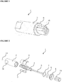
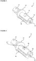
- the rotary damper (1) has a housing (2) comprising a cylindrical shaped space and forming the outer structure.
- the main purpose of the rotary damper (1) parts is to divide the fluid volume into two compartments.
- the damping function of the rotary damper (1) is enabled by controlling the passage of damper liquid between these two compartments in the work time.
- a rotary damper (1) of the present invention has a housing (2) in which an opening comprised of cylindrical or partially cylindrical and curvilinear section or only of curvilinear sections is made.
- a connection surface (21) is provided on the cylindrical surface of the housing (2), and the connection surface (21) has a hollow shape.
- An inner surface (22) forms the inner part of the cylindrical shaped housing (2).
- inner ribs (23) in form of a protrusion extending above the inner surface (22) towards the center. Furthermore, a filling hole (24) is made on the central axis of the housing (2).
- a channel connection opening (25) which has a channel shape starting from the filling hole (24) and extending till the inner rib (23) is made on the flat surface of the housing (2) on which the filling hole (24) is positioned.
- a bearing (3) is placed into the housing (2).
- a bedding surface (31) which is formed by opening the short edge of the bearing (3) in form of a semi-arc, and a hollow shaped cam opening (32) is made on the bedding surface (31).
- a V shaped bearing channel (33) is made on the long edge of the bearing (3).
- a rotor (4) is placed inside the housing (2), and has a cylindrical or curvilinear body section that can rotate such that its central axis will be same as the housing (2).
- the bearing (3) when coupled with the housing (2), comprises the slot which completes the injection line enabling the damper liquid filling process to be performed under rotary damper (1) fluid vacuum and also which is the counterpart of the cam-like structure enabling varying flow section management during rotations of the rotor (4).
- a tail (44) which is located at the end of the cylindrical shaped rotor (4), and the diameter of which is smaller than the diameter of the rotor (4).
- a flange (45) on the rotor (4) and the flange (45) has a cylindrical shape concentrical with the rotor (4).
- a plurality of supporting ribs (46) is used on the rotor (4).
- the supporting ribs (46) that are used are positioned such that they will contact the inner surface of the valve (6).
- a plurality of ribs provided on the rotor (4) is positioned with intervals in between them.
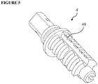
- the flexible surface (64) of the valve (6) flexes with the contact pressure with the sealing rib (49) provided on the supporting ribs (46), and provides sealing.
- a placement opening (47) is made along the central axis of the rotor (4).
- a tail opening (48) is made on the tail (44).
- a support pin (5) is placed into the rotor (4).
- the rotor (4) is manufactured from a thermo-plastic (PA, PBT, POM) material.
- PA thermo-plastic
- PBT thermo-plastic
- POM thermo-plastic
- a valve (6) is placed between the rotor (4) and the housing (2), and the valve (6) is dragged with the movements of the rotor (4) and controls the displacement movements.
- dampers compatible with loads under different rotary moments with fixed viscosity fluid is obtained.
- There is a flexible surface (64) which has an elastic structure extending from the end point of the protrusion (63).
- a metal washer (7) is placed on the rotor (4).
- a cover (8) which is used for covering the open surface of the housing (2).
- the rotor (4) is manufactured from a glass-fiber reinforced thermo-plastic (PA, PBT, POM) material. Additionally, there is a metal washer (7) enabling that ultrasonic plastic welding is performed between the housing (2) and the cover (8) parts without any problems.
- a sealing member (9) is placed between the housing (2) and the cover (8).
- There is an insert piece (11) which is placed into the filling hole (24) located on the housing (2), and which enables the filling hole (24) to be closed tightly after the injection of damper liquid under vacuum.
- the insert piece (11) is manufactured from thermo-plastic or metal materials which may be inform of a sphere or cylinder and which enables to tightly close the filling hole of the housing (2) after the injection of damper liquid under vacuum.
- the housing (2) has a cylindrical structure, or structural details that can position itself around the central axis of a cylindrical space and rotate.
- the housing (2) is connected to the area where desired.
- the inner part of the housing (2) has a structure providing the relations of changing the flow openings required in the work time and sealing relations at the same time.
- the housing (2) comprises the main structure of the injection line enabling the damper liquid to be filled under vacuum.
- the housing (2) is manufactured from a glass-fiber reinforced thermo-plastic (PA, PBT, POM) material.
- the housing (2) can also be comprised of aluminum or zinc alloys.
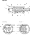
- the structural details of the bearing (3) forms the injection line which is provided both for controlling the flow openings with the rotor (4) in the work time and filling the damper liquid (shown with dashed lines in Figure 11 ).
- the bearing (3) is tightly fitted into the slot formed between the inner ribs (23) located in the housing (2).
- both bedding surface (31) of the bearing (3) is connected with the inner surface (22) inside its slot within the housing (2), and the lateral surfaces of the bearing (3) are connected with the inner surfaces of the structural details which form the slot inside the housing (2) and the length of which (3) is equal to the length of the bearing (3) with the increased surface contact pressures, and this provides required sealing in the work time.
- the bearing (3) part is manufactured from a thermo-plastic material.
- the bearing (3) has a frictional relationship with the rotor (4) having a rotary movement in the work time, and has a surface contact with the rotor (4) part thus providing sealing. Under these conditions, it is possible to prefer POM or PTFE material for bearing (3). This part can be used as it is in symmetrical structures, its symmetry is not required.
- the rotor (4) is positioned in the cylindrical slot within the housing (2) of the cylindrical structure forming the tail (44) part on one side, and it is positioned by bedding the rotor (4) flange in the cylindrical slot located on the inlet part of the housing (2) on the other side.
- the main cylindrical housing (2) structure of the rotor (4) and the cam structure providing the change of the flow opening depending on position are in relation with the tightness providing sealing under certain contact pressures with the bearing (3) part.
- the cylindrical housing (2) structure of the rotor (4) is in continuous contact with the bedding surfaces (31) of the bearing (3) part with a certain amount of tightness. A constant sealing is provided between the surfaces where the housing (2), the bearing and the rotor (4) contacts each other.
- the cam opening (32) of the bearing (3) part changes the flow opening of the first cam face (41) and the second cam face (42) structures located on the rotor (4) depending on the rotor (4) position in the work time.
- the cam opening (32) of the bearing (3) part changes the flow opening of the first cam face (41) and the second cam face (42) structures located on the rotor (4) depending on the rotor (4) position in the work time.
- a certain amount of tightness is acquired, and a controlled sealing is provided in this area.
- first cam face (41) and the second cam face (42) structures located on the rotor (4) for flow opening control applications the start and end values of which are same, but which can be expressed with different curves (shown in Figure 25 ).
- the inner surface of the rotor (4) flange (45) has a contact relation with the outer surfaces of the inner ribs (23) within the housing (2) and its lower surface comprising the tail (44) part of the rotor (4) has a contact relation with the bottom surface of the housing (2) in a certain amount of tightness; and thus the sealing required in the work time is provided.
- the valve (6) is provided between the rotor (4) and the housing (2). It moves together with the rotor (4) on the central axis of the rotary damper (1) system. It has a contact relation both with the rotor (4) and the housing (2) having a certain rate of tightness. Therefore, the sealing required in the work time is provided. Depending on the rotary movements of the rotor (4) in both directions, it opens or closes the flow openings originating from the relations both with the rotor (4) and the housing (2).
- the valve (6) is located on the supporting ribs (46) provided on the rotor (4).
- valve (6) When the inner surfaces of the valve (6) are in contact with the supporting ribs (46) of the rotor, the flow takes place in the openings between the supporting ribs (46) and the valve (6) depending on the rotating direction of the rotor (4).
- the protrusion (63) located on the inner part of the valve (6) piece enables the valve (6) to be rotated by the rotor (4), and it also opens or closes the fluid passage through the channels formed between the valve (6) and the rotor (4).
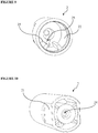
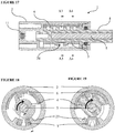
- Figure 23 shows the relation between the valve (6) and the rotor (4) and the damper liquid changing its place in case the rotary damper (1) creating resistance in clockwise (CW) direction rotates in counter clockwise direction (CCW) of its rotor (4).
- the protrusion (63) enabling the valve (6) to be rotated is located in the space between the supporting ribs (46) of the rotor (4).
- One surface of the protrusion (63) enabling the valve (6) to be rotated is in contact with the supporting ribs (46) of the rotor (4).
- Figure 24 shows the function of the valve (6) in case the rotor (4) of the rotary damper (1) rotates in clockwise direction.
- the protrusion (63) on the valve (6) structure is dragged by being contacted by the sealing rib (49) creating a planar area connects the supporting ribs (46) of the rotor (4).
- the flexible surface (64) of the valve (6) changes its form under a contact pressure increased by the sealing rib (49) surface of the rotor (4), thereby providing a sealing. In that case, flow is stopped through the channels formed between the supporting ribs (46) of the rotor (4).
- the valve (6) is also in relation with the inner surface areas (22) which are provided in the inner part of the housing (2) and enable an additional flow opening to be closed or opened depending on the position.
- the said flow opening allows flow in a certain angular area; when the said angular area is passed while the movement is continuing in the same direction and sectional change takes place in the inner surface (22) area of the housing (2), the flow opening is closed by the valve (6).
- the said flow opening control provides a wide flow section for example under the increasing rotary moment applied by the cover parts (furniture, toilet cover, etc.) connected to the damper and moving under the effect of gravitational force onto the rotary damper (1) and until a certain rotary moment is reached.
- valve (6) The flow realized until said flow opening is closed by the valve (6) passes through the cannel (61) area located on the upper part of the valve (6) piece, and it is directed to the other side of the damper inner volume.
- the valve (6) reaching the section change in the inner surface (22) of the housing (2) sweeps the surface with the edge line where its surfaces are connected, and provides sealing in this area.
- the valve (6) piece is the part of the system which is subjected to friction most between the housing (2) and the rotor (4). For this reason, it is favorable to manufacture the valve (6) from a thermo-plastic (for example POM) material.
- a thermo-plastic for example POM
- one of the lateral surfaces of the valve (6) has a contact relation with the bottom surface of the housing (2) in a certain level of tightness, and the other surface of the valve (6) has a contact relation with the surface of the rotor (4) flange (45) remaining on the inner part in a certain level of tightness, thereby providing the sealing required in the work time.
- the sealing member (9) placed into the opening on the rotor (4) is in contact with the inner space of the cover (8) piece. It provides the sealing of the system which operates by rotation.
- the cover (8) and the housing (2) are connected together by means of ultrasonic welding method, and contact pressure is created with the lower surface of the cover (8) in order to obtain the desired tightness in the inner structure.
- the cross sectional area of the orifice (62) should be narrowed for large loads, and widened for small loads.
- the orifice (62) on the valve (6) can be prepared with thermo-plastic injection molding method or an additional puncturing process depending on the production requirements.
- the structural solution provided for injection of rotary damper (1) liquid under vacuum is the structural solution which it provides for filling the rotary damper (1) liquid under vacuum.
- a line is provided which starts from the filling hole (24) of the rotary damper (1) provided on the housing (2) with the connection of the housing (2) and the bearing (3) parts, and which is formed by respectively limiting the space wherein the rotor (4) tail (44) part is bedded inside the housing (2), the channel (61) connection opening located inside the housing (2), and the bearing channel (33) under the bearing (3) with the housing (2), and which ends by the injection hole channel (34) provided on the bearing (3) part opening to the liquid volume of the rotary damper (1).
- the said line being open or closed for filling is related to the positions of the rotor (4) in rotation movement.
- the first position " (a1) is also the position in which the line formed for filling the rotary damper (1) liquid is completely open. Because, the connection hole located on the tail (44) part of the rotor (4) keeps the injection line of the rotor (4) open only in "first position" (a1).
- the "first position " (a1) of the rotor (4) is also suitable in terms of connection of the fluid volume with the injection line, because the first cam face (41) and the second cam face (42) structures located on the rotor (4) and controlling the flow section allow the cam opening (32) formed between the bearing (3) and the rotor (4) to connect with the fluid volume in the widest dimension in first position.
- the fluid first passes through the injection line, and then spreads to the cam opening (32) through the injection hole channel (34) on the bearing (3), and to all of the inner openings from there by means of using a special injection system which connects to the filling hole in the rear part of the housing (2) by providing sealing and after taking the inner openings of the rotary damper (1) under vacuum first, by starting the injection of the damper liquid without changing the sealing or vacuum conditions. Airtight filling is realized by means of the said channel structure.
- An insert piece (11) placed into the filling hole (24) located on the housing (2) is positioned by nailing by means of using a special equipment in order to cut the connection of the rotary damper (1) with the outer environment after filling and to tightly close it. Since the filling hole (24) is a cylindrical opening, the insert piece (11) which is manufactured from thermo-plastic or metal material can be in spherical or cylindrical structure.
- the solution provided for increasing the rigidity and resistance of the rotary damper (1) When the rotor (4) is manufactured from one of the thermo-plastic materials (PA, PBT, POM), it is supported with a metal piece having high strength values so that it can have a long fatigue life under relatively large loads and it has rigidity.
- a support pin (5) in a sufficient length can be placed inside the rotor (4) during production preferably with thermo-plastic injection molding in order to increase twisting resistance.
- the support pin (5) can have a rectangle, eclipse, cylindrical, sections with a plurality of straight edges or triangle sectional area geometry that can be formed with minimum number of edges.
- a support pin (5) having a hexagonal section is preferred in terms of suitability to its function, production and application easiness.
- the support pin (5) having a certain surface roughness or presence of various figures on the surface enables the polymer material to hold on to the support pin (5) better.
Landscapes
- Engineering & Computer Science (AREA)
- General Engineering & Computer Science (AREA)
- Mechanical Engineering (AREA)
- Fluid-Damping Devices (AREA)
Claims (15)
- Rotationsdämpfer (1), der während der Arbeitszeit in eine Richtung rotiert, eine Lastdämpfungsfunktion ausführt, in die andere Richtung rotiert, ohne Widerstand zu schaffen, und ermöglicht es, unter verschiedenen Lasten eine ordnungsgemäße Funktion zu erhalten, indem die Flüssigkeitsviskosität stabil gehalten wird, und die Flüssigkeit unter Vakuum zu injizieren;im Wesentlichen umfassend- mindestens ein Gehäuse (2), in dem ein aus zylindrischen oder teilzylindrischen und gekrümmten Abschnitten oder nur aus gekrümmten Abschnitten bestehender Raum hergestellt ist,- mindestens eine Verbindungsfläche (21), die in Form einer Öffnung auf der äußeren zylindrischen Oberfläche des Gehäuses (2) hergestellt ist,- mindestens eine Innenfläche (22), die den inneren Teil des zylinderförmigen Gehäuses (2) bildet,- mindestens eine innere Rippe (23), die sich in Form eines Vorsprungs über die Innenfläche (22) zur Mitte hin erstreckt,- mindestens eine Füllloch (24), die auf der Mittelachse des Gehäuses (2) hergestellt ist,- mindestens eine Kanalverbindungsöffnung (25), die auf der ebenen Oberfläche des Gehäuses (2), auf der das Füllloch (24) positioniert ist, hergestellt wird, die eine Kanalform aufweist, die von der Füllloch (24) ausgeht und sich bis zur Öffnung zwischen den Innenrippen (23) erstreckt,- mindestens ein Lager (3), das innerhalb des Gehäuses (2) platziert ist und die Steuerung des Durchflusses ermöglicht und eine Trapezform hat,- mindestens eine Bettungsfläche (31), die durch Öffnen der kurzen Kante des Lagers (3) in Form eines Halbbogens bildet,- mindestens eine Nockenöffnung (32), die in Form einer Öffnung auf der Bettungsfläche (31) hergestellt ist,- mindestens einen V-förmigen Lagerkanal (33), der an der Längskante des Lagers (3) hergestellt ist,- mindestens einen Injektionslochkanal (34), der an der Nockenöffnung (32) hergestellt ist und sich bis zum inneren Teil des Lagerkanals (33) erstreckt,- mindestens einen Rotor (4), der im Inneren des Gehäuses (2) platziert ist und der einen zylindrischen oder gekrümmten Körperabschnitt aufweist, der sich so rotieren kann, dass seine Mittelachse mit dem Gehäuse (2) identisch ist,- mindestens eine erste Nockenseite (41), die sich auf der zylindrischen Oberfläche des Rotors (4) befindet und die eine bombenförmige Struktur aufweist,- mindestens ein Heck (44), das sich am Ende des zylinderförmigen Rotors (4) befindet und dessen Durchmesser kleiner als der Durchmesser des Rotors (4) ist,- mindestens einen Flansch (45), der sich auf dem Rotor (4) befindet und der eine zylindrische Form konzentrisch zum Rotor (4) aufweist,- mindestens eine Stützrippe (46), die sich auf der zylindrischen Oberfläche des Rotors (4) befindet und die eine Vorsprungsform aufweist,- mindestens eine Platzierungsöffnung (47), die entlang der Mittelachse des Rotors (4) hergestellt ist,- mindestens eine Hecköffnung (48), die am Heck (44) hergestellt ist,- mindestens einen Stützstift (5), der in die am Rotor (4) hergestellte Platzierungsöffnung platziert wird,- mindestens ein Ventil (6), das zwischen dem Rotor (4) und dem Gehäuse (2) platziert ist, das eine Bogenform hat und das die Flüssigkeitsbewegung steuert, indem es mit den Bewegungen des Rotors (4) gezogen wird,- mindestens einen Kanal (61), der auf der Außenfläche des bogenförmigen Ventils (6) hergestellt ist,- mindestens eine Düse (62), die in den Kanal (61) hergestellt ist,
mindestens einen Vorsprung (63), der sich auf der Innenfläche des bogenförmigen Ventils (6) befindet und der sich linear erstreckt,- mindestens eine flexible Oberfläche (64), die eine elastische Struktur aufweist, die sich von dem Endpunkt des Vorsprungs (63) aus erstreckt,- mindestens eine Metallscheibe (7), die auf dem Rotor (4) platziert ist,
mindestens eine Abdeckung (8), die zum Abdecken der offenen Oberfläche des Gehäuses (2) verwendet wird,- mindestens ein Dichtungselement (9), das zwischen dem Gehäuse (2) und dem Deckel (8) platziert ist,- mindestens ein Einsatzstück (11), das in die am Gehäuse (2) befindliche Füllloch (24) platziert wird und das ermöglicht, das Füllloch (24) nach dem Einspritzen von Dämpferflüssigkeit unter Vakuum dicht zu verschließen. - Rotationsdämpfer (1) nach Anspruch 1, umfassend mindestens einen Stützstift (5), der einen sechseckigen Querschnitt aufweist, der im Inneren des Rotors (4) platziert ist, um dem Rotor (4) Steifigkeit und Widerstand unter großen Lasten zu gewährleisten.
- Rotationsdämpfer (1) nach Anspruch 1, umfassend mindestens ein Gehäuse (2), das eine zylindrische Struktur oder strukturelle Details aufweist, die sich in der Mittelachse eines zylindrischen Raumes rotieren können, indem sie sich selbst eine Referenz nehmen.
- Rotationsdämpfer (1) nach Anspruch 1, umfassend mindestens ein Lager (3), dessen eine Endfläche mit der Bodenfläche des Gehäuses in Kontakt steht, mit der die anderen Teile im Gehäuse (2) in Beziehung stehen, und dessen andere Endfläche mit der Innenfläche, die mit dem Flansch (45) gebildet wird, in Kontakt steht.
- Rotationsdämpfer (1) nach Anspruch 1, 2, 3 oder 4, umfassend mindestens ein Lager (3), das mindestens eine Nockenöffnung (32) aufweist, die die Durchflussöffnung in Abhängigkeit von der Position des Rotors (4) in der Arbeitszeit der Nockenstrukturen (41) des Rotors (4) verändert.
- Rotationsdämpfer (1) nach Anspruch 1, umfassend einen Rotor (4), der mindestens eine Nockenstruktur (41) mit Oberflächen aufweist, die die Durchflussöffnung verändern und ermöglichen, eine bestimmte Menge an Dichtheit zu erhalten, wenn sie die Oberflächen des Teils von Lager (3), das in der Nockenöffnung (32) vorgesehen ist, kontaktieren und eine kontrollierte Dichtung gewährleisten.
- Rotationsdämpfer (1) nach Anspruch 1 oder 6, mit mindestens einem Ventil (6), das vom Rotor (4) rotiert wird und somit den Fluiddurchgang durch die zwischen dem Rotor (4) und sich selbst gebildeten Kanäle öffnet und schließt.
- Rotationsdämpfer (1) nach Anspruch 1 oder 6, umfassend ein Ventil (6), das durch Kontakt mit dem Bereich des Rotors (4) gezogen wird, der durch Verbindung der Stützrippen (44) miteinander einen ebenen Bereich bildet, und mindestens einen Vorsprung (63) mit einem flexiblen Strukturdetail aufweist.
- Rotationsdämpfer (1) nach Anspruch 1, mit mindestens einem Einsatzstück (11), das in die an einem Ende des Gehäuses (2) vorgesehene Füllloch platziert ist.
- Rotationsdämpfer (1) nach Anspruch 1, mit mindestens einem Stützstift (5), der im Inneren des Rotors (4) durch Thermoplast-Spritzgießen platziert ist.
- Rotationsdämpfer (1) nach Anspruch 1 oder 6 umfassend mindestens zwei Gruppen von Stützrippen (46), die mit bestimmten Abständen auf dem Rotor (4) platziert sind.
- Rotationsdämpfer (1) nach Anspruch 1, umfassend mindestens eine zweite Nockenfläche (42), die auf der ersten Nockenseite (41) eine geneigte Fläche bildet
- Rotationsdämpfer (1) nach Anspruch 6, mit mindestens einem Nockenkanal (43), der auf der zweiten Nockenseite (42) hergestellt ist.
- Rotationsdämpfer (1) nach Anspruch 1, umfassend mindestens einen Adapter (10), der es ermöglicht, dass der Rotor (4) mit Verbindungen mit verschiedenen geometrischen Formen und Abmessungen kompatibel ist.
- Rotationsdämpfer (1) nach Anspruch 1, umfassend eine Dichtungsrippe (49), die an den Stützrippen (46), an der flexiblen Oberfläche (64) des Ventils (6) vorgesehen ist und die Flexibilität und Dichtungseigenschaften aufweist.
Applications Claiming Priority (1)
| Application Number | Priority Date | Filing Date | Title |
|---|---|---|---|
| TR201613704 | 2016-09-30 |
Publications (2)
| Publication Number | Publication Date |
|---|---|
| EP3301320A1 EP3301320A1 (de) | 2018-04-04 |
| EP3301320B1 true EP3301320B1 (de) | 2020-04-29 |
Family
ID=60143488
Family Applications (1)
| Application Number | Title | Priority Date | Filing Date |
|---|---|---|---|
| EP17194080.2A Active EP3301320B1 (de) | 2016-09-30 | 2017-09-29 | Drehdämpfer |
Country Status (1)
| Country | Link |
|---|---|
| EP (1) | EP3301320B1 (de) |
Families Citing this family (3)
| Publication number | Priority date | Publication date | Assignee | Title |
|---|---|---|---|---|
| WO2022265588A1 (en) * | 2021-06-15 | 2022-12-22 | Nova Kalip Sanayi̇ Anoni̇m Şi̇rketi̇ | Toilet seat damper |
| JP7716104B2 (ja) * | 2022-04-13 | 2025-07-31 | 株式会社ソミックマネージメントホールディングス | ロータリーダンパ及びバルブ並びにバルブの摩耗によるロータリーダンパのトルクの低下を防止する方法 |
| WO2024072335A1 (en) * | 2022-09-29 | 2024-04-04 | Nova Kalip Sanayi̇ Anoni̇m Şi̇rketi̇ | A rotary damper |
Family Cites Families (6)
| Publication number | Priority date | Publication date | Assignee | Title |
|---|---|---|---|---|
| US4653141A (en) * | 1986-09-19 | 1987-03-31 | Nelson Converse | Damper hinge construction having progressively increased dampening during closed position approach |
| US6393624B1 (en) | 1998-11-05 | 2002-05-28 | Sankyo Seiki Mfg. Co., Ltd. | Damping device for a toilet seat and lid unit in western-style toilet |
| JP2003176845A (ja) | 2001-12-12 | 2003-06-27 | Sankyo Seiki Mfg Co Ltd | ダンパー装置 |
| EP1650468B1 (de) * | 2002-10-15 | 2008-04-09 | Illinois Tool Works Inc. | Ein ultraschallgeschweisster Rotationsdämpfer |
| JP4395427B2 (ja) * | 2004-10-15 | 2010-01-06 | 日本電産サンキョー株式会社 | ダンパー装置およびダンパー装置の製造方法 |
| JP6396689B2 (ja) * | 2014-06-11 | 2018-09-26 | 日本電産サンキョー株式会社 | 流体ダンパ装置およびダンパ付き機器 |
-
2017
- 2017-09-29 EP EP17194080.2A patent/EP3301320B1/de active Active
Non-Patent Citations (1)
| Title |
|---|
| None * |
Also Published As
| Publication number | Publication date |
|---|---|
| EP3301320A1 (de) | 2018-04-04 |
Similar Documents
| Publication | Publication Date | Title |
|---|---|---|
| EP3301320B1 (de) | Drehdämpfer | |
| US20030150678A1 (en) | Damper device that uses viscous fluid and its manufacturing method | |
| EP3156685B1 (de) | Fluiddämpfervorrichtung und mit dem dämpfer ausgestattete maschine | |
| BR112012013661A2 (pt) | pistão de cartucho | |
| US20190136989A1 (en) | Flow path switching valve | |
| US9617062B2 (en) | Discharging device | |
| BR0200719A (pt) | Dispositivo de válvula | |
| JP2011517953A (ja) | 流し込み機械および流し込み機械弁 | |
| JP2017198271A (ja) | 流体ダンパ装置、ダンパ付き機器および洋式トイレユニット | |
| JP4546063B2 (ja) | 超音波溶接されたヒンジ式ダンパ | |
| US9638279B2 (en) | Damper and handle device having the same | |
| CN105970560B (zh) | 密封圈、洗涤投放组件和具有其的滚筒洗衣机 | |
| CN106168505B (zh) | 燃料箱用流量检测装置 | |
| JP2017198270A (ja) | 流体ダンパ装置、ダンパ付き機器および洋式トイレユニット | |
| WO2025011254A1 (zh) | 阻尼装置及包括该阻尼装置的阀 | |
| JP5916759B2 (ja) | デポジッタ弁 | |
| US7353923B2 (en) | Damper device | |
| KR101054566B1 (ko) | 회전식 오일댐퍼 | |
| CN207539128U (zh) | 连接件、连接组件及补胎机 | |
| CN102829123A (zh) | 旋转阻尼器 | |
| JP2021500273A (ja) | クロマトグラフィーカートリッジ封止配置 | |
| US20230258275A1 (en) | Blade type check valve | |
| CN208919396U (zh) | 球阀 | |
| CN206109782U (zh) | 密封圈、洗涤投放组件和具有其的滚筒洗衣机 | |
| KR101367693B1 (ko) | 씰 구조물 및 이를 포함하는 로터리 액추에이터 |
Legal Events
| Date | Code | Title | Description |
|---|---|---|---|
| PUAI | Public reference made under article 153(3) epc to a published international application that has entered the european phase |
Free format text: ORIGINAL CODE: 0009012 |
|
| STAA | Information on the status of an ep patent application or granted ep patent |
Free format text: STATUS: THE APPLICATION HAS BEEN PUBLISHED |
|
| AK | Designated contracting states |
Kind code of ref document: A1 Designated state(s): AL AT BE BG CH CY CZ DE DK EE ES FI FR GB GR HR HU IE IS IT LI LT LU LV MC MK MT NL NO PL PT RO RS SE SI SK SM TR |
|
| AX | Request for extension of the european patent |
Extension state: BA ME |
|
| STAA | Information on the status of an ep patent application or granted ep patent |
Free format text: STATUS: REQUEST FOR EXAMINATION WAS MADE |
|
| 17P | Request for examination filed |
Effective date: 20181001 |
|
| RBV | Designated contracting states (corrected) |
Designated state(s): AL AT BE BG CH CY CZ DE DK EE ES FI FR GB GR HR HU IE IS IT LI LT LU LV MC MK MT NL NO PL PT RO RS SE SI SK SM TR |
|
| GRAP | Despatch of communication of intention to grant a patent |
Free format text: ORIGINAL CODE: EPIDOSNIGR1 |
|
| STAA | Information on the status of an ep patent application or granted ep patent |
Free format text: STATUS: GRANT OF PATENT IS INTENDED |
|
| INTG | Intention to grant announced |
Effective date: 20191128 |
|
| GRAS | Grant fee paid |
Free format text: ORIGINAL CODE: EPIDOSNIGR3 |
|
| GRAA | (expected) grant |
Free format text: ORIGINAL CODE: 0009210 |
|
| STAA | Information on the status of an ep patent application or granted ep patent |
Free format text: STATUS: THE PATENT HAS BEEN GRANTED |
|
| AK | Designated contracting states |
Kind code of ref document: B1 Designated state(s): AL AT BE BG CH CY CZ DE DK EE ES FI FR GB GR HR HU IE IS IT LI LT LU LV MC MK MT NL NO PL PT RO RS SE SI SK SM TR |
|
| REG | Reference to a national code |
Ref country code: GB Ref legal event code: FG4D |
|
| REG | Reference to a national code |
Ref country code: CH Ref legal event code: EP |
|
| REG | Reference to a national code |
Ref country code: AT Ref legal event code: REF Ref document number: 1263783 Country of ref document: AT Kind code of ref document: T Effective date: 20200515 |
|
| REG | Reference to a national code |
Ref country code: DE Ref legal event code: R096 Ref document number: 602017015578 Country of ref document: DE |
|
| REG | Reference to a national code |
Ref country code: IE Ref legal event code: FG4D |
|
| REG | Reference to a national code |
Ref country code: NL Ref legal event code: MP Effective date: 20200429 |
|
| REG | Reference to a national code |
Ref country code: LT Ref legal event code: MG4D |
|
| PG25 | Lapsed in a contracting state [announced via postgrant information from national office to epo] |
Ref country code: GR Free format text: LAPSE BECAUSE OF FAILURE TO SUBMIT A TRANSLATION OF THE DESCRIPTION OR TO PAY THE FEE WITHIN THE PRESCRIBED TIME-LIMIT Effective date: 20200730 Ref country code: LT Free format text: LAPSE BECAUSE OF FAILURE TO SUBMIT A TRANSLATION OF THE DESCRIPTION OR TO PAY THE FEE WITHIN THE PRESCRIBED TIME-LIMIT Effective date: 20200429 Ref country code: NO Free format text: LAPSE BECAUSE OF FAILURE TO SUBMIT A TRANSLATION OF THE DESCRIPTION OR TO PAY THE FEE WITHIN THE PRESCRIBED TIME-LIMIT Effective date: 20200729 Ref country code: PT Free format text: LAPSE BECAUSE OF FAILURE TO SUBMIT A TRANSLATION OF THE DESCRIPTION OR TO PAY THE FEE WITHIN THE PRESCRIBED TIME-LIMIT Effective date: 20200831 Ref country code: SE Free format text: LAPSE BECAUSE OF FAILURE TO SUBMIT A TRANSLATION OF THE DESCRIPTION OR TO PAY THE FEE WITHIN THE PRESCRIBED TIME-LIMIT Effective date: 20200429 Ref country code: IS Free format text: LAPSE BECAUSE OF FAILURE TO SUBMIT A TRANSLATION OF THE DESCRIPTION OR TO PAY THE FEE WITHIN THE PRESCRIBED TIME-LIMIT Effective date: 20200829 Ref country code: FI Free format text: LAPSE BECAUSE OF FAILURE TO SUBMIT A TRANSLATION OF THE DESCRIPTION OR TO PAY THE FEE WITHIN THE PRESCRIBED TIME-LIMIT Effective date: 20200429 |
|
| REG | Reference to a national code |
Ref country code: AT Ref legal event code: MK05 Ref document number: 1263783 Country of ref document: AT Kind code of ref document: T Effective date: 20200429 |
|
| PG25 | Lapsed in a contracting state [announced via postgrant information from national office to epo] |
Ref country code: HR Free format text: LAPSE BECAUSE OF FAILURE TO SUBMIT A TRANSLATION OF THE DESCRIPTION OR TO PAY THE FEE WITHIN THE PRESCRIBED TIME-LIMIT Effective date: 20200429 Ref country code: LV Free format text: LAPSE BECAUSE OF FAILURE TO SUBMIT A TRANSLATION OF THE DESCRIPTION OR TO PAY THE FEE WITHIN THE PRESCRIBED TIME-LIMIT Effective date: 20200429 Ref country code: BG Free format text: LAPSE BECAUSE OF FAILURE TO SUBMIT A TRANSLATION OF THE DESCRIPTION OR TO PAY THE FEE WITHIN THE PRESCRIBED TIME-LIMIT Effective date: 20200729 Ref country code: RS Free format text: LAPSE BECAUSE OF FAILURE TO SUBMIT A TRANSLATION OF THE DESCRIPTION OR TO PAY THE FEE WITHIN THE PRESCRIBED TIME-LIMIT Effective date: 20200429 |
|
| PG25 | Lapsed in a contracting state [announced via postgrant information from national office to epo] |
Ref country code: AL Free format text: LAPSE BECAUSE OF FAILURE TO SUBMIT A TRANSLATION OF THE DESCRIPTION OR TO PAY THE FEE WITHIN THE PRESCRIBED TIME-LIMIT Effective date: 20200429 Ref country code: NL Free format text: LAPSE BECAUSE OF FAILURE TO SUBMIT A TRANSLATION OF THE DESCRIPTION OR TO PAY THE FEE WITHIN THE PRESCRIBED TIME-LIMIT Effective date: 20200429 |
|
| PG25 | Lapsed in a contracting state [announced via postgrant information from national office to epo] |
Ref country code: SM Free format text: LAPSE BECAUSE OF FAILURE TO SUBMIT A TRANSLATION OF THE DESCRIPTION OR TO PAY THE FEE WITHIN THE PRESCRIBED TIME-LIMIT Effective date: 20200429 Ref country code: EE Free format text: LAPSE BECAUSE OF FAILURE TO SUBMIT A TRANSLATION OF THE DESCRIPTION OR TO PAY THE FEE WITHIN THE PRESCRIBED TIME-LIMIT Effective date: 20200429 Ref country code: RO Free format text: LAPSE BECAUSE OF FAILURE TO SUBMIT A TRANSLATION OF THE DESCRIPTION OR TO PAY THE FEE WITHIN THE PRESCRIBED TIME-LIMIT Effective date: 20200429 Ref country code: CZ Free format text: LAPSE BECAUSE OF FAILURE TO SUBMIT A TRANSLATION OF THE DESCRIPTION OR TO PAY THE FEE WITHIN THE PRESCRIBED TIME-LIMIT Effective date: 20200429 Ref country code: ES Free format text: LAPSE BECAUSE OF FAILURE TO SUBMIT A TRANSLATION OF THE DESCRIPTION OR TO PAY THE FEE WITHIN THE PRESCRIBED TIME-LIMIT Effective date: 20200429 Ref country code: AT Free format text: LAPSE BECAUSE OF FAILURE TO SUBMIT A TRANSLATION OF THE DESCRIPTION OR TO PAY THE FEE WITHIN THE PRESCRIBED TIME-LIMIT Effective date: 20200429 Ref country code: IT Free format text: LAPSE BECAUSE OF FAILURE TO SUBMIT A TRANSLATION OF THE DESCRIPTION OR TO PAY THE FEE WITHIN THE PRESCRIBED TIME-LIMIT Effective date: 20200429 Ref country code: DK Free format text: LAPSE BECAUSE OF FAILURE TO SUBMIT A TRANSLATION OF THE DESCRIPTION OR TO PAY THE FEE WITHIN THE PRESCRIBED TIME-LIMIT Effective date: 20200429 |
|
| REG | Reference to a national code |
Ref country code: DE Ref legal event code: R097 Ref document number: 602017015578 Country of ref document: DE |
|
| PG25 | Lapsed in a contracting state [announced via postgrant information from national office to epo] |
Ref country code: SK Free format text: LAPSE BECAUSE OF FAILURE TO SUBMIT A TRANSLATION OF THE DESCRIPTION OR TO PAY THE FEE WITHIN THE PRESCRIBED TIME-LIMIT Effective date: 20200429 Ref country code: PL Free format text: LAPSE BECAUSE OF FAILURE TO SUBMIT A TRANSLATION OF THE DESCRIPTION OR TO PAY THE FEE WITHIN THE PRESCRIBED TIME-LIMIT Effective date: 20200429 |
|
| PLBE | No opposition filed within time limit |
Free format text: ORIGINAL CODE: 0009261 |
|
| STAA | Information on the status of an ep patent application or granted ep patent |
Free format text: STATUS: NO OPPOSITION FILED WITHIN TIME LIMIT |
|
| 26N | No opposition filed |
Effective date: 20210201 |
|
| REG | Reference to a national code |
Ref country code: CH Ref legal event code: PL |
|
| PG25 | Lapsed in a contracting state [announced via postgrant information from national office to epo] |
Ref country code: SI Free format text: LAPSE BECAUSE OF FAILURE TO SUBMIT A TRANSLATION OF THE DESCRIPTION OR TO PAY THE FEE WITHIN THE PRESCRIBED TIME-LIMIT Effective date: 20200429 |
|
| REG | Reference to a national code |
Ref country code: BE Ref legal event code: MM Effective date: 20200930 |
|
| PG25 | Lapsed in a contracting state [announced via postgrant information from national office to epo] |
Ref country code: LU Free format text: LAPSE BECAUSE OF NON-PAYMENT OF DUE FEES Effective date: 20200929 |
|
| PG25 | Lapsed in a contracting state [announced via postgrant information from national office to epo] |
Ref country code: FR Free format text: LAPSE BECAUSE OF NON-PAYMENT OF DUE FEES Effective date: 20200930 |
|
| PG25 | Lapsed in a contracting state [announced via postgrant information from national office to epo] |
Ref country code: CH Free format text: LAPSE BECAUSE OF NON-PAYMENT OF DUE FEES Effective date: 20200930 Ref country code: BE Free format text: LAPSE BECAUSE OF NON-PAYMENT OF DUE FEES Effective date: 20200930 Ref country code: LI Free format text: LAPSE BECAUSE OF NON-PAYMENT OF DUE FEES Effective date: 20200930 Ref country code: IE Free format text: LAPSE BECAUSE OF NON-PAYMENT OF DUE FEES Effective date: 20200929 |
|
| PG25 | Lapsed in a contracting state [announced via postgrant information from national office to epo] |
Ref country code: TR Free format text: LAPSE BECAUSE OF FAILURE TO SUBMIT A TRANSLATION OF THE DESCRIPTION OR TO PAY THE FEE WITHIN THE PRESCRIBED TIME-LIMIT Effective date: 20200429 Ref country code: MT Free format text: LAPSE BECAUSE OF FAILURE TO SUBMIT A TRANSLATION OF THE DESCRIPTION OR TO PAY THE FEE WITHIN THE PRESCRIBED TIME-LIMIT Effective date: 20200429 Ref country code: CY Free format text: LAPSE BECAUSE OF FAILURE TO SUBMIT A TRANSLATION OF THE DESCRIPTION OR TO PAY THE FEE WITHIN THE PRESCRIBED TIME-LIMIT Effective date: 20200429 |
|
| PG25 | Lapsed in a contracting state [announced via postgrant information from national office to epo] |
Ref country code: MK Free format text: LAPSE BECAUSE OF FAILURE TO SUBMIT A TRANSLATION OF THE DESCRIPTION OR TO PAY THE FEE WITHIN THE PRESCRIBED TIME-LIMIT Effective date: 20200429 Ref country code: MC Free format text: LAPSE BECAUSE OF FAILURE TO SUBMIT A TRANSLATION OF THE DESCRIPTION OR TO PAY THE FEE WITHIN THE PRESCRIBED TIME-LIMIT Effective date: 20200429 |
|
| PGFP | Annual fee paid to national office [announced via postgrant information from national office to epo] |
Ref country code: DE Payment date: 20250926 Year of fee payment: 9 |
|
| PGFP | Annual fee paid to national office [announced via postgrant information from national office to epo] |
Ref country code: GB Payment date: 20250923 Year of fee payment: 9 |