EP3301326B1 - Linearaktuator mit montagestruktur mit mehreren freiheitsgraden - Google Patents
Linearaktuator mit montagestruktur mit mehreren freiheitsgraden Download PDFInfo
- Publication number
- EP3301326B1 EP3301326B1 EP17176360.0A EP17176360A EP3301326B1 EP 3301326 B1 EP3301326 B1 EP 3301326B1 EP 17176360 A EP17176360 A EP 17176360A EP 3301326 B1 EP3301326 B1 EP 3301326B1
- Authority
- EP
- European Patent Office
- Prior art keywords
- mount
- component
- spherical bearing
- axis
- link
- Prior art date
- Legal status (The legal status is an assumption and is not a legal conclusion. Google has not performed a legal analysis and makes no representation as to the accuracy of the status listed.)
- Active
Links
Images




Classifications
-
- F—MECHANICAL ENGINEERING; LIGHTING; HEATING; WEAPONS; BLASTING
- F02—COMBUSTION ENGINES; HOT-GAS OR COMBUSTION-PRODUCT ENGINE PLANTS
- F02K—JET-PROPULSION PLANTS
- F02K1/00—Plants characterised by the form or arrangement of the jet pipe or nozzle; Jet pipes or nozzles peculiar thereto
- F02K1/54—Nozzles having means for reversing jet thrust
- F02K1/64—Reversing fan flow
- F02K1/70—Reversing fan flow using thrust reverser flaps or doors mounted on the fan housing
- F02K1/72—Reversing fan flow using thrust reverser flaps or doors mounted on the fan housing the aft end of the fan housing being movable to uncover openings in the fan housing for the reversed flow
-
- F—MECHANICAL ENGINEERING; LIGHTING; HEATING; WEAPONS; BLASTING
- F16—ENGINEERING ELEMENTS AND UNITS; GENERAL MEASURES FOR PRODUCING AND MAINTAINING EFFECTIVE FUNCTIONING OF MACHINES OR INSTALLATIONS; THERMAL INSULATION IN GENERAL
- F16H—GEARING
- F16H25/00—Gearings comprising primarily only cams, cam-followers and screw-and-nut mechanisms
- F16H25/18—Gearings comprising primarily only cams, cam-followers and screw-and-nut mechanisms for conveying or interconverting oscillating or reciprocating motions
- F16H25/20—Screw mechanisms
-
- F—MECHANICAL ENGINEERING; LIGHTING; HEATING; WEAPONS; BLASTING
- F02—COMBUSTION ENGINES; HOT-GAS OR COMBUSTION-PRODUCT ENGINE PLANTS
- F02K—JET-PROPULSION PLANTS
- F02K1/00—Plants characterised by the form or arrangement of the jet pipe or nozzle; Jet pipes or nozzles peculiar thereto
- F02K1/54—Nozzles having means for reversing jet thrust
- F02K1/76—Control or regulation of thrust reversers
- F02K1/763—Control or regulation of thrust reversers with actuating systems or actuating devices; Arrangement of actuators for thrust reversers
-
- F—MECHANICAL ENGINEERING; LIGHTING; HEATING; WEAPONS; BLASTING
- F16—ENGINEERING ELEMENTS AND UNITS; GENERAL MEASURES FOR PRODUCING AND MAINTAINING EFFECTIVE FUNCTIONING OF MACHINES OR INSTALLATIONS; THERMAL INSULATION IN GENERAL
- F16C—SHAFTS; FLEXIBLE SHAFTS; ELEMENTS OR CRANKSHAFT MECHANISMS; ROTARY BODIES OTHER THAN GEARING ELEMENTS; BEARINGS
- F16C11/00—Pivots; Pivotal connections
- F16C11/04—Pivotal connections
- F16C11/045—Pivotal connections with at least a pair of arms pivoting relatively to at least one other arm, all arms being mounted on one pin
-
- F—MECHANICAL ENGINEERING; LIGHTING; HEATING; WEAPONS; BLASTING
- F16—ENGINEERING ELEMENTS AND UNITS; GENERAL MEASURES FOR PRODUCING AND MAINTAINING EFFECTIVE FUNCTIONING OF MACHINES OR INSTALLATIONS; THERMAL INSULATION IN GENERAL
- F16C—SHAFTS; FLEXIBLE SHAFTS; ELEMENTS OR CRANKSHAFT MECHANISMS; ROTARY BODIES OTHER THAN GEARING ELEMENTS; BEARINGS
- F16C11/00—Pivots; Pivotal connections
- F16C11/04—Pivotal connections
- F16C11/06—Ball-joints; Other joints having more than one degree of angular freedom, i.e. universal joints
-
- F—MECHANICAL ENGINEERING; LIGHTING; HEATING; WEAPONS; BLASTING
- F16—ENGINEERING ELEMENTS AND UNITS; GENERAL MEASURES FOR PRODUCING AND MAINTAINING EFFECTIVE FUNCTIONING OF MACHINES OR INSTALLATIONS; THERMAL INSULATION IN GENERAL
- F16C—SHAFTS; FLEXIBLE SHAFTS; ELEMENTS OR CRANKSHAFT MECHANISMS; ROTARY BODIES OTHER THAN GEARING ELEMENTS; BEARINGS
- F16C5/00—Crossheads; Constructions of connecting-rod heads or piston-rod connections rigid with crossheads
-
- F—MECHANICAL ENGINEERING; LIGHTING; HEATING; WEAPONS; BLASTING
- F16—ENGINEERING ELEMENTS AND UNITS; GENERAL MEASURES FOR PRODUCING AND MAINTAINING EFFECTIVE FUNCTIONING OF MACHINES OR INSTALLATIONS; THERMAL INSULATION IN GENERAL
- F16C—SHAFTS; FLEXIBLE SHAFTS; ELEMENTS OR CRANKSHAFT MECHANISMS; ROTARY BODIES OTHER THAN GEARING ELEMENTS; BEARINGS
- F16C7/00—Connecting-rods or like links pivoted at both ends; Construction of connecting-rod heads
- F16C7/06—Adjustable connecting-rods
-
- F—MECHANICAL ENGINEERING; LIGHTING; HEATING; WEAPONS; BLASTING
- F05—INDEXING SCHEMES RELATING TO ENGINES OR PUMPS IN VARIOUS SUBCLASSES OF CLASSES F01-F04
- F05D—INDEXING SCHEME FOR ASPECTS RELATING TO NON-POSITIVE-DISPLACEMENT MACHINES OR ENGINES, GAS-TURBINES OR JET-PROPULSION PLANTS
- F05D2260/00—Function
- F05D2260/50—Kinematic linkage, i.e. transmission of position
- F05D2260/57—Kinematic linkage, i.e. transmission of position using servos, independent actuators, etc.
-
- F—MECHANICAL ENGINEERING; LIGHTING; HEATING; WEAPONS; BLASTING
- F16—ENGINEERING ELEMENTS AND UNITS; GENERAL MEASURES FOR PRODUCING AND MAINTAINING EFFECTIVE FUNCTIONING OF MACHINES OR INSTALLATIONS; THERMAL INSULATION IN GENERAL
- F16H—GEARING
- F16H25/00—Gearings comprising primarily only cams, cam-followers and screw-and-nut mechanisms
- F16H25/18—Gearings comprising primarily only cams, cam-followers and screw-and-nut mechanisms for conveying or interconverting oscillating or reciprocating motions
- F16H25/20—Screw mechanisms
- F16H2025/2037—Actuator supports or means for fixing piston end, e.g. flanges
Definitions
- This disclosure relates generally to a mounting structure and, more particularly, to a multi-degree of freedom mounting structure.
- WO 2012/052552 A1 discloses a prior art actuation system as set forth in the preamble of claim 1.
- an actuation system is provided as recited in claim 1.
- a first straight-line trajectory may extend through a centroid of the first spherical bearing and a centroid of the second spherical bearing, and is parallel to the actuation axis.
- a second straight-line trajectory may extend through a centroid of the third spherical bearing and a centroid of the fourth spherical bearing, and may be parallel to the actuation axis.
- the first link may be pivotally coupled to the first mount about a fourth pivot axis perpendicular to the first pivot axis and the actuation axis.
- the second link may be pivotally coupled to the second mount about a fifth pivot axis co-axial with the fourth pivot axis.
- the first link may include a first spherical bearing and a second spherical bearing.
- the first link may extend along the first centerline between the first spherical bearing and the second spherical bearing.
- a pair of mounting tabs may project out from the component.
- the first spherical bearing may be laterally between and attached to the mounting tabs.
- An actuator mount may be pivotally attached to the linear actuator.
- the actuator mount may include a pair of mounting tabs.
- the second spherical bearing may be laterally between and attached to the mounting tabs.
- a pair of second mounting tabs may project out from the component.
- the first spherical bearing may be laterally between and attached to the second mounting tabs.
- the first spherical bearing may have a first axis.
- the second spherical bearing may have a second axis.
- the first axis may be perpendicular to the second axis.
- the first axis and the second axis may be perpendicular to the actuation axis.
- An actuator mount may include a mount base, a first mount and a second mount.
- the mount base may extend circumferentially about and may be pivotally coupled to the linear actuator.
- the first mount may be on the first side and project radially out from the mount base.
- the second mount may be on the second side and project radially out from the mount base.
- a first spherical bearing may couple the first mount with the first link.
- a second spherical bearing may couple the second mount with the second link.
- a third mount may be connected to the component.
- a fourth mount may be connected to the component.
- a third spherical bearing may couple the third mount with the first link.
- a fourth spherical bearing may couple the fourth mount with the second link.
- the first centerline may extend through a centroid of the first spherical bearing and a centroid of the third spherical bearing.
- the mount base may be pivotally coupled to the linear actuator about a pivot axis perpendicular to the actuation axis.
- a first mount may be connected to the component.
- a second mount may be connected to the component.
- a first spherical bearing may couple the first mount with the first link.
- a second spherical bearing may couple the second mount with the second link.
- a third component may be included.
- the second component may be disposed axially between the component and the third component along the actuation axis.
- the linear actuator may include a second translatable element.
- the linear actuator may be configured to move the second translatable element relative to the actuator base.
- the second translatable element may be coupled to the third component.
- the component may be configured as a component of a nacelle system.
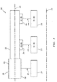
- FIG. 1 is a schematic illustration an actuation system 20 with an actuation system centerline 22.
- This actuation system 20 includes a plurality of components 24-26 disposed along the actuation system centerline 22.
- the actuation system 20 also includes a linear actuator 28; e.g., a dual lead screw actuator.
- the components may include a stationary (e.g., axially forward) component 24, a first translatable (e.g., axially intermediate) component 25 and a second translatable (e.g., axially aft) component 26.
- These components 24-26 may be configured as components of a turbofan turbine engine aircraft propulsion system.
- the stationary component 24 may be configured as a torque box for a thrust reverser system, or any other stationary component of a forward nacelle structure.
- the translatable components 25 and 26 may be configured as aft translatable components of the thrust reverser system.
- translatable components include, but are not limited to, a translating sleeve, a translating cascade and a translating support structure (e.g., a blocker door carriage).
- One of the translatable components may alternatively be configured as another type of aft translatable component; e.g., a translating nozzle for a variable area fan nozzle (VAFN).
- VAFN variable area fan nozzle
- Other examples of stationary and translatable components are disclosed in U.S. Application No. 14/968,357 and Attorney Docket No. 93671US01. The components of the present disclosure, however, are not limited to the foregoing exemplary configurations.
- the actuation system 20 of the present disclosure is not limited to aircraft propulsion system applications.
- the linear actuator 28 extends longitudinally along an actuation axis 30, which is substantially parallel to the actuation system centerline 22. This linear actuator 28 is configured to translate the first translatable component 25 axially along the actuation system centerline 22. The linear actuator 28 is also configured to translate the second translatable component 26 axially along the actuation system centerline 22.
- the linear actuator 28 includes a stationary actuator base 32, a first translatable element 34 (e.g., a carriage) and a second translatable element 36 (e.g., a carriage, or rod end), which elements are disposed along the actuation axis 30.
- the actuator base 32 is mounted to the stationary component 24.
- the first translatable element 34 is mounted to the first translatable component 25.
- the second translatable element 36 is mounted to the second translatable component 26.
- the linear actuator 28 also includes a drive mechanism 38 (e.g., a dual lead screw, a dual piston, etc.) and an actuation device 40; e.g., a motor.
- the actuation device 40 may be configured as an electric motor, a hydraulic actuation device, a pneumatic actuation device, or any other type of actuation device.
- the actuation device 40 is configured to drive each of the translatable elements 34 and 36 (at the same or different speeds) along the actuation axis 30 through the drive mechanism 38.
- An example of such a linear actuator is disclosed in the U.S. Application No. 14/968,357 referenced above.
- the actuation system 20 of the present disclosure is not limited to such an exemplary drive mechanism or linear actuator.
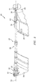
- the elements 32, 34 and 36 of the linear actuator 28 are mounted to the components 24-26 through respective mounting structures 42-44.
- the first mounting structure 42 may be configured as a gimbal joint. This gimbal joint configuration enables the actuator base 32 to pivot relative to the stationary component 24 about a pivot axis 46 and a pivot axis 46A.
- the pivot axis 46 is substantially perpendicular to the actuation axis 30.
- the pivot axis 46 may also be coincident with (e.g., cross-through) the actuation axis 30 and the actuation system centerline 22 (see FIG. 1 ).
- the present disclosure is not limited to such an exemplary first mounting structure configuration.
- the third mounting structure 44 may be configured as a spherical bearing joint.
- the third mounting structure 44 may include a rod end 48 with a spherical bearing and a pair of mounting tabs 50, which are connect to (e.g., formed integral with or otherwise attached to) and project out from the second translatable component 26.
- the spherical bearing is disposed between and mechanically fastened to the mounting tabs 50.
- the spherical bearing enables the second translatable element 36 to pivot about a centroid of the bearing in two orthogonal directions.
- the present disclosure is not limited to such an exemplary third mounting structure configuration.
- the second mounting structure 43 may be configured as a five degree-of-freedom (5DoF) joint.
- This 5DoF joint configuration may enable at least slight movement of the first translatable element 34 relative to the first translatable component 25 in all but an axial (relative to the actuation axis 30) direction.
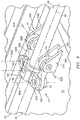
- the second mounting structure 43 includes an actuator mount 52, a pair of link mounts 54A and 54B, and a pair of links 56A and 56B (e.g., struts).
- the actuator mount 52 includes a mount base 58 and a pair of link mounts 60A and 60B.
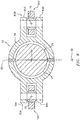
- the mount base 58 may have a generally tubular body, which extends circumferentially completely (or partially) around the first translatable element 34 and the actuation axis 30.
- This mount base 58 is configured as a gimbal joint, and is pivotally connected to the first translatable element 34 about a pivot axis 62.
- the pivot axis 62 is substantially perpendicular to the actuation axis 30.
- the pivot axis 62 may also be coincident with (e.g., cross-through) the actuation axis 30 and the actuation system centerline 22 (see FIG. 6 ).
- each of the link mounts 60A, 60B may include a pair of parallel mounting tabs 64A, 64B.
- the first pair of mounting tabs 64A are disposed on a lateral first side of the linear actuator 28. These mounting tabs 64A project laterally out from the mount base 58.
- the second pair of mounting tabs 64B are disposed on a lateral second side of the linear actuator 28, which second side is laterally opposite the first side.
- the mounting tabs 64B project laterally out from the mount base 58.
- each of the link mounts 54A, 54B may include a pair of parallel mounting tabs 66A, 66B.
- This first pair of mounting tabs 66A are disposed on the first side of the linear actuator 28. These mounting tabs 66A project out from and are connected to the first translatable component 25.
- the second pair of mounting tabs 66B are disposed on the second side of the linear actuator 28. These mounting tabs 66B project laterally out from and are connected to the first translatable component 25.
- the first link 56A is disposed on the first side of the linear actuator 28.
- the second link 56B is disposed on the second side of the linear actuator 28.
- the first link 56A and the second link 56B may have substantially identical configurations.
- Each link 56 of FIGS. 5 and 7 includes a unitary structural member 68 that extends along a centerline 70 between opposing link ends 72 and 74.
- Each link 56 also includes a pair of spherical bearings 76 and 78.
- the centerline 70 of the structural member 68 may have a straight-line trajectory that extends through centroids of the spherical bearings 76 and 78, where the centerline 70 is substantially parallel to the actuation axis 30.
- the first spherical bearing 76 is arranged with the structural member 68 at the first link end 72.
- the first spherical bearing 76 is disposed between and mechanically fastened to a respective pair of the mounting tabs 64A, 64B and its mount 60A, 60B; see also FIG. 6 .
- This first spherical bearing 76 has an axis 80A, 80B (e.g., a central bore / pivot axis), which extends through its centroid.
- This axis 80 is substantially perpendicular to the actuation axis 30 and substantially parallel to the pivot axis 62.
- the axes 80 of the pair of links 56 are also parallel with one another.
- the second spherical bearing 78 is arranged with the structural member 68 at the second link end 74.
- the second spherical bearing 78 is disposed between and mechanically fastened to a respective pair of the mounting tabs 66A, 66B.
- This second spherical bearing 78 has an axis 82A, 82B (e.g., a central bore / pivot axis), which extends through its centroid.
- This axis 82 is substantially perpendicular to the actuation axis 30 and to the axes 80 and 62 and 30.
- the axes 82 of the pair of links 56 are also parallel with one another and, here, also co-axial with one another.
- the components 24-26 may shift relative to one another, where this shifting represents movement different from the axial translation of the components 25 and 26.
- this shifting may be in the form of slight rotation about the actuation system centerline 22.
- This shifting may be also or alternatively be in the form of slight radial movement relative to the actuation system centerline 22. This can lead to the linear actuator 28 and its actuation axis 30 being slightly skewed from the actuation system centerline 22.
- the second mounting structure 43 is operable to allow slight misalignment between the first translatable component 25 and the first translatable element 34 while also significantly reducing or substantially eliminating transmission of non-axial (e.g., lateral, radial, etc.) loads between the elements 25 and 34.
- the second mounting structure 43 may be operable to substantially only transmits axial loads between the first translatable element 34 and the first translatable component 25; e.g., along the centerlines 70 (see FIG. 7 ).
- the afore-described operability of the second mounting structure 43 is enabled by, among other things, the link centerlines 70 being substantially parallel to the actuation axis 30.
- links 800 are non-parallel to an actuation axis 802 as shown in FIG. 8 , these links 800 transmit a radial load between components 804 and 806.
- the actuation system 20 of the present disclosure may have different configurations than that described above.
- one of the components 25 or 26 may be omitted, and the mounting structure 43 may be used to mount the linear actuator 28 to the remaining one of the components 25, 26.
- one or more of the spherical bearings 76 and/or 78 may each be configured with a respective one of the mounts 54, 60, and mechanically fastened to the link 56; e.g., the coupling arrangement between the mounts and the links may be reversed.
- the present disclosure therefore is not limited to the exemplary embodiments described above and illustrated in the drawings.
Landscapes
- Engineering & Computer Science (AREA)
- General Engineering & Computer Science (AREA)
- Mechanical Engineering (AREA)
- Chemical & Material Sciences (AREA)
- Combustion & Propulsion (AREA)
- Manipulator (AREA)
- Transmission Devices (AREA)
- Reciprocating, Oscillating Or Vibrating Motors (AREA)
Claims (14)
- Betätigungssystem (20), umfassend:ein Bauteil (24; 25; 26);einen Linearaktuator (28), der sich in Längsrichtung entlang einer Betätigungsachse (30) erstreckt;ein erstes Verbindungsstück (56A), das sich entlang einer ersten Mittellinie (70) parallel zur Betätigungsachse (30) erstreckt, wobei das erste Verbindungsstück (56A) an einer ersten Seite des Linearaktuators (28) angeordnet ist; undein zweites Verbindungsstück (56B), das sich entlang einer zweiten Mittellinie (70) parallel zur Betätigungsachse (30) erstreckt, wobei das zweite Verbindungsstück (56B) an einer zweiten Seite des Linearaktuators (28) seitlich gegenüber der ersten Seite angeordnet ist;wobei das erste und das zweite Verbindungsstück (56A, B) so konfiguriert sind, dass sie eine Last entlang der ersten und der zweiten Mittellinie (70) zwischen dem Bauteil (24; 25; 26) und dem Linearaktuator (28) übertragen;dadurch gekennzeichnet, dass:das System (20) ferner ein zweites Bauteil (25) umfasst;der Linearaktuator (28) eine Aktuatorbasis (32) und ein verschiebbares Element (34) beinhaltet, wobei der Linearaktuator (28) so konfiguriert ist, dass er das verschiebbare Element (34) relativ zur Aktuatorbasis (32) bewegt;die Aktuatorbasis (32) mit dem zweiten Bauteil (25) gekoppelt ist; unddas verschiebbare Element (34) mit dem zweiten Bauteil (25) über das erste und das zweite Verbindungsstück (56A, B) gekoppelt ist.
- Betätigungssystem nach Anspruch 1, wobei
das erste Verbindungsstück (56A) ein erstes Sphärolager (78) und ein zweites Sphärolager (76) beinhaltet; und sich das erste Verbindungsstück (56A) entlang der ersten Mittellinie (70) zwischen dem ersten Sphärolager (78) und dem zweiten Sphärolager (76) erstreckt. - Betätigungssystem nach Anspruch 2, ferner umfassend ein Paar Befestigungslaschen (50; 66A, B), die aus dem Bauteil (24) vorragen, wobei das erste Sphärolager (78) seitlich zwischen den Befestigungslaschen (50; 66A, B) liegt und an diesen fixiert ist.
- Betätigungssystem nach Anspruch 2, ferner umfassend eine Aktuatorhalterung (52), die schwenkbar an dem Linearaktuator (28) fixiert ist, wobei die Aktuatorhalterung (52) ein Paar Befestigungslaschen (64A, B) beinhaltet und das zweite Sphärolager (76) seitlich zwischen den Befestigungslaschen (64A, B) liegt und an diesen fixiert ist.
- Betätigungssystem nach Anspruch 4, ferner umfassend ein Paar zweiter Befestigungslaschen (50; 66A, B), die aus dem Bauteil (24) vorragen, wobei das erste Sphärolager (78) seitlich zwischen den zweiten Befestigungslaschen (50; 66A, B) liegt und an diesen fixiert ist.
- Betätigungssystem nach einem der Ansprüche 2 bis 5, wobei das erste Sphärolager (78) eine erste Achse (80; 80A, B) aufweist, das zweite Sphärolager (76) eine zweite Achse (82; 82A, B) aufweist und die erste Achse (80; 80A, B) senkrecht zur zweiten Achse (82; 82A, B) ist.
- Betätigungssystem nach Anspruch 6, wobei die erste Achse (80; 80A, B) und die zweite Achse (82; 82A, B) senkrecht zur Betätigungsachse (30) sind.
- Betätigungssystem nach Anspruch 1, ferner Folgendes umfassend:eine Aktuatorhalterung (52), die eine Halterungsbasis (58), eine erste Halterung (60A) und eine zweite Halterung (60B) beinhaltet, wobei sich die Halterungsbasis (58) in Umfangsrichtung um den Linearaktuator (28) erstreckt und schwenkbar mit diesem gekoppelt ist, die erste Halterung (60A) an der ersten Seite liegt und radial aus der Halterungsbasis (58) vorragt und die zweite Halterung (60B) an der zweiten Seite liegt und radial aus der Halterungsbasis (58) vorragt;ein erstes Sphärolager (76), das die erste Halterung (60A) mit dem ersten Verbindungsstück (56A) koppelt; undein zweites Sphärolager (76), das die zweite Halterung (60B) mit dem zweiten Verbindungsstück (56B) koppelt.
- Betätigungssystem nach Anspruch 8, ferner umfassend:eine dritte Halterung (54A), die mit dem Bauteil (25) verbunden ist;eine vierte Halterung (54B), die mit dem Bauteil (25) verbunden ist;ein drittes Sphärolager (78), das die dritte Halterung (54A) mit dem ersten Verbindungsstück (56A) koppelt;und ein viertes Sphärolager (78), das die vierte Halterung (54B) mit dem zweiten Verbindungsstück (56B) koppelt.
- Betätigungssystem nach Anspruch 9, wobei sich die erste Mittellinie (70) durch einen Schwerpunkt des ersten Sphärolagers (76) und einen Schwerpunkt des dritten Sphärolagers (78) erstreckt.
- Betätigungssystem nach einem der Ansprüche 8 bis 10, wobei die Halterungsbasis (58) schwenkbar an den Linearaktuator (28) um eine Schwenkachse (62) senkrecht zur Betätigungsachse (30) gekoppelt ist.
- Betätigungssystem nach Anspruch 1, ferner umfassend:eine erste Halterung (60A), die mit dem Bauteil (25) verbunden ist;eine zweite Halterung (60B), die mit dem Bauteil (25) verbunden ist;ein erstes Sphärolager (76), das die erste Halterung (60A) mit dem ersten Verbindungsstück (56A) koppelt; undein zweites Sphärolager (76), das die zweite Halterung (60B) mit dem zweiten Verbindungsstück (56B) koppelt.
- Betätigungssystem nach einem der vorstehenden Ansprüche, ferner umfassend:ein drittes Bauteil (26);wobei das zweite Bauteil (25) axial zwischen dem Bauteil (24) und dem dritten Bauteil (26) entlang der Betätigungsachse (30) angeordnet ist;wobei der Linearaktuator (28) ein zweites verschiebbares Element (36) beinhaltet, wobei der Linearaktuator (28) so konfiguriert ist, dass er das zweite verschiebbare Element (36) relativ zur Aktuatorbasis (32) bewegt; undwobei das zweite verschiebbare Element (36) an das dritte Bauteil (26) gekoppelt ist.
- Betätigungssystem nach einem der vorstehenden Ansprüche, wobei das Bauteil (24; 25; 26) als ein Bauteil eines Gondelsystems konfiguriert ist.
Applications Claiming Priority (1)
| Application Number | Priority Date | Filing Date | Title |
|---|---|---|---|
| US15/188,565 US9976696B2 (en) | 2016-06-21 | 2016-06-21 | Linear actuator with multi-degree of freedom mounting structure |
Publications (2)
| Publication Number | Publication Date |
|---|---|
| EP3301326A1 EP3301326A1 (de) | 2018-04-04 |
| EP3301326B1 true EP3301326B1 (de) | 2020-11-18 |
Family
ID=59296667
Family Applications (1)
| Application Number | Title | Priority Date | Filing Date |
|---|---|---|---|
| EP17176360.0A Active EP3301326B1 (de) | 2016-06-21 | 2017-06-16 | Linearaktuator mit montagestruktur mit mehreren freiheitsgraden |
Country Status (2)
| Country | Link |
|---|---|
| US (1) | US9976696B2 (de) |
| EP (1) | EP3301326B1 (de) |
Families Citing this family (5)
| Publication number | Priority date | Publication date | Assignee | Title |
|---|---|---|---|---|
| EP3267034B1 (de) * | 2016-07-07 | 2020-05-13 | Cameron Technologies Limited | Selbstausrichtende schlammpumpenanordnung |
| US11208970B2 (en) * | 2018-06-28 | 2021-12-28 | Rohr, Inc. | Aft cascade ring design concept |
| RU2734328C2 (ru) * | 2018-08-06 | 2020-10-15 | Акционерное общество "Объединенная двигателестроительная корпорация" (АО "ОДК") | Устройство привода сдвижки реверсивного устройства газотурбинного двигателя |
| CA3116295A1 (en) * | 2018-10-17 | 2020-04-23 | Airbus Defence And Space, S.A. | Articulated mechanism and articulated pointing system comprising that mechanism |
| FR3105304B1 (fr) * | 2019-12-19 | 2021-12-10 | Safran Nacelles | Inverseur de poussée avec système d’actionnement anti-flambage |
Family Cites Families (85)
| Publication number | Priority date | Publication date | Assignee | Title |
|---|---|---|---|---|
| BE562528A (de) | 1956-11-21 | |||
| GB913699A (de) | 1959-12-18 | |||
| GB1150012A (en) | 1966-09-12 | 1969-04-30 | Rolls Royce | Fluid Flow Duct Including Thrust Reversing Means |
| US3500646A (en) | 1968-04-19 | 1970-03-17 | Rohr Corp | Thrust reverser |
| US3511055A (en) | 1968-05-29 | 1970-05-12 | Rohr Corp | Thrust reverser |
| BE755612A (fr) | 1969-06-18 | 1971-02-15 | Gen Electric | Tuyeres de propulsion a systeme suppresseur de bruit ameliore |
| US3621763A (en) | 1969-07-17 | 1971-11-23 | Pneumo Dynamics Corp | Fan thrust reverser actuator |
| US3612209A (en) | 1969-11-28 | 1971-10-12 | Gen Electric | Propulsion nozzle with combined thrust reverser and sound suppressor mechanism |
| US3600894A (en) | 1970-04-28 | 1971-08-24 | Rohr Corp | Thrust reversing apparatus |
| US3829020A (en) | 1973-06-13 | 1974-08-13 | Boeing Co | Translating sleeve variable area nozzle and thrust reverser |
| US4278220A (en) | 1979-03-30 | 1981-07-14 | The United States Of America As Represented By The Administrator Of The National Aeronautics And Space Administration | Thrust reverser for a long duct fan engine |
| US4465392A (en) * | 1981-06-12 | 1984-08-14 | The United States Of America As Represented By The Secretary Of The Air Force | Thermally isolated structural support link |
| US4564160A (en) | 1982-09-29 | 1986-01-14 | The Boeing Company | Thrust reverser blocker door assembly |
| WO1984001446A1 (en) | 1982-09-30 | 1984-04-12 | Boeing Co | Modular multi-engine thrust control assembly |
| US4519561A (en) | 1983-05-23 | 1985-05-28 | Rohr Industries, Inc. | Aircraft thrust reverser mechanism |
| US4909442A (en) | 1984-05-14 | 1990-03-20 | The Boeing Company | Actuation system for a blocker door in a jet engine nacelle |
| US4688446A (en) * | 1985-03-04 | 1987-08-25 | Union Special Corporation | Connecting rod manufacture |
| US4807434A (en) | 1987-12-21 | 1989-02-28 | The Boeing Company | Thrust reverser for high bypass jet engines |
| US5117630A (en) | 1990-02-12 | 1992-06-02 | Rohr Industries, Inc. | Pivoting door thrust reverser |
| US5228641A (en) | 1991-08-15 | 1993-07-20 | Rohr, Inc. | Cascade type aircraft engine thrust reverser with hidden link actuator |
| US5309711A (en) | 1991-08-21 | 1994-05-10 | Rohr, Inc. | Cascade type thrust reverser for fan jet engines |
| US5255850A (en) | 1992-06-29 | 1993-10-26 | The United States Of America As Represented By The Secretary Of The Air Force | Pivoting flaps and vane pack in a nozzle reverser assembly |
| US5476237A (en) | 1993-06-18 | 1995-12-19 | Northrop Grumman Corporation | Syntactic film for thrust reverser blocker doors |
| US5778659A (en) | 1994-10-20 | 1998-07-14 | United Technologies Corporation | Variable area fan exhaust nozzle having mechanically separate sleeve and thrust reverser actuation systems |
| US5609020A (en) | 1995-05-15 | 1997-03-11 | The Boeing Company | Thrust reverser synchronization shaft lock |
| EP0801221A3 (de) | 1996-04-09 | 1998-11-04 | Lucas Industries Public Limited Company | Betätigungssystem für eine Schubumkehrvorrichtung eines Flugzeugs |
| US6036238A (en) | 1996-10-30 | 2000-03-14 | The Boeing Company | Double stroke over center latch |
| US5987880A (en) | 1997-07-08 | 1999-11-23 | Mcdonnell Douglas Corporation | Supersonic engine, multi-port thrust reversing system |
| US5927647A (en) | 1997-09-24 | 1999-07-27 | Rohr, Inc. | Blocker door frame pressure structure for translating cowl of cascade thrust reverser for aircraft jet engine |
| US6042053A (en) | 1997-10-31 | 2000-03-28 | The Boeing Company | Automatic restow system for aircraft thrust reverser |
| EP0926333A1 (de) | 1997-12-26 | 1999-06-30 | SOCIETE DE CONSTRUCTION DES AVIONS HUREL-DUBOIS (société anonyme) | Konfiguration einer Schubumkehrvorrichtung |
| GB9825651D0 (en) | 1998-11-23 | 1999-01-13 | Lucas Ind Plc | Actuator |
| US6170254B1 (en) | 1998-12-18 | 2001-01-09 | Rohr, Inc. | Translating sleeve for cascade type thrust reversing system for fan gas turbine engine for an aircraft |
| US6293495B1 (en) | 1999-12-08 | 2001-09-25 | Rohr, Inc. | Pivoting door thrust reverser system for turbofan aircraft jet engine |
| US6340135B1 (en) | 2000-05-30 | 2002-01-22 | Rohr, Inc. | Translating independently mounted air inlet system for aircraft turbofan jet engine |
| DE10124843A1 (de) | 2001-05-22 | 2002-11-28 | Ina Schaeffler Kg | Gleitlager |
| US6845945B1 (en) | 2001-07-20 | 2005-01-25 | Aircraft Integration Resources, Inc. | Thrust reverser with sliding pivot joints |
| US6584763B2 (en) | 2001-08-01 | 2003-07-01 | Rohr, Inc. | Lock for the translating sleeve of a turbofan engine thrust reverser |
| US6487846B1 (en) | 2001-09-07 | 2002-12-03 | Honeywell International, Inc. | Thrust reverser actuator including an integrated locking mechanism |
| BR0315201A (pt) | 2002-10-11 | 2005-08-16 | Nordam Group Inc | Inversor de impulsão de dobra dupla |
| US6845946B2 (en) | 2003-02-21 | 2005-01-25 | The Nordam Group, Inc. | Self stowing thrust reverser |
| US6976352B2 (en) | 2003-03-22 | 2005-12-20 | The Nordam Group, Inc. | Toggle interlocked thrust reverser |
| US7146796B2 (en) | 2003-09-05 | 2006-12-12 | The Nordam Group, Inc. | Nested latch thrust reverser |
| US7264203B2 (en) | 2003-10-02 | 2007-09-04 | The Nordam Group, Inc. | Spider actuated thrust reverser |
| US20060288688A1 (en) | 2005-06-22 | 2006-12-28 | Jean-Pierre Lair | Turbofan core thrust spoiler |
| US7513101B2 (en) | 2005-10-28 | 2009-04-07 | Honeywell International Inc. | Synchronized motor thrust reverser actuation system |
| GB0606982D0 (en) | 2006-04-07 | 2006-05-17 | Rolls Royce Plc | Aeroengine thrust reverser |
| EP2074320B1 (de) | 2006-10-12 | 2013-06-26 | United Technologies Corporation | Gebläsedüsen-schubumkehrvorrichtung mit variablem querschnitt |
| FR2907512B1 (fr) | 2006-10-23 | 2008-12-12 | Aircelle Sa | Inverseur de poussee a grilles pour moteur a reaction |
| FR2917788B1 (fr) | 2007-06-19 | 2009-07-24 | Aircelle Sa | Actionneur double action a effet programme |
| FR2922059B1 (fr) | 2007-10-04 | 2014-07-04 | Aircelle Sa | Actionneur lineaire telescopique double action a systeme d'entrainement a moteur unique |
| FR2922058B1 (fr) | 2007-10-04 | 2009-12-04 | Aircelle Sa | Actionneur lineaire telescopique pour deplacer un premier et un second elements relativement a un element fixe |
| FR2921976B1 (fr) | 2007-10-08 | 2009-12-04 | Aircelle Sa | Actionneur pour structure mobile de nacelle d'aeronef, et nacelle comprenant au moins un tel actionneur |
| US7735778B2 (en) | 2007-11-16 | 2010-06-15 | Pratt & Whitney Canada Corp. | Pivoting fairings for a thrust reverser |
| US8002217B2 (en) | 2007-11-16 | 2011-08-23 | Spirit Aerosystems, Inc. | System for adjustment of thrust reverser pivot door |
| US8172175B2 (en) | 2007-11-16 | 2012-05-08 | The Nordam Group, Inc. | Pivoting door thrust reverser for a turbofan gas turbine engine |
| US8109466B2 (en) | 2008-06-23 | 2012-02-07 | Rohr, Inc. | Thrust reverser cascade assembly and AFT cascade ring with flow deflector portion |
| FR2933144B1 (fr) | 2008-06-26 | 2012-08-17 | Airbus France | Nacelle pour aeronef comportant des moyens inverseurs de poussee et aeronef comportant au moins une telle nacelle |
| US8109467B2 (en) | 2009-04-24 | 2012-02-07 | United Technologies Corporation | Thrust reverser assembly with shaped drag links |
| FR2946094B1 (fr) | 2009-06-02 | 2014-04-18 | Aircelle Sa | Inverseur de poussee pour nacelle de turboreacteur double flux. |
| FR2946696B1 (fr) | 2009-06-10 | 2012-04-20 | Aircelle Sa | Dispositif d'inversion de poussee |
| US8322653B2 (en) | 2009-09-11 | 2012-12-04 | Spirit Aerosystems, Inc. | Hybrid beam for a thrust reverser unit |
| FR2952128B1 (fr) | 2009-11-05 | 2011-11-04 | Aircelle Sa | Dispositif d'inverseur de poussee |
| FR2954409A1 (fr) | 2009-12-18 | 2011-06-24 | Aircelle 7298 | Dispositif d'inverseur de poussee |
| US8869507B2 (en) | 2010-01-13 | 2014-10-28 | United Technologies Corporation | Translatable cascade thrust reverser |
| FR2966434B1 (fr) * | 2010-10-21 | 2013-05-31 | Sagem Defense Securite | Systeme d'actionnement pour un ensemble de propulsion d'un avion |
| DE102011008918A1 (de) | 2011-01-19 | 2012-07-19 | Rolls-Royce Deutschland Ltd & Co Kg | Fluggasturbinenschubumkehrvorrichtung |
| US20120187214A1 (en) | 2011-01-25 | 2012-07-26 | Spirit Aerosystems, Inc. | Converging blocker door system for use with a thrust reverser |
| US8720183B2 (en) | 2011-03-02 | 2014-05-13 | Spirit Aerosystems, Inc. | Thrust reverser translating sleeve assembly |
| US8479491B2 (en) | 2011-06-06 | 2013-07-09 | General Electric Company | Clamping system and method for thrust reverser attachment |
| US8615982B2 (en) | 2011-07-05 | 2013-12-31 | Hamilton Sundstrand Corporation | Integrated electric variable area fan nozzle thrust reversal actuation system |
| FR2978516B1 (fr) * | 2011-07-29 | 2013-08-02 | Aircelle Sa | Actionneur lineaire double action |
| US9181898B2 (en) | 2011-09-20 | 2015-11-10 | United Technologies Corporation | Thrust reverser for a gas turbine engine with moveable doors |
| US8876390B2 (en) * | 2011-12-14 | 2014-11-04 | Roller Bearing Company Of America, Inc. | Slotted bearings with wear-resistant treatments for gearbox mounting in a geared turbofan engine |
| US9316112B2 (en) | 2011-12-21 | 2016-04-19 | Rohr, Inc. | Variable area fan nozzle with drive system health monitoring |
| US9086035B2 (en) | 2012-01-20 | 2015-07-21 | Hamilton Sundstrand Corporation | Integrated thrust reverser actuator and variable area fan nozzle actuator |
| US8904751B2 (en) | 2012-04-30 | 2014-12-09 | Middle River Aircraft Systems | Thrust reverser assembly and method of operation |
| US9303590B2 (en) | 2012-05-22 | 2016-04-05 | Spirit Aerosystems, Inc. | Variable area fan nozzle actuation system |
| US9016040B2 (en) | 2012-11-30 | 2015-04-28 | General Electric Company | Thrust reverser system with translating-rotating cascade and method of operation |
| FR3002593B1 (fr) | 2013-02-25 | 2015-03-27 | Aircelle Sa | Actionneur pour nacelle de turboreacteur d'aeronef |
| US9388768B2 (en) | 2013-08-23 | 2016-07-12 | Rohr, Inc. | Blocker door actuation system and apparatus |
| US9260194B2 (en) | 2013-10-24 | 2016-02-16 | Rohr, Inc. | Gimbal pin for jet propulsion system |
| US9278752B2 (en) * | 2014-03-17 | 2016-03-08 | Lockheed Martin Corporation | Apparatus and system for preventing wear to a component |
| US9938929B2 (en) | 2014-03-21 | 2018-04-10 | Rohr, Inc. | Thrust reverser for a turbofan engine |
| US9534562B2 (en) | 2014-04-25 | 2017-01-03 | Rohr, Inc. | System and apparatus for a thrust reverser |
-
2016
- 2016-06-21 US US15/188,565 patent/US9976696B2/en active Active
-
2017
- 2017-06-16 EP EP17176360.0A patent/EP3301326B1/de active Active
Non-Patent Citations (1)
| Title |
|---|
| None * |
Also Published As
| Publication number | Publication date |
|---|---|
| US9976696B2 (en) | 2018-05-22 |
| US20170363250A1 (en) | 2017-12-21 |
| EP3301326A1 (de) | 2018-04-04 |
Similar Documents
| Publication | Publication Date | Title |
|---|---|---|
| EP3301326B1 (de) | Linearaktuator mit montagestruktur mit mehreren freiheitsgraden | |
| US8291782B1 (en) | Actuator assembly for stabilizers | |
| EP3128196B1 (de) | Drehmomentrohranordnungen zur verwendung mit flugzeughochauftriebsvorrichtungen | |
| US7560888B2 (en) | Electromechanical actuator including redundant, dissimilar position feedback | |
| EP3406888B1 (de) | Aktuator | |
| EP2175123A2 (de) | Regelungsvorrichtung und entsprechende Schubumkehrvorrichtung | |
| US10527142B2 (en) | Hydraulic rotary ball screw actuator | |
| CN110053762B (zh) | 转矩管组件及组装转矩管组件的方法 | |
| EP3514054B1 (de) | Vorrichtung und verfahren zum aufrüsten einer drehröhrenanordnung in einem flugzeug | |
| US11815179B2 (en) | Actuator for transmission | |
| US9932105B2 (en) | Device for folding/unfolding a tail boom of a rotorcraft, an associated rotorcraft, and a corresponding folding/unfolding method | |
| US5102050A (en) | Divergent flap actuation system for two-dimensional convergent - divergent turbojet exhaust nozzle | |
| EP2628935A2 (de) | Aktuatoranordnung | |
| EP4160048B1 (de) | Kugelgewinde-drehantrieb mit kugelkäfig | |
| EP3534038B1 (de) | Aktuator mit doppelter stange und exzenterkupplung | |
| US5934564A (en) | Variable geometry turbojet engine exhaust nozzle | |
| RU2733031C2 (ru) | Универсальный шарнир | |
| EP3282132B1 (de) | Aktuator mit einer kupplung | |
| US20180155010A1 (en) | Control system for an actuator | |
| EP3951155B1 (de) | Betätigungssystem für einen schubumkehrer eines flugzeugantriebssystems | |
| US4838104A (en) | Center mounted and center drive helical spline actuator | |
| US20250145276A1 (en) | Linear actuator for a flight control surface | |
| KR101772277B1 (ko) | 항공기용 착륙장치 |
Legal Events
| Date | Code | Title | Description |
|---|---|---|---|
| PUAI | Public reference made under article 153(3) epc to a published international application that has entered the european phase |
Free format text: ORIGINAL CODE: 0009012 |
|
| STAA | Information on the status of an ep patent application or granted ep patent |
Free format text: STATUS: THE APPLICATION HAS BEEN PUBLISHED |
|
| AK | Designated contracting states |
Kind code of ref document: A1 Designated state(s): AL AT BE BG CH CY CZ DE DK EE ES FI FR GB GR HR HU IE IS IT LI LT LU LV MC MK MT NL NO PL PT RO RS SE SI SK SM TR |
|
| AX | Request for extension of the european patent |
Extension state: BA ME |
|
| STAA | Information on the status of an ep patent application or granted ep patent |
Free format text: STATUS: REQUEST FOR EXAMINATION WAS MADE |
|
| 17P | Request for examination filed |
Effective date: 20181004 |
|
| RBV | Designated contracting states (corrected) |
Designated state(s): AL AT BE BG CH CY CZ DE DK EE ES FI FR GB GR HR HU IE IS IT LI LT LU LV MC MK MT NL NO PL PT RO RS SE SI SK SM TR |
|
| GRAP | Despatch of communication of intention to grant a patent |
Free format text: ORIGINAL CODE: EPIDOSNIGR1 |
|
| STAA | Information on the status of an ep patent application or granted ep patent |
Free format text: STATUS: GRANT OF PATENT IS INTENDED |
|
| RIC1 | Information provided on ipc code assigned before grant |
Ipc: F16C 11/06 20060101ALI20200520BHEP Ipc: F15B 15/14 20060101ALI20200520BHEP Ipc: F16H 25/20 20060101AFI20200520BHEP Ipc: F02K 1/76 20060101ALI20200520BHEP |
|
| INTG | Intention to grant announced |
Effective date: 20200617 |
|
| RIN1 | Information on inventor provided before grant (corrected) |
Inventor name: GORMLEY, TIMOTHY |
|
| GRAS | Grant fee paid |
Free format text: ORIGINAL CODE: EPIDOSNIGR3 |
|
| GRAA | (expected) grant |
Free format text: ORIGINAL CODE: 0009210 |
|
| STAA | Information on the status of an ep patent application or granted ep patent |
Free format text: STATUS: THE PATENT HAS BEEN GRANTED |
|
| AK | Designated contracting states |
Kind code of ref document: B1 Designated state(s): AL AT BE BG CH CY CZ DE DK EE ES FI FR GB GR HR HU IE IS IT LI LT LU LV MC MK MT NL NO PL PT RO RS SE SI SK SM TR |
|
| REG | Reference to a national code |
Ref country code: GB Ref legal event code: FG4D |
|
| REG | Reference to a national code |
Ref country code: CH Ref legal event code: EP |
|
| REG | Reference to a national code |
Ref country code: IE Ref legal event code: FG4D |
|
| REG | Reference to a national code |
Ref country code: DE Ref legal event code: R096 Ref document number: 602017027633 Country of ref document: DE |
|
| REG | Reference to a national code |
Ref country code: AT Ref legal event code: REF Ref document number: 1336119 Country of ref document: AT Kind code of ref document: T Effective date: 20201215 |
|
| REG | Reference to a national code |
Ref country code: AT Ref legal event code: MK05 Ref document number: 1336119 Country of ref document: AT Kind code of ref document: T Effective date: 20201118 |
|
| REG | Reference to a national code |
Ref country code: NL Ref legal event code: MP Effective date: 20201118 |
|
| PG25 | Lapsed in a contracting state [announced via postgrant information from national office to epo] |
Ref country code: FI Free format text: LAPSE BECAUSE OF FAILURE TO SUBMIT A TRANSLATION OF THE DESCRIPTION OR TO PAY THE FEE WITHIN THE PRESCRIBED TIME-LIMIT Effective date: 20201118 Ref country code: GR Free format text: LAPSE BECAUSE OF FAILURE TO SUBMIT A TRANSLATION OF THE DESCRIPTION OR TO PAY THE FEE WITHIN THE PRESCRIBED TIME-LIMIT Effective date: 20210219 Ref country code: NO Free format text: LAPSE BECAUSE OF FAILURE TO SUBMIT A TRANSLATION OF THE DESCRIPTION OR TO PAY THE FEE WITHIN THE PRESCRIBED TIME-LIMIT Effective date: 20210218 Ref country code: PT Free format text: LAPSE BECAUSE OF FAILURE TO SUBMIT A TRANSLATION OF THE DESCRIPTION OR TO PAY THE FEE WITHIN THE PRESCRIBED TIME-LIMIT Effective date: 20210318 Ref country code: RS Free format text: LAPSE BECAUSE OF FAILURE TO SUBMIT A TRANSLATION OF THE DESCRIPTION OR TO PAY THE FEE WITHIN THE PRESCRIBED TIME-LIMIT Effective date: 20201118 |
|
| PG25 | Lapsed in a contracting state [announced via postgrant information from national office to epo] |
Ref country code: SE Free format text: LAPSE BECAUSE OF FAILURE TO SUBMIT A TRANSLATION OF THE DESCRIPTION OR TO PAY THE FEE WITHIN THE PRESCRIBED TIME-LIMIT Effective date: 20201118 Ref country code: BG Free format text: LAPSE BECAUSE OF FAILURE TO SUBMIT A TRANSLATION OF THE DESCRIPTION OR TO PAY THE FEE WITHIN THE PRESCRIBED TIME-LIMIT Effective date: 20210218 Ref country code: PL Free format text: LAPSE BECAUSE OF FAILURE TO SUBMIT A TRANSLATION OF THE DESCRIPTION OR TO PAY THE FEE WITHIN THE PRESCRIBED TIME-LIMIT Effective date: 20201118 Ref country code: LV Free format text: LAPSE BECAUSE OF FAILURE TO SUBMIT A TRANSLATION OF THE DESCRIPTION OR TO PAY THE FEE WITHIN THE PRESCRIBED TIME-LIMIT Effective date: 20201118 Ref country code: IS Free format text: LAPSE BECAUSE OF FAILURE TO SUBMIT A TRANSLATION OF THE DESCRIPTION OR TO PAY THE FEE WITHIN THE PRESCRIBED TIME-LIMIT Effective date: 20210318 Ref country code: AT Free format text: LAPSE BECAUSE OF FAILURE TO SUBMIT A TRANSLATION OF THE DESCRIPTION OR TO PAY THE FEE WITHIN THE PRESCRIBED TIME-LIMIT Effective date: 20201118 |
|
| REG | Reference to a national code |
Ref country code: LT Ref legal event code: MG9D |
|
| PG25 | Lapsed in a contracting state [announced via postgrant information from national office to epo] |
Ref country code: HR Free format text: LAPSE BECAUSE OF FAILURE TO SUBMIT A TRANSLATION OF THE DESCRIPTION OR TO PAY THE FEE WITHIN THE PRESCRIBED TIME-LIMIT Effective date: 20201118 |
|
| PG25 | Lapsed in a contracting state [announced via postgrant information from national office to epo] |
Ref country code: SK Free format text: LAPSE BECAUSE OF FAILURE TO SUBMIT A TRANSLATION OF THE DESCRIPTION OR TO PAY THE FEE WITHIN THE PRESCRIBED TIME-LIMIT Effective date: 20201118 Ref country code: RO Free format text: LAPSE BECAUSE OF FAILURE TO SUBMIT A TRANSLATION OF THE DESCRIPTION OR TO PAY THE FEE WITHIN THE PRESCRIBED TIME-LIMIT Effective date: 20201118 Ref country code: SM Free format text: LAPSE BECAUSE OF FAILURE TO SUBMIT A TRANSLATION OF THE DESCRIPTION OR TO PAY THE FEE WITHIN THE PRESCRIBED TIME-LIMIT Effective date: 20201118 Ref country code: LT Free format text: LAPSE BECAUSE OF FAILURE TO SUBMIT A TRANSLATION OF THE DESCRIPTION OR TO PAY THE FEE WITHIN THE PRESCRIBED TIME-LIMIT Effective date: 20201118 Ref country code: CZ Free format text: LAPSE BECAUSE OF FAILURE TO SUBMIT A TRANSLATION OF THE DESCRIPTION OR TO PAY THE FEE WITHIN THE PRESCRIBED TIME-LIMIT Effective date: 20201118 Ref country code: EE Free format text: LAPSE BECAUSE OF FAILURE TO SUBMIT A TRANSLATION OF THE DESCRIPTION OR TO PAY THE FEE WITHIN THE PRESCRIBED TIME-LIMIT Effective date: 20201118 |
|
| REG | Reference to a national code |
Ref country code: DE Ref legal event code: R097 Ref document number: 602017027633 Country of ref document: DE |
|
| PG25 | Lapsed in a contracting state [announced via postgrant information from national office to epo] |
Ref country code: DK Free format text: LAPSE BECAUSE OF FAILURE TO SUBMIT A TRANSLATION OF THE DESCRIPTION OR TO PAY THE FEE WITHIN THE PRESCRIBED TIME-LIMIT Effective date: 20201118 |
|
| PLBE | No opposition filed within time limit |
Free format text: ORIGINAL CODE: 0009261 |
|
| STAA | Information on the status of an ep patent application or granted ep patent |
Free format text: STATUS: NO OPPOSITION FILED WITHIN TIME LIMIT |
|
| 26N | No opposition filed |
Effective date: 20210819 |
|
| PG25 | Lapsed in a contracting state [announced via postgrant information from national office to epo] |
Ref country code: AL Free format text: LAPSE BECAUSE OF FAILURE TO SUBMIT A TRANSLATION OF THE DESCRIPTION OR TO PAY THE FEE WITHIN THE PRESCRIBED TIME-LIMIT Effective date: 20201118 Ref country code: NL Free format text: LAPSE BECAUSE OF FAILURE TO SUBMIT A TRANSLATION OF THE DESCRIPTION OR TO PAY THE FEE WITHIN THE PRESCRIBED TIME-LIMIT Effective date: 20201118 Ref country code: IT Free format text: LAPSE BECAUSE OF FAILURE TO SUBMIT A TRANSLATION OF THE DESCRIPTION OR TO PAY THE FEE WITHIN THE PRESCRIBED TIME-LIMIT Effective date: 20201118 |
|
| PG25 | Lapsed in a contracting state [announced via postgrant information from national office to epo] |
Ref country code: SI Free format text: LAPSE BECAUSE OF FAILURE TO SUBMIT A TRANSLATION OF THE DESCRIPTION OR TO PAY THE FEE WITHIN THE PRESCRIBED TIME-LIMIT Effective date: 20201118 |
|
| PG25 | Lapsed in a contracting state [announced via postgrant information from national office to epo] |
Ref country code: ES Free format text: LAPSE BECAUSE OF FAILURE TO SUBMIT A TRANSLATION OF THE DESCRIPTION OR TO PAY THE FEE WITHIN THE PRESCRIBED TIME-LIMIT Effective date: 20201118 Ref country code: MC Free format text: LAPSE BECAUSE OF FAILURE TO SUBMIT A TRANSLATION OF THE DESCRIPTION OR TO PAY THE FEE WITHIN THE PRESCRIBED TIME-LIMIT Effective date: 20201118 |
|
| REG | Reference to a national code |
Ref country code: CH Ref legal event code: PL |
|
| REG | Reference to a national code |
Ref country code: BE Ref legal event code: MM Effective date: 20210630 |
|
| PG25 | Lapsed in a contracting state [announced via postgrant information from national office to epo] |
Ref country code: LU Free format text: LAPSE BECAUSE OF NON-PAYMENT OF DUE FEES Effective date: 20210616 |
|
| PG25 | Lapsed in a contracting state [announced via postgrant information from national office to epo] |
Ref country code: LI Free format text: LAPSE BECAUSE OF NON-PAYMENT OF DUE FEES Effective date: 20210630 Ref country code: IE Free format text: LAPSE BECAUSE OF NON-PAYMENT OF DUE FEES Effective date: 20210616 Ref country code: CH Free format text: LAPSE BECAUSE OF NON-PAYMENT OF DUE FEES Effective date: 20210630 |
|
| PG25 | Lapsed in a contracting state [announced via postgrant information from national office to epo] |
Ref country code: IS Free format text: LAPSE BECAUSE OF FAILURE TO SUBMIT A TRANSLATION OF THE DESCRIPTION OR TO PAY THE FEE WITHIN THE PRESCRIBED TIME-LIMIT Effective date: 20210318 |
|
| PG25 | Lapsed in a contracting state [announced via postgrant information from national office to epo] |
Ref country code: BE Free format text: LAPSE BECAUSE OF NON-PAYMENT OF DUE FEES Effective date: 20210630 |
|
| PG25 | Lapsed in a contracting state [announced via postgrant information from national office to epo] |
Ref country code: HU Free format text: LAPSE BECAUSE OF FAILURE TO SUBMIT A TRANSLATION OF THE DESCRIPTION OR TO PAY THE FEE WITHIN THE PRESCRIBED TIME-LIMIT; INVALID AB INITIO Effective date: 20170616 |
|
| PG25 | Lapsed in a contracting state [announced via postgrant information from national office to epo] |
Ref country code: CY Free format text: LAPSE BECAUSE OF FAILURE TO SUBMIT A TRANSLATION OF THE DESCRIPTION OR TO PAY THE FEE WITHIN THE PRESCRIBED TIME-LIMIT Effective date: 20201118 |
|
| PG25 | Lapsed in a contracting state [announced via postgrant information from national office to epo] |
Ref country code: MK Free format text: LAPSE BECAUSE OF FAILURE TO SUBMIT A TRANSLATION OF THE DESCRIPTION OR TO PAY THE FEE WITHIN THE PRESCRIBED TIME-LIMIT Effective date: 20201118 |
|
| PG25 | Lapsed in a contracting state [announced via postgrant information from national office to epo] |
Ref country code: TR Free format text: LAPSE BECAUSE OF FAILURE TO SUBMIT A TRANSLATION OF THE DESCRIPTION OR TO PAY THE FEE WITHIN THE PRESCRIBED TIME-LIMIT Effective date: 20201118 |
|
| PG25 | Lapsed in a contracting state [announced via postgrant information from national office to epo] |
Ref country code: MT Free format text: LAPSE BECAUSE OF FAILURE TO SUBMIT A TRANSLATION OF THE DESCRIPTION OR TO PAY THE FEE WITHIN THE PRESCRIBED TIME-LIMIT Effective date: 20201118 |
|
| PGFP | Annual fee paid to national office [announced via postgrant information from national office to epo] |
Ref country code: DE Payment date: 20250520 Year of fee payment: 9 |
|
| PGFP | Annual fee paid to national office [announced via postgrant information from national office to epo] |
Ref country code: GB Payment date: 20250520 Year of fee payment: 9 |
|
| PGFP | Annual fee paid to national office [announced via postgrant information from national office to epo] |
Ref country code: FR Payment date: 20250520 Year of fee payment: 9 |
|
| P01 | Opt-out of the competence of the unified patent court (upc) registered |
Free format text: CASE NUMBER: UPC_APP_0017255_3301326/2025 Effective date: 20251211 |