EP3301331A2 - Schmiervorrichtung, die mit mehreren auffangbecken für die schmierflüssigkeit ausgestattet ist, und optimierte und zuverlässige weiterleitungsmittel zum haupttank - Google Patents
Schmiervorrichtung, die mit mehreren auffangbecken für die schmierflüssigkeit ausgestattet ist, und optimierte und zuverlässige weiterleitungsmittel zum haupttank Download PDFInfo
- Publication number
- EP3301331A2 EP3301331A2 EP17186759.1A EP17186759A EP3301331A2 EP 3301331 A2 EP3301331 A2 EP 3301331A2 EP 17186759 A EP17186759 A EP 17186759A EP 3301331 A2 EP3301331 A2 EP 3301331A2
- Authority
- EP
- European Patent Office
- Prior art keywords
- ejector
- lubricating liquid
- main
- lubricating
- lubrication
- Prior art date
- Legal status (The legal status is an assumption and is not a legal conclusion. Google has not performed a legal analysis and makes no representation as to the accuracy of the status listed.)
- Granted
Links
Images


Classifications
-
- F—MECHANICAL ENGINEERING; LIGHTING; HEATING; WEAPONS; BLASTING
- F16—ENGINEERING ELEMENTS AND UNITS; GENERAL MEASURES FOR PRODUCING AND MAINTAINING EFFECTIVE FUNCTIONING OF MACHINES OR INSTALLATIONS; THERMAL INSULATION IN GENERAL
- F16H—GEARING
- F16H57/00—General details of gearing
- F16H57/04—Features relating to lubrication or cooling or heating
- F16H57/0434—Features relating to lubrication or cooling or heating relating to lubrication supply, e.g. pumps; Pressure control
-
- B—PERFORMING OPERATIONS; TRANSPORTING
- B64—AIRCRAFT; AVIATION; COSMONAUTICS
- B64C—AEROPLANES; HELICOPTERS
- B64C27/00—Rotorcraft; Rotors peculiar thereto
- B64C27/04—Helicopters
- B64C27/12—Rotor drives
-
- F—MECHANICAL ENGINEERING; LIGHTING; HEATING; WEAPONS; BLASTING
- F16—ENGINEERING ELEMENTS AND UNITS; GENERAL MEASURES FOR PRODUCING AND MAINTAINING EFFECTIVE FUNCTIONING OF MACHINES OR INSTALLATIONS; THERMAL INSULATION IN GENERAL
- F16H—GEARING
- F16H57/00—General details of gearing
- F16H57/04—Features relating to lubrication or cooling or heating
- F16H57/0434—Features relating to lubrication or cooling or heating relating to lubrication supply, e.g. pumps; Pressure control
- F16H57/0436—Pumps
- F16H57/0438—Pumps of jet type, e.g. jet pumps with means to inject high pressure fluid to the suction area thereby supercharging the pump or means reducing cavitations
-
- F—MECHANICAL ENGINEERING; LIGHTING; HEATING; WEAPONS; BLASTING
- F16—ENGINEERING ELEMENTS AND UNITS; GENERAL MEASURES FOR PRODUCING AND MAINTAINING EFFECTIVE FUNCTIONING OF MACHINES OR INSTALLATIONS; THERMAL INSULATION IN GENERAL
- F16H—GEARING
- F16H57/00—General details of gearing
- F16H57/04—Features relating to lubrication or cooling or heating
- F16H57/0434—Features relating to lubrication or cooling or heating relating to lubrication supply, e.g. pumps; Pressure control
- F16H57/0443—Features relating to lubrication or cooling or heating relating to lubrication supply, e.g. pumps; Pressure control for supply of lubricant during tilt or high acceleration, e.g. problems related to the tilt or extreme acceleration of the transmission casing and the supply of lubricant under these conditions
-
- F—MECHANICAL ENGINEERING; LIGHTING; HEATING; WEAPONS; BLASTING
- F16—ENGINEERING ELEMENTS AND UNITS; GENERAL MEASURES FOR PRODUCING AND MAINTAINING EFFECTIVE FUNCTIONING OF MACHINES OR INSTALLATIONS; THERMAL INSULATION IN GENERAL
- F16H—GEARING
- F16H57/00—General details of gearing
- F16H57/04—Features relating to lubrication or cooling or heating
- F16H57/045—Lubricant storage reservoirs, e.g. reservoirs in addition to a gear sump for collecting lubricant in the upper part of a gear case
-
- F—MECHANICAL ENGINEERING; LIGHTING; HEATING; WEAPONS; BLASTING
- F16—ENGINEERING ELEMENTS AND UNITS; GENERAL MEASURES FOR PRODUCING AND MAINTAINING EFFECTIVE FUNCTIONING OF MACHINES OR INSTALLATIONS; THERMAL INSULATION IN GENERAL
- F16H—GEARING
- F16H57/00—General details of gearing
- F16H57/04—Features relating to lubrication or cooling or heating
- F16H57/0456—Lubrication by injection; Injection nozzles or tubes therefor
-
- F—MECHANICAL ENGINEERING; LIGHTING; HEATING; WEAPONS; BLASTING
- F16—ENGINEERING ELEMENTS AND UNITS; GENERAL MEASURES FOR PRODUCING AND MAINTAINING EFFECTIVE FUNCTIONING OF MACHINES OR INSTALLATIONS; THERMAL INSULATION IN GENERAL
- F16H—GEARING
- F16H57/00—General details of gearing
- F16H57/04—Features relating to lubrication or cooling or heating
- F16H57/0434—Features relating to lubrication or cooling or heating relating to lubrication supply, e.g. pumps; Pressure control
- F16H57/0442—Features relating to lubrication or cooling or heating relating to lubrication supply, e.g. pumps; Pressure control for supply in case of failure, i.e. auxiliary supply
Definitions
- the present invention relates to the field of lubrication of power transmission systems, particularly power transmission systems for a rotary wing aircraft.
- the present invention relates to a lubrication device provided with several lubricating liquid recovery tanks as well as optimized and reliable conveyance means to a main tank.
- This lubrication device is intended for the lubrication of a mechanical system and is particularly suitable for the lubrication of a power transmission system of a rotary wing aircraft, called "transmission system" thereafter.
- a mechanical system generally comprises rotating elements, such as shafts and bearings, as well as power transmission elements and reduction or increase of rotational speed, such as pinions and / or gears. It is therefore essential for the proper functioning of the mechanical system to lubricate and cool these elements, for example by a pressurized lubricating liquid such as oil.
- This lubrication is generally provided by a lubrication circuit and its main functions are to limit the wear and the heating of these elements of the mechanical system and, consequently, to prolong the life of the mechanical system. Without such lubrication, the operation of the mechanical system can be quickly degraded, if not impossible.
- This cooling circuit comprises for example a heat exchanger, such as an oil / air heat exchanger.
- a lubrication circuit also includes a flow generator such as a pump for supplying the lubrication circuit with the oil stored in a reservoir and thus allowing its circulation in the lubrication circuit.
- This tank is generally used as a recovery tank, the oil after lubrication of the mechanical system being recovered in this tank to feed the lubrication circuit again.
- a lubrication device of a mechanical system thus comprises a main lubrication circuit, a reservoir containing a lubricating liquid and a flow generator as well as possibly a cooling circuit.
- This reservoir is for example formed by the lower part of a housing containing this mechanical system.
- a lubrication device may also include a backup lubrication circuit to overcome a malfunction generating for example a drop or loss of pressure in the lubrication circuit. This pressure drop can be due to a failure of the flow generator or a leak in the main lubrication circuit or the cooling circuit.
- a backup lubrication circuit then makes it possible to ensure at least a lubrication of the essential organs of the mechanical system to ensure operation, possibly in degraded mode, of this mechanical system.
- This relief lubrication circuit then allows, when this system mechanical is for example a main power transmission of an aircraft, the operation of the aircraft to reach a landing place. Such an emergency lubrication circuit thus improves the safety of the aircraft.
- the main lubrication circuit and the emergency lubrication circuit can use the same reservoir containing the lubricating liquid.
- the backup lubrication circuit can also use a dedicated auxiliary tank, independent of a main tank used by the main lubrication circuit, as described in the document FR 2826094 .
- This auxiliary tank is in this case completely independent of the main lubrication circuit.
- the return of the lubricating liquid towards the reservoir is generally carried out without any particular means, by a simple effect of gravity.
- the lubricating liquid thus flows on the elements of the mechanical system and along the walls of a housing containing this mechanical system so as to be directly recovered by the tank formed for example by the lower part of this housing.
- a mechanical system may include several areas with a significant need for lubrication. This mechanical system can then be associated with a single casing in order to recover the lubricating liquid from these different zones.
- the use of such a single casing can, however, generate significant congestion and mass problems, which can be detrimental especially for a mechanical system equipping an aircraft.
- such a lubrication device may for example include as many pumps as crankcase to directly suck the lubricating liquid recovered by each of them.
- This increase in the number of pumps has several drawbacks, including an increase in the mass and costs of the lubricating device and an increased risk of breakdown of the lubricating device and, consequently, tends to reduce its reliability.
- This number of pumps can be reduced by using a main tank formed by one of these housings and supplied with lubricating liquid by the other housings, each forming a recovery tank.
- This lubrication device can then use a single pump supplying the lubricating circuit with the lubricating liquid located only in the main reservoir with the installation of lubricant supply systems located in the recovery tanks to the reservoir. main tank.
- Each routing system has channels connecting each recovery tank to the main tank. These pipes thus allow the gravity flow of the lubricating liquid from the recovery tanks to the main tank. This gravity conveyance then imposes that the main tank is arranged at least partially below the recovery tanks, which can have an impact on the implantation of the recovery tanks and the storage tank. main tank and, consequently, cause an increase in the size of the lubrication device.
- the conveying system may then include one or more additional recovery pumps to allow the delivery of the lubricating liquid located in the recovery tanks to the main tank which whatever their positions.
- additional recovery pumps act as a replacement for the effect of gravity.
- this routing system becomes more complex when the inclination of the mechanical system varies during its operation. This is particularly the case for a mechanical system located on board an aircraft whose attitude in roll and pitch can vary significantly during a flight. These variations of plates of the aircraft are accompanied by variations in the inclination of the mechanical system as well as the recovery tanks and the main tank.
- the main tank may no longer be positioned below the recovery tanks. Consequently, the conveyance under the effect of the gravity of the lubricating liquid between the recovery tanks and the main tank can be interrupted, subsequently causing the appearance of disturbances, or even of stopping the lubrication of the system. mechanical.
- each pump can also be damaged by a cavitation phenomenon.
- retention zones of lubricating liquid may appear in the recovery tanks, the lubricating liquid is then not conveyed to the main reservoir and, therefore, not used by the lubrication device.
- the lubricating liquid in these retention zones thus constitutes an unused mass.
- particles, such as filings can remain trapped and accumulate in these retention zones.
- the documents FR 2831938 and FR 2814522 describe usable lubricating liquid conveyance devices for the different positions of a tilting mechanical gearbox of these convertible aircraft.
- These routing devices comprise for example two pumps respectively assigned to a position of the tilting mechanical gearbox and allow the routing of the lubricating liquid to a tank.
- Another solution is the use of an Archimedes screw type screw, also called "worm”, rotated and arranged in a recovery channel to supply the reservoir with lubricating liquid.
- the routing device uses mechanical drive means subject to the risk of breakdowns and adding a significant mass to the aircraft.
- the document DE 4227119 describes a lubrication system of a gearbox of an agricultural machine comprising a main tank and an auxiliary tank.
- a pump is used to route the oil from the main tank to the gears.
- a return line directs the oil to the additional tank which then flows through a jet pump to drive the oil contained in this auxiliary tank to the main tank.
- the document DE 10237417 describes a lubrication system of a combustion engine.
- This lubrication system has an oil pan, acting as the main tank.
- a crankcase area retains oil that can not flow back to the main tank alone.
- This lubrication system comprises a jet pump positioned in this zone and connected to a pipe return fed by a main pump to route the oil in this area to the main tank.
- the technological background of the invention includes the documents US 2014/076661 and DE 10051356 which describe a lubrication system provided with two tanks and a communication device between these two tanks.
- a lubrication device for lubricating several zones of a mechanical system subject to variations in inclination can be further accentuated when these lubrication devices comprise a main lubrication circuit and at least one lubrication circuit. rescue.
- the object of the present invention is therefore to propose a device for lubricating a mechanical system making it possible to overcome the limitations mentioned above, and in particular to route a lubricating liquid into a main tank from recovery tanks. in an optimized and reliable way, regardless of the inclination of the mechanical system.
- the present invention aims to simplify the system for conveying the lubricating liquid between one or more recovery tanks and a main tank, while minimizing its mass and limiting the risk of malfunction.
- a lubrication device for lubricating a mechanical system comprises a main reservoir containing a lubricating liquid, at least one recovery tank, at least one lubrication circuit, at least one flow generator and a conveying system for each recovery tank, each flow generator supplying a lubrication circuit with the lubricating liquid in the main tank, each conveying system being configured to route the lubricating liquid in a recovery tank to the main tank.
- the mechanical system generally comprises rotating elements as well as power transmission elements and reduction or increase in rotation speed requiring for their proper functioning to be lubricated and cooled by a lubricating liquid.
- This mechanical system may comprise a plurality of zones to be lubricated, these zones being able respectively to be associated with separate housings forming reservoirs.
- This lubricating liquid is stored in a main tank and sucked through a flow generator, for example a pump, to supply a lubrication circuit.
- This lubrication circuit then allows to distribute, for example in the form of a spray, the lubricating liquid on the mechanical system elements to be lubricated.
- the lubricating liquid then flows, by gravity, and is recovered in the main tank and in one or more recovery tanks formed for example respectively by the casings of the mechanical system.
- each routing system comprises an ejector as well as first and second conduits, the ejector being arranged in a recovery tank, the first pipes being connected to the ejector to feed the fuel.
- ejector lubricating liquid located in the main tank, the second conduits being connected to the ejector to convey to the main reservoir on the one hand the lubricating liquid circulating in the first ducts and feeding the ejector and and the lubricating liquid in the recovery tank.
- the circulation of the primary flow of the lubricating liquid supplying the ejector is generated by means of a flow generator.
- An ejector is a member commonly used in the field of fluid circulation to, by means of a primary flow of a first fluid, sucking a secondary flow of the same first fluid or a second fluid and generating a flow and / or pressure on the secondary flow before ejection out of the ejector.
- the primary and secondary streams of these fluids are mixed in this ejector before their ejections.
- An ejector is frequently used in order to regulate, as required, the flow rate of the fuel flowing through a supply circuit, for example intended for supplying fuel to an aircraft engine unit as described in the document US 3275061 .
- a primary flow of lubricating liquid feeds the ejector via the first pipes, the circulation of the primary flow of lubricating liquid being generated by a flow generator.
- the ejector is arranged in a recovery tank, preferably at the bottom of this recovery tank and is therefore generally immersed at least partially, or totally, in a volume of lubricating liquid depending on the volume of lubricating liquid recovered in this recovery tank.
- a secondary flow of this lubricating liquid located in the secondary reservoir is then sucked by the ejector, then discharged with the first flow out of the ejector and directed through the second conduits to the main reservoir.
- the main reservoir is supplied on the one hand by the lubricating liquid flowing directly into the main reservoir, and on the other hand by the lubricating liquid recovered by each recovery tank.
- the lubrication device according to the invention thus makes it possible to guarantee a supply of quasi-permanent lubricating fluid of the main tank and, consequently, a good lubrication operation of the different zones of the mechanical system.
- an ejector generally comprises an intake nozzle of the primary flow, a secondary secondary flow intake channel, a main channel provided with a necking and an outlet arranged downstream of the necking.
- the inlet nozzle communicates with the central channel substantially coaxially while the secondary intake channel opens on the main channel generally substantially perpendicular downstream of the inlet nozzle and upstream of the necking.
- the circulation of the primary flow inside the main channel generates by suction a capture of the secondary flow through the secondary channel.
- the primary and secondary flows are mixed in the main channel upstream of the constriction, then are evacuated out of the ejector by the outlet.
- the notions upstream and downstream are to be considered with regard to the direction of flow of these flows through the ejector.
- the first pipes are thus connected to the ejector inlet nozzle and the second pipes are connected to the outlet of the ejector, the secondary intake channel being at least partially immersed. , or even totally, and, in fact, in contact with the lubricating liquid located in the recovery tank.
- an ejector is a passive component having no moving part.
- the risk of failure of this component is very low and its use on the lubrication device according to the invention does not degrade the reliability of this lubrication device.
- such an ejector does not need to be associated with an emergency component to overcome an unlikely failure of the ejector.
- the use of such an ejector makes it possible to eliminate the constraints in the implantation of the recovery tanks with respect to the main reservoir.
- the main tank is not necessarily arranged below the recovery tanks, which thus optimizes the footprint associated with the implantation of the recovery tanks and the main tank.
- the first conduits of the conveying system connect the ejector to a lubrication circuit of the lubrication device.
- the circulation of the primary flow of the lubricating liquid supplying the ejector is advantageously generated thanks to the flow generator supplying this lubrication circuit.
- the lubricating device comprises a complementary flow generator sucking the lubricating liquid located in the main reservoir and connected to the ejector via the first pipes of the system. routing.
- the circulation of the primary flow of the lubricating liquid supplying the ejector is generated by this complementary flow generator and independently of each lubrication circuit.
- This alternative embodiment advantageously makes it possible to dissociate the supply of each lubrication circuit and the supply of this routing system.
- the complementary flow generator can be optimized, especially in terms of dimensions and mass, depending on its only function of conveying the liquid of lubricating a recovery tank to a main tank.
- the complementary flow generator can be used together to feed the ejector of each routing system.
- a complementary flow generator can be associated with each routing system to individually feed the ejector of this routing system.
- the lubricating device according to the invention is particularly suitable for the mechanical system comprising several zones to be lubricated and whose inclination can vary.
- variations in the inclination of the mechanical system are accompanied by variations in the inclination of the recovery tanks and the main tank.
- an ejector does not degrade if its secondary intake channel is no longer immersed in a liquid, unlike a pump for which a cavitation phenomenon may appear.
- the routing of the lubricating liquid located in the recovery tanks to the main tank is temporarily stopped, without degradation of the ejector, and the delivery of lubricating liquid can resume as soon as the ejector is again submerged. following a return to an inclination closer to the nominal inclination of the mechanical system or an increase in the volume of lubricating liquid.
- the routing system may comprise pipes connecting the recovery tanks to the main tank and allowing a gravity flow of the lubricating liquid from each recovery tank to the main tank.
- these pipes allow a gravity flow of the lubricating liquid from each recovery tank to the main tank only from a certain inclination of the tanks.
- This first variant makes it possible for example to maintain the routing of the lubricating liquid when the ejector is no longer immersed in the lubricating liquid following this inclination of the tanks.
- the main tank must not necessarily be at least partially below the recovery tanks, the pipes being functional only at a tilt of the mechanical system.
- each routing system may comprise at least one non-return device arranged in each pipe and configured to avoid reverse routing of the lubricating liquid from the main tank to one or more recovery tanks below this inclination.
- these pipes allow a gravity flow of the lubricating liquid from each recovery tank to the main tank mainly in the absence of an inclination of the tanks.
- the main tank should be at least partially below the recovery tanks.
- This second variant allows, for example, when the mechanical system is not or slightly inclined, the routing of the lubricating liquid from a recovery tank to the main reservoir is performed firstly by the action of gravity by through the channels and secondly by the action of the ejector of the routing system.
- the gravity feed may be non-functional, but this routing is however provided by the ejector.
- Each routing system may also include at least one non-return device arranged in each pipe and configured to avoid a reverse flow of the lubricating liquid from the main tank to one or more recovery tanks during the significant inclination of the mechanical system.
- a mechanical system is a main power transmission gearbox of a rotary wing aircraft.
- such a main power transmission gearbox of an aircraft which has several areas to be lubricated, may comprise, depending on the arrangement of the axes of its inputs and outputs, local low points which are at a minimum. origin of the appearance of retention zones of the lubricating liquid.
- the flight attitudes of the aircraft associated with the shape of the casings of the main gearbox can also cause the retention of the lubricating liquid in areas remote from the suction point of the lubrication pumps.
- Such a main gearbox thus constitutes a transmission system of the aircraft comprising at least two zones having a significant need for lubrication.
- the lubrication device according to the invention applied to this transmission system thus makes it possible simultaneously to ensure the lubrication of these different zones and the recovery of the lubricating liquid used, whatever the flight conditions and irrespective of the inclination of the engine. 'aircraft.
- the lubricating liquid used for each zone is then recovered in crankcases of the main gearbox, constituted for example by a central casing and one or more side casings.
- the central casing of the main gearbox then constitutes the main reservoir of the lubricating device and each lateral casing constitutes respectively a recovery tank.
- the lubrication device may comprise a main lubrication circuit and one or more emergency lubrication circuits.
- the first pipes of the conveying system can connect the ejector to the main lubrication circuit.
- the lubricating liquid circulating in the main lubrication circuit constitutes the primary flow of the lubricating liquid supplying the ejector.
- each backup lubrication circuit can operate permanently or only in case of malfunction of the main lubrication circuit.
- the first conduits of the conveyor system can connect the ejector to one or more relief lubrication circuits.
- the lubricating liquid circulating in the emergency lubrication circuit then constitutes the primary flow of the lubricating liquid supplying the ejector.
- the lubricating device may further comprise a valve arranged downstream of the flow generator supplying the lubricating liquid emergency lubrication circuit and upstream thereof emergency lubrication circuit.
- the first conduits of each routing system connect each ejector to this valve.
- This valve is configured so that the flow rate generator supplying this emergency lubrication circuit supplies lubricating liquid in a first position of the valve only the first pipes and, consequently, each ejector, and in a second position of the valve simultaneously each ejector, through the first pipes, and this relief lubrication circuit.
- the first conduits of the conveying system can simultaneously connect the ejector to the main lubrication circuit and to one or more spare lubrication circuits.
- the ejector remains functional even in case of malfunction of the main lubrication circuit or of one or more relief lubrication circuits.
- each ejector is configured to primarily generate a flow of lubricating liquid to deliver this lubricating liquid to the main reservoir.
- the sizing of each ejector can thus be adapted to favor this generation of flow without particular constraint on a pressure generation.
- the present invention also relates to a power transmission system for a rotary wing aircraft.
- This transmission system is for example formed by a main gearbox and is provided with a lubricating device as previously described.
- a central casing of the main power gearbox constitutes the main reservoir of the lubricating device while each lateral casing of this main power gearbox constitutes respectively a recovery tank.
- the lubrication device applied to this transmission system thus makes it possible to lubricate each zone of the main power transmission gear that needs it and to recover the lubricating liquid used, whatever the flight conditions and the fueling plates. the aircraft.
- the lubrication device may comprise a main lubrication circuit and one or more backup lubrication circuits so that the mechanical system is permanently lubricated independently of possible malfunctions of any lubrication circuit, and thus functions effectively and efficiently. durably during the flight of the aircraft.
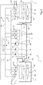
- Each lubrication device 1 represented on the Figures 1 to 4 its function is to lubricate a mechanical system 5 comprising in particular rotating elements, such as shafts and bearings, as well as elements for power transmission and for reducing or increasing rotational speed, such as pinions and / or gears.
- This mechanical system 5 is, for example, a main power gearbox equipping a rotary wing aircraft and comprising three zones 51, 52, 53 which have a significant need for lubrication, as represented in FIGS. Figures 1 to 3 .
- the lubrication device 1 comprises, in common with each example shown on the Figures 1 to 3 , a main reservoir 2 containing a lubricating liquid, two recovery tanks 3,4, a main lubrication circuit 10, a backup lubrication circuit 20, two generators of flow 11, 21 and two 30,40 routing systems respectively attached to a recovery tank 3,4.
- the main lubrication circuit 10 comprises a heat exchanger 12, a filter 13, nozzles 15 and pipes 14 connecting these components of the main lubrication circuit 10.
- the flow generator 11 is called “main flow generator” and allows to draw the lubricating liquid located in the tank 2 via a suction point 19 located in the lower part of the tank 2 and thus supply the main lubrication circuit 10 with the lubricating liquid.
- the lubricating liquid then passes through the heat exchanger 12 in order to be cooled before passing through the filter 13, reaching the nozzles 15 and being sprayed on the zones 51, 52, 53 of the mechanical system 5 to be lubricated. .
- the emergency lubrication circuit 20 comprises, in turn, nozzles 25 and pipes 24.
- the flow generator 21 is called a “backup flow generator” and makes it possible to draw the lubricating liquid situated in the tank 2 via a suction point 29 located in the lower part of the reservoir 2 and thus supply the emergency lubrication circuit 20 with the lubricating liquid.
- the lubricating liquid is thus directed to the nozzles 25 to be sprayed on the areas 51, 52, 53 to be lubricated.
- the nozzles 15, 25 are specific and distinct for the main lubrication circuit 10 and the emergency lubrication circuit 20 as shown in FIGS. Figures 1 to 4 , but can however be confused and common to these two lubrication circuits 10,20.
- the main tank 2 is formed by the central casing of the main power gearbox. Each side casing of this main power gearbox forms a recovery tank 3,4.
- the main tank 2 is thus arranged under the first zone 51 of the main power transmission gearbox while each recovery tank 3,4 is respectively arranged under the second and third zones 52,53 of this main power transmission gearbox.
- the lubricating liquid used to lubricate the first zone 51 flows into the main reservoir 2 and the lubricating liquid used to lubricate the second and third zones 52, 53 flows respectively into a recovery tank 3, 4.
- Each routing system 30,40 is configured to route the lubricating liquid recovered by each recovery tank 3,4 to the main tank 2.
- each conveyance system 30,40 comprises an ejector 35, 45 arranged in a recovery tank 3,4, and first and second lines 32,33,42,43.
- Each ejector 35,45 comprises an inlet nozzle 36,46, a secondary intake channel 37,47 and an outlet 38,48.
- the first pipes 32,42 are connected to the inlet nozzle 36,46 of the ejector 35,45 and the second pipes 33,43 are connected to the outlet 38,48 of the ejector 35,45.
- the ejector 35,45 being arranged in a recovery tank 3,4, the secondary intake channel 37,47 is in contact with the lubricating liquid situated in this recovery tank 3,4, when the ejector 35, 45 is at least partially immersed in this lubricating liquid.
- the first pipes 32,42 of each delivery system 30, 40 connects the ejector 35, 45 simultaneously with the main lubrication circuit 10 and with the back-up lubrication circuit 20.
- each ejector 35, 45 is supplied with lubricating liquid by one either of the main or emergency lubrication circuits 20 or both simultaneously if these two lubrication circuit 10,20 operate simultaneously.
- Each ejector 35,45 is thus fed by the lubricating liquid located in the main tank 2 via the main flow generator 11 and / or the backup flow generator 21.
- the main tank 2 is thus fed with the lubricating liquid recovered in each recovery tank 3,4.
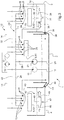
- each of the routing systems 30, 40 of the two examples shown on the figures 2 and 3 is similar to this first example, only the supply means of each ejector 35,45 lubricating liquid being different.
- the lubrication device 1 according to the second example shown in the figure 2 comprises a complementary flow generator 31 sucking the lubricating liquid located in the main reservoir 2.
- the first lines 32,42 then connect each ejector 35,45 to this complementary flow generator 31 to feed this ejector 35,45 with the lubrication fluid located in the main tank 2.
- Each 30,40 routing system thus operates independently of the main lubrication circuit 10 and the backup lubrication circuit 20.
- each routing system 30, 40 has channels 34, 44 connecting each recovery tank 3,4 to the main tank 2.
- These lines 34, 44 are configured so that the lubricating liquid in a recovery tank 3 4 flows by gravity to the main tank 2 when the mechanical system 5 is inclined. Indeed, we can see on the figure 2 that the main tank 2 is arranged above each recovery tank 3,4. As a result, when the mechanical system 5 is not inclined, as shown in FIG. figure 2 , the action of gravity does not allow the routing of the lubricating liquid from each recovery tank 3,4 to the main tank 2 via the pipes 34,44.
- one of the two recovery tanks 3,4 may be above the main tank 2 and thus allow a routing of the lubricating liquid from the recovery tank 3,4 to the main tank 2 via the pipes 34,44.
- This routing may be complementary to the operation of the ejector 35,45 of each routing system 30,40 or to compensate for non-operation of this ejector 35,45 if it had come for example to emerge from the lubricating liquid.
- each routing system 30, 40 includes a non-return device 39, 49, for example a check valve, arranged in each pipe 39, 49 in order to prevent the action of gravity from causing a reverse flow of the main tank. 2 to each recovery tank 3,4.
- a non-return device 39, 49 for example a check valve, arranged in each pipe 39, 49 in order to prevent the action of gravity from causing a reverse flow of the main tank. 2 to each recovery tank 3,4.
- the lubricating device 1 comprises a valve 26 arranged downstream of the emergency flow generator 21 and upstream of the emergency lubrication circuit 20.
- the first lines 32, 42 of each routing system 30, 40 connect each ejector 35 45 In this way, each ejector 35 is supplied with lubricating liquid only by the emergency flow generator 21 supplying the emergency lubrication circuit 20.
- Each conveyor system 30, 40 thus operates independent of the main lubrication circuit 10.
- the valve 26 has at least two positions. In a first position, the valve 26 allows the emergency flow generator 21 to supply with the lubricating liquid located in the main reservoir 2 only the first lines 32, 42 of each conveyor system 30, 40 and consequently each ejector 35,45. In this first position, the emergency lubrication circuit 20 is not supplied with lubricating liquid. This first position of the valve 26 thus allows the delivery by means of each ejector 35,45 of the lubricating liquid located in each recovery tank 3,4 to the main tank 2 without supplying lubricating liquid to the lubrication circuit emergency 20.
- valve 26 In a second position, the valve 26 allows the emergency flow generator 21 to feed simultaneously, with the lubricating liquid located in the main reservoir 2, the first lines 32, 42 of each routing system 30, 40 and the circuit of emergency lubrication 20.
- each routing system 30, 40 has 34,44 lines connecting each recovery tank 3,4 to the main tank 2.
- These pipes 34,44 are configured so that the lubricating liquid located in a recovery tank 3.4 flows by gravity to the main tank 2 when the mechanical system is not or is slightly inclined, the main tank 2 being positioned at a lower level vertically vis-à-vis the recovery tanks 3 , 4 as shown on the figure 3 .
- This routing is then complementary to the operation of the ejector 35,45 of each routing system 30,40.
- the main tank 2 When the mechanical system 5 is inclined, the main tank 2 can be at the same level as above a recovery tank 3,4. In this case, the action of gravity no longer allows the routing of the lubricating liquid from the recovery tank 3,4 to the main tank 2 via the pipes 34,44.
- the ejector 35,45 allows this routing and ensures that the main tank 2 is always supplied by the lubricating liquid located in at least one recovery tank 3,4.
- each routing system 30, 40 includes a check valve 39, 49 arranged in each line 39, 49 to avoid reverse routing of the lubricating liquid in the main tank 2 to each recovery tank.
- the lubrication device 1 can also use a single recovery tank 3 as shown in FIG. figure 4 .
- the mechanical system 5 is for example a main power transmission gear equipping a rotary wing aircraft and having two areas 51,52 to lubricate.
- the main tank 2 is then formed by the central casing of the main power gearbox and the recovery tank 3 is formed by a side casing of this main power gearbox.
- this lubricating device 1 is similar to the first example shown in FIG. figure 1 , the first conduits 32 of the conveyor system 30 connect the ejector 35 simultaneously to the main lubrication circuit 10 and the emergency lubrication circuit 20. In this way, the ejector 35 is supplied with lubricating liquid by one either of the main or emergency lubrication circuits 20 or both at the same time. The ejector 35 is thus fed by the lubricating liquid located in the main tank 2 via the main flow generator 11 and / or the emergency flow generator 21.
- the second conduits 33 connected to the outlet 38 of the ejector 35, allow the lubricating liquid present in the recovery tank 3 to be discharged and then conveyed to the main tank 2.
Landscapes
- Engineering & Computer Science (AREA)
- General Engineering & Computer Science (AREA)
- Mechanical Engineering (AREA)
- Aviation & Aerospace Engineering (AREA)
- General Details Of Gearings (AREA)
- Lubrication Details And Ventilation Of Internal Combustion Engines (AREA)
- Lubrication Of Internal Combustion Engines (AREA)
Priority Applications (1)
| Application Number | Priority Date | Filing Date | Title |
|---|---|---|---|
| PL17186759T PL3301331T3 (pl) | 2016-09-09 | 2017-08-18 | Urządzenie do smarowania, obejmujące wiele zbiorników odzysku na płyn smarny, a także zoptymalizowane, niezawodne środki do jego przekierowywania do zbiornika głównego |
Applications Claiming Priority (1)
| Application Number | Priority Date | Filing Date | Title |
|---|---|---|---|
| FR1601333A FR3055936B1 (fr) | 2016-09-09 | 2016-09-09 | Dispositif de lubrification muni de plusieurs reservoirs de recuperation du liquide de lubrification et de moyens d'acheminement optimises et fiables vers un reservoir principal |
Publications (3)
| Publication Number | Publication Date |
|---|---|
| EP3301331A2 true EP3301331A2 (de) | 2018-04-04 |
| EP3301331A3 EP3301331A3 (de) | 2018-07-25 |
| EP3301331B1 EP3301331B1 (de) | 2020-07-22 |
Family
ID=57749998
Family Applications (1)
| Application Number | Title | Priority Date | Filing Date |
|---|---|---|---|
| EP17186759.1A Active EP3301331B1 (de) | 2016-09-09 | 2017-08-18 | Schmiervorrichtung, die mit mehreren auffangbecken für die schmierflüssigkeit ausgestattet ist, und optimierte und zuverlässige weiterleitungsmittel zum haupttank |
Country Status (4)
| Country | Link |
|---|---|
| EP (1) | EP3301331B1 (de) |
| CA (1) | CA2977151C (de) |
| FR (1) | FR3055936B1 (de) |
| PL (1) | PL3301331T3 (de) |
Families Citing this family (1)
| Publication number | Priority date | Publication date | Assignee | Title |
|---|---|---|---|---|
| DE102018121287A1 (de) * | 2018-08-31 | 2020-03-05 | Claas Material Handling Gmbh | Verladefahrzeugstruktur |
Family Cites Families (7)
| Publication number | Priority date | Publication date | Assignee | Title |
|---|---|---|---|---|
| US4153141A (en) * | 1977-06-20 | 1979-05-08 | General Electric Company | Auxiliary oil supply system |
| DE4227119A1 (de) * | 1992-08-17 | 1994-02-24 | Kloeckner Humboldt Deutz Ag | Ölkreislauf |
| DE10051356B4 (de) * | 2000-10-17 | 2004-05-06 | Daimlerchrysler Ag | Getriebe für eine Hubkolbenbrennkraftmaschine |
| DE10237417A1 (de) * | 2002-08-16 | 2004-02-19 | Daimlerchrysler Ag | Viskohydraulisch geregelte Ölsumpfpumpe |
| US8230835B2 (en) * | 2009-03-10 | 2012-07-31 | Honeywell International Inc. | Emergency engine lubrication systems and methods |
| US20140076661A1 (en) * | 2012-09-19 | 2014-03-20 | United Technologies Corporation | Lubrication system having porous feature |
| FR3027992B1 (fr) * | 2014-10-31 | 2016-12-09 | Airbus Helicopters | Dispositif de lubrification a fiabilite augmentee a triple circuit d'une boite de transmission principale de puissance d'un aeronef |
-
2016
- 2016-09-09 FR FR1601333A patent/FR3055936B1/fr active Active
-
2017
- 2017-08-18 EP EP17186759.1A patent/EP3301331B1/de active Active
- 2017-08-18 PL PL17186759T patent/PL3301331T3/pl unknown
- 2017-08-21 CA CA2977151A patent/CA2977151C/fr active Active
Also Published As
| Publication number | Publication date |
|---|---|
| FR3055936A1 (fr) | 2018-03-16 |
| EP3301331A3 (de) | 2018-07-25 |
| FR3055936B1 (fr) | 2019-06-21 |
| CA2977151C (fr) | 2019-06-11 |
| EP3301331B1 (de) | 2020-07-22 |
| CA2977151A1 (fr) | 2018-03-09 |
| PL3301331T3 (pl) | 2021-01-11 |
Similar Documents
| Publication | Publication Date | Title |
|---|---|---|
| EP2801707B1 (de) | Schmierkreislauf eines Turbotriebwerks mit Überlaufventil für Windmilling | |
| EP3181951B1 (de) | Not-schmiervorrichtung mit vereinfachtem aufbau für ein hauptleistungsübertragungsgetriebe eines luftfahrzeugs | |
| EP3015743B1 (de) | Schmierverfahren und -vorrichtung mit verbesserter zuverlässigkeit mit dreifachkreislauf eines hauptleistungsübertragungsgetriebes eines luftfahrzeugs | |
| EP2834503B1 (de) | Vorrichtung zur rückgewinnung von schmieröl aus einem epizyklischen untersetzungsgetriebe | |
| JP6334534B2 (ja) | ターボ機械用の遊星歯車減速機 | |
| EP3021030B1 (de) | Schmierverfahren und -vorrichtung mit verbesserter zuverlässigkeit mit doppelkreislauf eines hauptleistungsübertragungsgetriebes eines luftfahrzeugs | |
| EP2337931A1 (de) | Verfahren und system zur schmierung eines turbomotors | |
| EP0443901A1 (de) | Hauptgetriebe eines Drehflügelflugzeugs mit einer Notschmiereinrichtung | |
| US10844948B2 (en) | Lubrication device having a plurality of lubrication liquid recovery tanks, and optimized and reliable delivery means to a main tank | |
| JP7222639B2 (ja) | ヘリコプターのトランスミッション潤滑構造 | |
| FR2987402A1 (fr) | Dispositif de lubrification d'un reducteur epicycloidal compatible d'un montage modulaire. | |
| FR3075875B1 (fr) | Circuit d'huile pour turbomachine a boucle d'huile auxiliaire | |
| EP3247924A1 (de) | Integration einer pumpe auf einem ritzelschaft | |
| EP3978784B1 (de) | Schmiersystem mit einem ersatzbehälter | |
| FR3055936B1 (fr) | Dispositif de lubrification muni de plusieurs reservoirs de recuperation du liquide de lubrification et de moyens d'acheminement optimises et fiables vers un reservoir principal | |
| FR2989953A1 (fr) | Reseau d'alimentation en carburant d'un moteur de giravion, comprenant des moyens d'amorcage d'une pompe d'aspiration du carburant depuis une nourrice | |
| DE1653664A1 (de) | Selbstansaugende Zentrifugalpumpe | |
| WO2003074903A2 (fr) | Mécanisme a engrenages a dispositif de contrôle pour la création d'une atmosphère raréfiée | |
| EP4409115B1 (de) | Hilfsöltank für ein flugzeugturbinentriebwerk | |
| EP4127417B1 (de) | Fluggasturbinenaufbau welcher ein verbessertes schmiersystem eines ein gebläse antreibendes untersetzungsgetriebes umfasst | |
| CN109869618B (zh) | 设有多个润滑液回收槽罐以及至主槽罐的优化且可靠的输送装置的润滑装置 | |
| KR102018747B1 (ko) | 윤활액이 담긴 복수의 리커버리 탱크와 메인 탱크로의 최적화되고 믿을 수 있는 전달 수단이 제공된 윤활 장치 | |
| FR3024497B1 (fr) | Ensemble de turbomachine pour l'entrainement d'un fluide d'ecoulement deja utilise vers un element a alimenter | |
| KR102271477B1 (ko) | 유체 이송 디바이스 | |
| WO2026077713A1 (fr) | Désaérateur incurvé installé dans un reservoir d'huile pour turbomachine |
Legal Events
| Date | Code | Title | Description |
|---|---|---|---|
| PUAI | Public reference made under article 153(3) epc to a published international application that has entered the european phase |
Free format text: ORIGINAL CODE: 0009012 |
|
| STAA | Information on the status of an ep patent application or granted ep patent |
Free format text: STATUS: THE APPLICATION HAS BEEN PUBLISHED |
|
| AK | Designated contracting states |
Kind code of ref document: A2 Designated state(s): AL AT BE BG CH CY CZ DE DK EE ES FI FR GB GR HR HU IE IS IT LI LT LU LV MC MK MT NL NO PL PT RO RS SE SI SK SM TR |
|
| AX | Request for extension of the european patent |
Extension state: BA ME |
|
| PUAL | Search report despatched |
Free format text: ORIGINAL CODE: 0009013 |
|
| AK | Designated contracting states |
Kind code of ref document: A3 Designated state(s): AL AT BE BG CH CY CZ DE DK EE ES FI FR GB GR HR HU IE IS IT LI LT LU LV MC MK MT NL NO PL PT RO RS SE SI SK SM TR |
|
| AX | Request for extension of the european patent |
Extension state: BA ME |
|
| RIC1 | Information provided on ipc code assigned before grant |
Ipc: F16H 57/04 20100101AFI20180620BHEP Ipc: B64C 27/12 20060101ALI20180620BHEP |
|
| STAA | Information on the status of an ep patent application or granted ep patent |
Free format text: STATUS: REQUEST FOR EXAMINATION WAS MADE |
|
| 17P | Request for examination filed |
Effective date: 20181008 |
|
| RBV | Designated contracting states (corrected) |
Designated state(s): AL AT BE BG CH CY CZ DE DK EE ES FI FR GB GR HR HU IE IS IT LI LT LU LV MC MK MT NL NO PL PT RO RS SE SI SK SM TR |
|
| STAA | Information on the status of an ep patent application or granted ep patent |
Free format text: STATUS: EXAMINATION IS IN PROGRESS |
|
| 17Q | First examination report despatched |
Effective date: 20190703 |
|
| GRAP | Despatch of communication of intention to grant a patent |
Free format text: ORIGINAL CODE: EPIDOSNIGR1 |
|
| STAA | Information on the status of an ep patent application or granted ep patent |
Free format text: STATUS: GRANT OF PATENT IS INTENDED |
|
| INTG | Intention to grant announced |
Effective date: 20191210 |
|
| RAP1 | Party data changed (applicant data changed or rights of an application transferred) |
Owner name: AIRBUS HELICOPTERS |
|
| GRAJ | Information related to disapproval of communication of intention to grant by the applicant or resumption of examination proceedings by the epo deleted |
Free format text: ORIGINAL CODE: EPIDOSDIGR1 |
|
| STAA | Information on the status of an ep patent application or granted ep patent |
Free format text: STATUS: EXAMINATION IS IN PROGRESS |
|
| INTC | Intention to grant announced (deleted) | ||
| GRAP | Despatch of communication of intention to grant a patent |
Free format text: ORIGINAL CODE: EPIDOSNIGR1 |
|
| STAA | Information on the status of an ep patent application or granted ep patent |
Free format text: STATUS: GRANT OF PATENT IS INTENDED |
|
| INTG | Intention to grant announced |
Effective date: 20200514 |
|
| GRAS | Grant fee paid |
Free format text: ORIGINAL CODE: EPIDOSNIGR3 |
|
| GRAA | (expected) grant |
Free format text: ORIGINAL CODE: 0009210 |
|
| STAA | Information on the status of an ep patent application or granted ep patent |
Free format text: STATUS: THE PATENT HAS BEEN GRANTED |
|
| AK | Designated contracting states |
Kind code of ref document: B1 Designated state(s): AL AT BE BG CH CY CZ DE DK EE ES FI FR GB GR HR HU IE IS IT LI LT LU LV MC MK MT NL NO PL PT RO RS SE SI SK SM TR |
|
| REG | Reference to a national code |
Ref country code: GB Ref legal event code: FG4D Free format text: NOT ENGLISH |
|
| REG | Reference to a national code |
Ref country code: CH Ref legal event code: EP |
|
| REG | Reference to a national code |
Ref country code: DE Ref legal event code: R096 Ref document number: 602017020071 Country of ref document: DE |
|
| REG | Reference to a national code |
Ref country code: AT Ref legal event code: REF Ref document number: 1293691 Country of ref document: AT Kind code of ref document: T Effective date: 20200815 |
|
| REG | Reference to a national code |
Ref country code: IE Ref legal event code: FG4D Free format text: LANGUAGE OF EP DOCUMENT: FRENCH |
|
| REG | Reference to a national code |
Ref country code: LT Ref legal event code: MG4D |
|
| REG | Reference to a national code |
Ref country code: AT Ref legal event code: MK05 Ref document number: 1293691 Country of ref document: AT Kind code of ref document: T Effective date: 20200722 |
|
| PG25 | Lapsed in a contracting state [announced via postgrant information from national office to epo] |
Ref country code: HR Free format text: LAPSE BECAUSE OF FAILURE TO SUBMIT A TRANSLATION OF THE DESCRIPTION OR TO PAY THE FEE WITHIN THE PRESCRIBED TIME-LIMIT Effective date: 20200722 Ref country code: PT Free format text: LAPSE BECAUSE OF FAILURE TO SUBMIT A TRANSLATION OF THE DESCRIPTION OR TO PAY THE FEE WITHIN THE PRESCRIBED TIME-LIMIT Effective date: 20201123 Ref country code: BG Free format text: LAPSE BECAUSE OF FAILURE TO SUBMIT A TRANSLATION OF THE DESCRIPTION OR TO PAY THE FEE WITHIN THE PRESCRIBED TIME-LIMIT Effective date: 20201022 Ref country code: LT Free format text: LAPSE BECAUSE OF FAILURE TO SUBMIT A TRANSLATION OF THE DESCRIPTION OR TO PAY THE FEE WITHIN THE PRESCRIBED TIME-LIMIT Effective date: 20200722 Ref country code: ES Free format text: LAPSE BECAUSE OF FAILURE TO SUBMIT A TRANSLATION OF THE DESCRIPTION OR TO PAY THE FEE WITHIN THE PRESCRIBED TIME-LIMIT Effective date: 20200722 Ref country code: GR Free format text: LAPSE BECAUSE OF FAILURE TO SUBMIT A TRANSLATION OF THE DESCRIPTION OR TO PAY THE FEE WITHIN THE PRESCRIBED TIME-LIMIT Effective date: 20201023 Ref country code: NO Free format text: LAPSE BECAUSE OF FAILURE TO SUBMIT A TRANSLATION OF THE DESCRIPTION OR TO PAY THE FEE WITHIN THE PRESCRIBED TIME-LIMIT Effective date: 20201022 Ref country code: SE Free format text: LAPSE BECAUSE OF FAILURE TO SUBMIT A TRANSLATION OF THE DESCRIPTION OR TO PAY THE FEE WITHIN THE PRESCRIBED TIME-LIMIT Effective date: 20200722 Ref country code: AT Free format text: LAPSE BECAUSE OF FAILURE TO SUBMIT A TRANSLATION OF THE DESCRIPTION OR TO PAY THE FEE WITHIN THE PRESCRIBED TIME-LIMIT Effective date: 20200722 Ref country code: FI Free format text: LAPSE BECAUSE OF FAILURE TO SUBMIT A TRANSLATION OF THE DESCRIPTION OR TO PAY THE FEE WITHIN THE PRESCRIBED TIME-LIMIT Effective date: 20200722 |
|
| PG25 | Lapsed in a contracting state [announced via postgrant information from national office to epo] |
Ref country code: RS Free format text: LAPSE BECAUSE OF FAILURE TO SUBMIT A TRANSLATION OF THE DESCRIPTION OR TO PAY THE FEE WITHIN THE PRESCRIBED TIME-LIMIT Effective date: 20200722 Ref country code: LV Free format text: LAPSE BECAUSE OF FAILURE TO SUBMIT A TRANSLATION OF THE DESCRIPTION OR TO PAY THE FEE WITHIN THE PRESCRIBED TIME-LIMIT Effective date: 20200722 Ref country code: IS Free format text: LAPSE BECAUSE OF FAILURE TO SUBMIT A TRANSLATION OF THE DESCRIPTION OR TO PAY THE FEE WITHIN THE PRESCRIBED TIME-LIMIT Effective date: 20201122 |
|
| REG | Reference to a national code |
Ref country code: DE Ref legal event code: R119 Ref document number: 602017020071 Country of ref document: DE |
|
| PG25 | Lapsed in a contracting state [announced via postgrant information from national office to epo] |
Ref country code: NL Free format text: LAPSE BECAUSE OF FAILURE TO SUBMIT A TRANSLATION OF THE DESCRIPTION OR TO PAY THE FEE WITHIN THE PRESCRIBED TIME-LIMIT Effective date: 20200722 |
|
| REG | Reference to a national code |
Ref country code: CH Ref legal event code: PL |
|
| PG25 | Lapsed in a contracting state [announced via postgrant information from national office to epo] |
Ref country code: DK Free format text: LAPSE BECAUSE OF FAILURE TO SUBMIT A TRANSLATION OF THE DESCRIPTION OR TO PAY THE FEE WITHIN THE PRESCRIBED TIME-LIMIT Effective date: 20200722 Ref country code: CZ Free format text: LAPSE BECAUSE OF FAILURE TO SUBMIT A TRANSLATION OF THE DESCRIPTION OR TO PAY THE FEE WITHIN THE PRESCRIBED TIME-LIMIT Effective date: 20200722 Ref country code: CH Free format text: LAPSE BECAUSE OF NON-PAYMENT OF DUE FEES Effective date: 20200831 Ref country code: RO Free format text: LAPSE BECAUSE OF FAILURE TO SUBMIT A TRANSLATION OF THE DESCRIPTION OR TO PAY THE FEE WITHIN THE PRESCRIBED TIME-LIMIT Effective date: 20200722 Ref country code: LI Free format text: LAPSE BECAUSE OF NON-PAYMENT OF DUE FEES Effective date: 20200831 Ref country code: LU Free format text: LAPSE BECAUSE OF NON-PAYMENT OF DUE FEES Effective date: 20200818 Ref country code: EE Free format text: LAPSE BECAUSE OF FAILURE TO SUBMIT A TRANSLATION OF THE DESCRIPTION OR TO PAY THE FEE WITHIN THE PRESCRIBED TIME-LIMIT Effective date: 20200722 Ref country code: SM Free format text: LAPSE BECAUSE OF FAILURE TO SUBMIT A TRANSLATION OF THE DESCRIPTION OR TO PAY THE FEE WITHIN THE PRESCRIBED TIME-LIMIT Effective date: 20200722 |
|
| REG | Reference to a national code |
Ref country code: BE Ref legal event code: MM Effective date: 20200831 |
|
| PLBE | No opposition filed within time limit |
Free format text: ORIGINAL CODE: 0009261 |
|
| STAA | Information on the status of an ep patent application or granted ep patent |
Free format text: STATUS: NO OPPOSITION FILED WITHIN TIME LIMIT |
|
| PG25 | Lapsed in a contracting state [announced via postgrant information from national office to epo] |
Ref country code: AL Free format text: LAPSE BECAUSE OF FAILURE TO SUBMIT A TRANSLATION OF THE DESCRIPTION OR TO PAY THE FEE WITHIN THE PRESCRIBED TIME-LIMIT Effective date: 20200722 |
|
| 26N | No opposition filed |
Effective date: 20210423 |
|
| PG25 | Lapsed in a contracting state [announced via postgrant information from national office to epo] |
Ref country code: SK Free format text: LAPSE BECAUSE OF FAILURE TO SUBMIT A TRANSLATION OF THE DESCRIPTION OR TO PAY THE FEE WITHIN THE PRESCRIBED TIME-LIMIT Effective date: 20200722 |
|
| PG25 | Lapsed in a contracting state [announced via postgrant information from national office to epo] |
Ref country code: DE Free format text: LAPSE BECAUSE OF NON-PAYMENT OF DUE FEES Effective date: 20210302 |
|
| PG25 | Lapsed in a contracting state [announced via postgrant information from national office to epo] |
Ref country code: BE Free format text: LAPSE BECAUSE OF NON-PAYMENT OF DUE FEES Effective date: 20200831 Ref country code: SI Free format text: LAPSE BECAUSE OF FAILURE TO SUBMIT A TRANSLATION OF THE DESCRIPTION OR TO PAY THE FEE WITHIN THE PRESCRIBED TIME-LIMIT Effective date: 20200722 Ref country code: IE Free format text: LAPSE BECAUSE OF NON-PAYMENT OF DUE FEES Effective date: 20200818 |
|
| REG | Reference to a national code |
Ref country code: NL Ref legal event code: MP Effective date: 20200722 |
|
| GBPC | Gb: european patent ceased through non-payment of renewal fee |
Effective date: 20210818 |
|
| PG25 | Lapsed in a contracting state [announced via postgrant information from national office to epo] |
Ref country code: TR Free format text: LAPSE BECAUSE OF FAILURE TO SUBMIT A TRANSLATION OF THE DESCRIPTION OR TO PAY THE FEE WITHIN THE PRESCRIBED TIME-LIMIT Effective date: 20200722 Ref country code: MT Free format text: LAPSE BECAUSE OF FAILURE TO SUBMIT A TRANSLATION OF THE DESCRIPTION OR TO PAY THE FEE WITHIN THE PRESCRIBED TIME-LIMIT Effective date: 20200722 Ref country code: CY Free format text: LAPSE BECAUSE OF FAILURE TO SUBMIT A TRANSLATION OF THE DESCRIPTION OR TO PAY THE FEE WITHIN THE PRESCRIBED TIME-LIMIT Effective date: 20200722 |
|
| PG25 | Lapsed in a contracting state [announced via postgrant information from national office to epo] |
Ref country code: MK Free format text: LAPSE BECAUSE OF FAILURE TO SUBMIT A TRANSLATION OF THE DESCRIPTION OR TO PAY THE FEE WITHIN THE PRESCRIBED TIME-LIMIT Effective date: 20200722 Ref country code: MC Free format text: LAPSE BECAUSE OF FAILURE TO SUBMIT A TRANSLATION OF THE DESCRIPTION OR TO PAY THE FEE WITHIN THE PRESCRIBED TIME-LIMIT Effective date: 20200722 |
|
| PG25 | Lapsed in a contracting state [announced via postgrant information from national office to epo] |
Ref country code: GB Free format text: LAPSE BECAUSE OF NON-PAYMENT OF DUE FEES Effective date: 20210818 |
|
| P01 | Opt-out of the competence of the unified patent court (upc) registered |
Effective date: 20230530 |
|
| PGFP | Annual fee paid to national office [announced via postgrant information from national office to epo] |
Ref country code: PL Payment date: 20250728 Year of fee payment: 9 Ref country code: IT Payment date: 20250825 Year of fee payment: 9 |
|
| PGFP | Annual fee paid to national office [announced via postgrant information from national office to epo] |
Ref country code: FR Payment date: 20250828 Year of fee payment: 9 |