EP3301332A1 - Ringebalg und verfahren zur herstellung eines ringebalgs - Google Patents
Ringebalg und verfahren zur herstellung eines ringebalgs Download PDFInfo
- Publication number
- EP3301332A1 EP3301332A1 EP17194274.1A EP17194274A EP3301332A1 EP 3301332 A1 EP3301332 A1 EP 3301332A1 EP 17194274 A EP17194274 A EP 17194274A EP 3301332 A1 EP3301332 A1 EP 3301332A1
- Authority
- EP
- European Patent Office
- Prior art keywords
- bellows
- ring
- clamping rings
- clamping
- shell wall
- Prior art date
- Legal status (The legal status is an assumption and is not a legal conclusion. Google has not performed a legal analysis and makes no representation as to the accuracy of the status listed.)
- Withdrawn
Links
- 238000004519 manufacturing process Methods 0.000 title claims abstract description 9
- 239000011324 bead Substances 0.000 claims description 21
- 239000000463 material Substances 0.000 claims description 13
- 239000004033 plastic Substances 0.000 claims description 9
- 229920003023 plastic Polymers 0.000 claims description 9
- 230000005484 gravity Effects 0.000 claims description 3
- 238000000034 method Methods 0.000 claims description 2
- 229920001296 polysiloxane Polymers 0.000 claims description 2
- 238000005086 pumping Methods 0.000 description 5
- 238000013022 venting Methods 0.000 description 5
- 239000007921 spray Substances 0.000 description 4
- 206010040954 Skin wrinkling Diseases 0.000 description 3
- 229920001971 elastomer Polymers 0.000 description 3
- 238000001746 injection moulding Methods 0.000 description 3
- 239000007788 liquid Substances 0.000 description 3
- 125000006850 spacer group Chemical group 0.000 description 3
- VGGSQFUCUMXWEO-UHFFFAOYSA-N Ethene Chemical compound C=C VGGSQFUCUMXWEO-UHFFFAOYSA-N 0.000 description 2
- 229910000831 Steel Inorganic materials 0.000 description 2
- 230000015572 biosynthetic process Effects 0.000 description 2
- 238000010276 construction Methods 0.000 description 2
- 238000013461 design Methods 0.000 description 2
- 229920001684 low density polyethylene Polymers 0.000 description 2
- 239000004702 low-density polyethylene Substances 0.000 description 2
- 239000002184 metal Substances 0.000 description 2
- 229910052751 metal Inorganic materials 0.000 description 2
- 210000002445 nipple Anatomy 0.000 description 2
- 239000010959 steel Substances 0.000 description 2
- 229920002430 Fibre-reinforced plastic Polymers 0.000 description 1
- 208000027418 Wounds and injury Diseases 0.000 description 1
- 230000002745 absorbent Effects 0.000 description 1
- 239000002250 absorbent Substances 0.000 description 1
- 239000000853 adhesive Substances 0.000 description 1
- 230000001070 adhesive effect Effects 0.000 description 1
- 229910052782 aluminium Inorganic materials 0.000 description 1
- XAGFODPZIPBFFR-UHFFFAOYSA-N aluminium Chemical compound [Al] XAGFODPZIPBFFR-UHFFFAOYSA-N 0.000 description 1
- 238000013459 approach Methods 0.000 description 1
- 238000005452 bending Methods 0.000 description 1
- 230000008901 benefit Effects 0.000 description 1
- 230000008859 change Effects 0.000 description 1
- 238000006243 chemical reaction Methods 0.000 description 1
- 230000006835 compression Effects 0.000 description 1
- 238000007906 compression Methods 0.000 description 1
- 238000011109 contamination Methods 0.000 description 1
- 239000002826 coolant Substances 0.000 description 1
- 230000006378 damage Effects 0.000 description 1
- 230000007423 decrease Effects 0.000 description 1
- 230000001419 dependent effect Effects 0.000 description 1
- 238000007598 dipping method Methods 0.000 description 1
- 239000000428 dust Substances 0.000 description 1
- 238000005516 engineering process Methods 0.000 description 1
- 230000002349 favourable effect Effects 0.000 description 1
- 239000011151 fibre-reinforced plastic Substances 0.000 description 1
- 239000011888 foil Substances 0.000 description 1
- 238000002347 injection Methods 0.000 description 1
- 239000007924 injection Substances 0.000 description 1
- 208000014674 injury Diseases 0.000 description 1
- 238000003780 insertion Methods 0.000 description 1
- 230000037431 insertion Effects 0.000 description 1
- 239000010985 leather Substances 0.000 description 1
- 230000005923 long-lasting effect Effects 0.000 description 1
- 230000007246 mechanism Effects 0.000 description 1
- 229920002635 polyurethane Polymers 0.000 description 1
- 239000004814 polyurethane Substances 0.000 description 1
- 238000002360 preparation method Methods 0.000 description 1
- 230000008569 process Effects 0.000 description 1
- 230000002787 reinforcement Effects 0.000 description 1
- 230000003014 reinforcing effect Effects 0.000 description 1
- 229910001220 stainless steel Inorganic materials 0.000 description 1
- 239000010935 stainless steel Substances 0.000 description 1
- 238000004073 vulcanization Methods 0.000 description 1
- 230000037303 wrinkles Effects 0.000 description 1
Images


Classifications
-
- F—MECHANICAL ENGINEERING; LIGHTING; HEATING; WEAPONS; BLASTING
- F16—ENGINEERING ELEMENTS AND UNITS; GENERAL MEASURES FOR PRODUCING AND MAINTAINING EFFECTIVE FUNCTIONING OF MACHINES OR INSTALLATIONS; THERMAL INSULATION IN GENERAL
- F16J—PISTONS; CYLINDERS; SEALINGS
- F16J3/00—Diaphragms; Bellows; Bellows pistons
- F16J3/04—Bellows
- F16J3/041—Non-metallic bellows
-
- A—HUMAN NECESSITIES
- A61—MEDICAL OR VETERINARY SCIENCE; HYGIENE
- A61M—DEVICES FOR INTRODUCING MEDIA INTO, OR ONTO, THE BODY; DEVICES FOR TRANSDUCING BODY MEDIA OR FOR TAKING MEDIA FROM THE BODY; DEVICES FOR PRODUCING OR ENDING SLEEP OR STUPOR
- A61M1/00—Suction or pumping devices for medical purposes; Devices for carrying-off, for treatment of, or for carrying-over, body-liquids; Drainage systems
- A61M1/64—Containers with integrated suction means
- A61M1/68—Containers incorporating a flexible member creating suction
- A61M1/684—Containers incorporating a flexible member creating suction bellows-type
-
- B—PERFORMING OPERATIONS; TRANSPORTING
- B29—WORKING OF PLASTICS; WORKING OF SUBSTANCES IN A PLASTIC STATE IN GENERAL
- B29C—SHAPING OR JOINING OF PLASTICS; SHAPING OF MATERIAL IN A PLASTIC STATE, NOT OTHERWISE PROVIDED FOR; AFTER-TREATMENT OF THE SHAPED PRODUCTS, e.g. REPAIRING
- B29C48/00—Extrusion moulding, i.e. expressing the moulding material through a die or nozzle which imparts the desired form; Apparatus therefor
- B29C48/15—Extrusion moulding, i.e. expressing the moulding material through a die or nozzle which imparts the desired form; Apparatus therefor incorporating preformed parts or layers, e.g. extrusion moulding around inserts
- B29C48/151—Coating hollow articles
- B29C48/152—Coating hollow articles the inner surfaces thereof
-
- F—MECHANICAL ENGINEERING; LIGHTING; HEATING; WEAPONS; BLASTING
- F04—POSITIVE - DISPLACEMENT MACHINES FOR LIQUIDS; PUMPS FOR LIQUIDS OR ELASTIC FLUIDS
- F04B—POSITIVE-DISPLACEMENT MACHINES FOR LIQUIDS; PUMPS
- F04B43/00—Machines, pumps, or pumping installations having flexible working members
- F04B43/08—Machines, pumps, or pumping installations having flexible working members having tubular flexible members
- F04B43/084—Machines, pumps, or pumping installations having flexible working members having tubular flexible members the tubular member being deformed by stretching or distortion
-
- F—MECHANICAL ENGINEERING; LIGHTING; HEATING; WEAPONS; BLASTING
- F04—POSITIVE - DISPLACEMENT MACHINES FOR LIQUIDS; PUMPS FOR LIQUIDS OR ELASTIC FLUIDS
- F04B—POSITIVE-DISPLACEMENT MACHINES FOR LIQUIDS; PUMPS
- F04B45/00—Pumps or pumping installations having flexible working members and specially adapted for elastic fluids
- F04B45/02—Pumps or pumping installations having flexible working members and specially adapted for elastic fluids having bellows
-
- F—MECHANICAL ENGINEERING; LIGHTING; HEATING; WEAPONS; BLASTING
- F16—ENGINEERING ELEMENTS AND UNITS; GENERAL MEASURES FOR PRODUCING AND MAINTAINING EFFECTIVE FUNCTIONING OF MACHINES OR INSTALLATIONS; THERMAL INSULATION IN GENERAL
- F16J—PISTONS; CYLINDERS; SEALINGS
- F16J3/00—Diaphragms; Bellows; Bellows pistons
- F16J3/04—Bellows
- F16J3/048—Bellows with guiding or supporting means
-
- F—MECHANICAL ENGINEERING; LIGHTING; HEATING; WEAPONS; BLASTING
- F16—ENGINEERING ELEMENTS AND UNITS; GENERAL MEASURES FOR PRODUCING AND MAINTAINING EFFECTIVE FUNCTIONING OF MACHINES OR INSTALLATIONS; THERMAL INSULATION IN GENERAL
- F16L—PIPES; JOINTS OR FITTINGS FOR PIPES; SUPPORTS FOR PIPES, CABLES OR PROTECTIVE TUBING; MEANS FOR THERMAL INSULATION IN GENERAL
- F16L11/00—Hoses, i.e. flexible pipes
- F16L11/04—Hoses, i.e. flexible pipes made of rubber or flexible plastics
- F16L11/11—Hoses, i.e. flexible pipes made of rubber or flexible plastics with corrugated wall
- F16L11/115—Hoses, i.e. flexible pipes made of rubber or flexible plastics with corrugated wall having reinforcements not embedded in the wall
-
- B—PERFORMING OPERATIONS; TRANSPORTING
- B29—WORKING OF PLASTICS; WORKING OF SUBSTANCES IN A PLASTIC STATE IN GENERAL
- B29C—SHAPING OR JOINING OF PLASTICS; SHAPING OF MATERIAL IN A PLASTIC STATE, NOT OTHERWISE PROVIDED FOR; AFTER-TREATMENT OF THE SHAPED PRODUCTS, e.g. REPAIRING
- B29C49/00—Blow-moulding, i.e. blowing a preform or parison to a desired shape within a mould; Apparatus therefor
- B29C49/20—Blow-moulding, i.e. blowing a preform or parison to a desired shape within a mould; Apparatus therefor of articles having inserts or reinforcements ; Handling of inserts or reinforcements
- B29C2049/2021—Inserts characterised by the material or type
- B29C2049/2065—Inserts characterised by the material or type for reinforcing specific areas of the final blow moulded article
-
- B—PERFORMING OPERATIONS; TRANSPORTING
- B29—WORKING OF PLASTICS; WORKING OF SUBSTANCES IN A PLASTIC STATE IN GENERAL
- B29C—SHAPING OR JOINING OF PLASTICS; SHAPING OF MATERIAL IN A PLASTIC STATE, NOT OTHERWISE PROVIDED FOR; AFTER-TREATMENT OF THE SHAPED PRODUCTS, e.g. REPAIRING
- B29C2791/00—Shaping characteristics in general
- B29C2791/004—Shaping under special conditions
- B29C2791/006—Using vacuum
-
- B—PERFORMING OPERATIONS; TRANSPORTING
- B29—WORKING OF PLASTICS; WORKING OF SUBSTANCES IN A PLASTIC STATE IN GENERAL
- B29C—SHAPING OR JOINING OF PLASTICS; SHAPING OF MATERIAL IN A PLASTIC STATE, NOT OTHERWISE PROVIDED FOR; AFTER-TREATMENT OF THE SHAPED PRODUCTS, e.g. REPAIRING
- B29C2791/00—Shaping characteristics in general
- B29C2791/004—Shaping under special conditions
- B29C2791/007—Using fluid under pressure
-
- B—PERFORMING OPERATIONS; TRANSPORTING
- B29—WORKING OF PLASTICS; WORKING OF SUBSTANCES IN A PLASTIC STATE IN GENERAL
- B29C—SHAPING OR JOINING OF PLASTICS; SHAPING OF MATERIAL IN A PLASTIC STATE, NOT OTHERWISE PROVIDED FOR; AFTER-TREATMENT OF THE SHAPED PRODUCTS, e.g. REPAIRING
- B29C48/00—Extrusion moulding, i.e. expressing the moulding material through a die or nozzle which imparts the desired form; Apparatus therefor
- B29C48/03—Extrusion moulding, i.e. expressing the moulding material through a die or nozzle which imparts the desired form; Apparatus therefor characterised by the shape of the extruded material at extrusion
- B29C48/09—Articles with cross-sections having partially or fully enclosed cavities, e.g. pipes or channels
- B29C48/10—Articles with cross-sections having partially or fully enclosed cavities, e.g. pipes or channels flexible, e.g. blown foils
-
- B—PERFORMING OPERATIONS; TRANSPORTING
- B29—WORKING OF PLASTICS; WORKING OF SUBSTANCES IN A PLASTIC STATE IN GENERAL
- B29C—SHAPING OR JOINING OF PLASTICS; SHAPING OF MATERIAL IN A PLASTIC STATE, NOT OTHERWISE PROVIDED FOR; AFTER-TREATMENT OF THE SHAPED PRODUCTS, e.g. REPAIRING
- B29C48/00—Extrusion moulding, i.e. expressing the moulding material through a die or nozzle which imparts the desired form; Apparatus therefor
- B29C48/03—Extrusion moulding, i.e. expressing the moulding material through a die or nozzle which imparts the desired form; Apparatus therefor characterised by the shape of the extruded material at extrusion
- B29C48/13—Articles with a cross-section varying in the longitudinal direction, e.g. corrugated pipes
-
- B—PERFORMING OPERATIONS; TRANSPORTING
- B29—WORKING OF PLASTICS; WORKING OF SUBSTANCES IN A PLASTIC STATE IN GENERAL
- B29C—SHAPING OR JOINING OF PLASTICS; SHAPING OF MATERIAL IN A PLASTIC STATE, NOT OTHERWISE PROVIDED FOR; AFTER-TREATMENT OF THE SHAPED PRODUCTS, e.g. REPAIRING
- B29C48/00—Extrusion moulding, i.e. expressing the moulding material through a die or nozzle which imparts the desired form; Apparatus therefor
- B29C48/14—Extrusion moulding, i.e. expressing the moulding material through a die or nozzle which imparts the desired form; Apparatus therefor characterised by the particular extruding conditions, e.g. in a modified atmosphere or by using vibration
- B29C48/147—Extrusion moulding, i.e. expressing the moulding material through a die or nozzle which imparts the desired form; Apparatus therefor characterised by the particular extruding conditions, e.g. in a modified atmosphere or by using vibration after the die nozzle
- B29C48/1472—Extrusion moulding, i.e. expressing the moulding material through a die or nozzle which imparts the desired form; Apparatus therefor characterised by the particular extruding conditions, e.g. in a modified atmosphere or by using vibration after the die nozzle at the die nozzle exit zone
-
- B—PERFORMING OPERATIONS; TRANSPORTING
- B29—WORKING OF PLASTICS; WORKING OF SUBSTANCES IN A PLASTIC STATE IN GENERAL
- B29K—INDEXING SCHEME ASSOCIATED WITH SUBCLASSES B29B, B29C OR B29D, RELATING TO MOULDING MATERIALS OR TO MATERIALS FOR MOULDS, REINFORCEMENTS, FILLERS OR PREFORMED PARTS, e.g. INSERTS
- B29K2083/00—Use of polymers having silicon, with or without sulfur, nitrogen, oxygen, or carbon only, in the main chain, as moulding material
-
- B—PERFORMING OPERATIONS; TRANSPORTING
- B29—WORKING OF PLASTICS; WORKING OF SUBSTANCES IN A PLASTIC STATE IN GENERAL
- B29L—INDEXING SCHEME ASSOCIATED WITH SUBCLASS B29C, RELATING TO PARTICULAR ARTICLES
- B29L2022/00—Hollow articles
- B29L2022/02—Inflatable articles
- B29L2022/025—Bladders
-
- B—PERFORMING OPERATIONS; TRANSPORTING
- B29—WORKING OF PLASTICS; WORKING OF SUBSTANCES IN A PLASTIC STATE IN GENERAL
- B29L—INDEXING SCHEME ASSOCIATED WITH SUBCLASS B29C, RELATING TO PARTICULAR ARTICLES
- B29L2031/00—Other particular articles
- B29L2031/703—Bellows
Definitions
- the invention relates to a bellows and a bladder and / or suction device comprising the bellows, and a method for producing a ring bellows.
- a bellows is a new category of bellows, which can be subsumed under the generic term of the bellows similar to the category of disc bellows.
- a bellows is an "accordion" collapsible hose made of a plastic or leather material that is attached over mechanically interlocking or rotating lubricated machine parts to protect it from external influences, particularly dirt and seal against the environment, or as an extendable loading tube or used as bladder and / or Saugbalg.
- the bellows component in a device for compressing gaseous media, for pumping liquid media or for sucking liquid or gaseous media.
- a bladder and / or suction bellows consists of a deformable hollow body, which is usually equipped with at least one valve. By the first valve, the gaseous medium is sucked in expansion of the bellows, when the bellows is operated as a suction bellows; in the other direction, ie when compressing the bellows locks the first valve.
- the first valve When the bellows is operated as a bellows, the first valve is designed so that upon compression of the bellows, the gaseous medium is blown out of the bellows through the first valve and upon expansion of the bellows, the valve blocks, so that the gaseous medium is not in the reverse direction can penetrate into the bellows.
- Early forms of bladder and / or suction bellows were entirely devoid of valves, and the operator had to put his hand in front of the mouth. It is also possible that the bellows does not perform a recurring stretching or Georgiazeihen, but only an expansion (suck) or a contracting movement (blow out) and then emptied or refilled. In this way, the annular bellows according to the invention can be operated as a bladder and / or Saugbalg.
- An example of a pump operable with a bellows is a diaphragm pump.
- Disc bellows are made of flat discs glued at the inner circumference to the inner circumference of the next disc and at the outer circumference to the outer circumference of the next disc. For this purpose, individual discs are punched out, stacked and vulcanized on the inner and outer sides. As a result, a small Caribbean Sears is achieved. Rubber disc bellows are ground before delivery. Depending on the length and application, plain bushings, support disks or wire rings are used to stabilize the disc bellows.
- Multiflex bellows are made of thermosplastic plastic. Multiflex bellows are so-called dipping parts, for the production of which a mold is required. To stabilize the wrinkles can be stiffened with wire rings.
- bellows are often made by injection molding. Typical materials are TPE, polyurethane or soft PVC. Whether vulcanized bellows, rubber disc bellows, sturdy bellows or slide guards, the selection of different materials and designs is great.
- a bellows which serves to protect a joint of a propeller shaft.
- the bellows consists of a shell with longitudinally spaced outwardly projecting outer folds.
- the outer folds are connected by means of inverted, elastic shell parts, which are pulled out at kink movements of the propeller shaft on the outer side and the inner side are compressed.
- Such a bellows construction serves to repel dirt; it is not suitable for axial pumping actions.
- the prior art bellows are not stretchable relative to the circumference of the fold edges, both the inner fold edge and the outer fold edge, and the circumference of the fold edges remains the same, regardless of whether the bellows folds "accordion-like” or unfolds "accordion-like” or this is kinked with respect to the central axis.
- the inner folds of conventional bellows counteract the unfolding, because they represent a material reinforcement as kink edges and the bending edge always strives to the rest position, i. in the direction of an angle of 0 °. Under its own weight, conventional bellows do not fold evenly, but more strongly at the top, where more gravity acts and less at the bottom.
- bellows are often made of a rubber material that exhibits a long-lasting odor. This odor is not usable in medical technology and especially in rooms in which people are staying permanently, such. Patients in a treatment room or hospital room. It is therefore necessary to make bellows made of a more compatible material, e.g. does not emit an unpleasant odor.
- the bellows can be compressed for venting of articles of daily use with a gaseous working medium, preferably air, for venting from an extended working position during a pumping operation or be pulled out for venting from a compressed working position during a suction.
- a gaseous working medium preferably air
- the evacuation volume is approximately equal to the volume created by evacuation of the annular bellows, preferably evacuation by application of gravity to the lower bellows end using a valve defining the passage of the inflowing medium.
- the starting point for the bellows is an elastic bellows cover that is elastic in the circumference and, according to one embodiment, is substantially cylindrical in shape, apart from the fold edges.
- the bellows sheath may e.g. consist of an endless tube.
- Conventional bellows or molded bellows have a rigid bellows sheath that moves only along the fold edges and where the sheath wall is not stretched elastically and therefore strives inward with a force.
- clamping rings are placed for the preparation of the annular bellows along the bellows cover at a distance of the bellows folds to be formed and their formation in radial planes, which form the Balgfalten of the annular bellows by stretching the shell wall.
- the clamping rings are inserted into the bellows cover or placed on it and thereby brought into the desired positions.
- the clamping rings stretch the bellows cover in the area of the bellows folds and form the outer fold edge.
- the initially non-functional bellows cover is converted into a bellows with a few conversions.
- the bellows is preferably operated suspended vertically.
- the bellows portions between the bellows folds have, where they are not stretched by clamping rings, an inwardly constricted course, which changes in the pumping operations between constricted and collapsed shape and extended shape in which the constrictions smooth and expand in the direction of the circumference of the clamping rings.
- the bellows has a good dimensional stability. In addition there is a good circumferential extensibility of the zones between the bellows folds.
- the inwardly constricted course represents the inner fold edge, without this actually has to form or form an edge, but rather a round arc, for example in parabolic shape, is formed.
- the good elastic circumferential extensibility is crucial while additional extensibility in length, ie not obligatory in the direction of the axis of the hoop, is only an option.
- the elastic bellows cover is provided in the radial planes of the folds to be formed axially with spaced pairs of ridges or rows of grooves or a groove which protrude in the pairs towards each other from the shell wall and run all around.
- the clamping rings are engaged behind by the beads or rows of nubs inside and are fixed by clamping between the beads or rows of nubs and shell heads that surround the clamping rings outside and the extension and stretching of the shell wall to form the Bellows folds have arisen.
- clamping rings always have a larger circumference than the unstretched bellows casing, preferably an at least 5% larger circumference, preferably at least 10%, in particular at least 20% larger circumference.
- the bellows has at least three clamping rings, preferably at least 6.
- the clamping rings according to the requirements are circular or deviating from the circular shape, for example, oval shaped.
- the circular cylindrical shape is the simplest; However, external constraints may require different shapes, for example.
- the clamping rings are either made of wire, such as stainless V2A steel, or made of plastic, such as fiber-reinforced plastic. For subsequent insertion into the inner circumference, it may be desirable to fold the ring into an eight and unfold the ring at its destination. Possibly. Slices are also possible.
- the clamping rings vary alternately in the circumference, so that in each case a larger follows a smaller clamping ring on or in the bellows. This has the advantage that, when the annular bellows are compressed, the smaller clamping ring is accommodated in the circumference of the larger one and so bellows height can be saved.
- each of the smaller clamping rings in turn can accommodate an adjacent ring in its scope until finally followed by a larger clamping ring, which is similar to the former larger clamping ring and which in turn follow three cascading smaller smaller clamping rings, etc.
- the clamping rings are provided exclusively to stretch the bellows cover in the scope and not or not additionally provided to narrow the scope of the bellows cover. Constraints of the bellows cover as inner bellows folds are preferably formed exclusively by the elastic restoring force of the shell wall.
- an inner clamping ring may also be set up an outer ring or preferably several ring sections from the outside on the inner clamping ring to clamp the inner clamping ring, the outer ring or ring section engages over the shell wall and engages around the inner clamping ring.
- the outer ring or the ring sections may be made of plastic or metal.
- the bellows cover is formed of an elastic tear-resistant and substantially gas-tight material. Suitable materials include silicone plastics. An example of this is vinylmethylpolysiloxane or LDPE, for example with a thickness of 25 ⁇ m (mu).
- the bellows sheath preferably has a material thickness of e.g. about 0.01 to 2 mm, in particular 0.05 to 1 mm and particularly preferably from 0.2 to 0.8 mm.
- the bellows of the present invention is simpler and lighter than other bellows.
- the forming of the ring bellows with clamping rings brings a significant material and cost savings, especially against disc bellows.
- the bellows in the shell wall surface is about 40% smaller, which is explained by the fact that it can constructively have fewer bellows folds. As a result, the height can be lower.
- the elasticity of the annular bellows is greater than the disc bellows produced by vulcanization.
- the bellows is suitable for example as a suction device for ventilating absorbent articles such as diapers, diaper pants or bandages, as shown in the WO 2014180461 A1 is described.
- the bellows extends in the vertical direction against a spring tension, which corresponds to the elongation of the inner shell in the region of the constrictions.
- the constrictions that form the inner (round) folds expand until they resemble the circumference of the outer folds in the area of the clamping rings.
- the bellows with inserted clamping rings can be made, for example, by hanging the bellows cover in a cylindrical shape and clamped at the top with an expander.
- the bellows is also clamped at the bottom with an expander and the bellows cover is applied by pressure plan to the cylinder inner wall.
- an automatic sprayer is integrated, which is horizontally and vertically movable and is aligned with the height of the clamping ring.
- the fixation of the clamping rings on the bellows is as follows. The spacer with the spray nozzle moves from the automatic spray gun to the clamping ring.
- the machine injects from the inside via the clamping ring a thin liquid reactive plastic, which connects the ring and the bellows on both sides.
- the spacer pulls back and the shaft then moves the injection molding machine a clamping ring deeper. Thereafter, the next working part repeats until the last clamping ring. Finally, both expander are loosened and removed, and the bellows removed from the cylinder shape.
- Fig. 1 shows a bellows cover 1, which is used to form a cylindrical annular bellows 2 according to the invention.
- the bellows cover 1 is clamped vertically suspended;
- the shell wall 3 of the bellows cover 1 is flexible, well stretchable and tear-resistant in the extent used.
- connecting rings 5 are provided for connection to a pump mechanism, not shown.
- the connecting rings 5 are made of a rigid material, such as metal, preferably stainless steel.
- the connecting rings 5 comprise the shell wall 3 at the bellows 4 and set them at the upper or lower circular periphery of the lid, not shown.
- the bellows cover 1 six circular clamping rings 10 are used.
- Fig. 2 shows a circular clamping ring 10, which in the bellows cover 1 after FIG. 1 is used.
- the diameter of the clamping ring 10 or its circumference is so large that the clamping ring clearly expands the bellows casing 1 in the region of the bellows folds 8.
- the clamping rings form the bellows folds 8 of the ring bellows 2 Fig.1 ,
- Figure 3 shows the bellows cover 1 which has become a bellows 2.
- Circular clamping rings 10 are inserted into the bellows cover 1. Their radial extent is so great that they clearly expand the bellows envelope 1 in the region of the bellows folds 8. Thus they form the outer bellows folds 8 of the ring bellows second
- the diameter x in the region of the inner bellows folds 11 increases in the direction of the value y.
- the outer circumference of the annular bellows approaches a cylindrical shape.
- the lower bellows end 4 is in Fig. 3 and Fig. 5 in diameter compared to the initial diameter x slightly reduced.
- Fig. 4 shows a section of the bellows cover 1 in the region of the bellows folds 8.
- the beads 7 are provided in pairs. The pairs have distances to adjacent bead pairs which determine the distances between the bellows folds 8 of the ring bellows 2 to be formed.
- the beads 7 run around the bellows cover 1. In a variant, it is intended to interrupt them, so that 7 rows of nubs arise from the beads.
- Figure 4 shows on the basis of an enlarged section through the folded bellows 2 after Fig. 3 the structural design of the bellows folds 8.
- the bellows cover 1 With the clamping ring 10, the bellows cover 1 is stretched and extended in the region of the bellows folds 8.
- the extended parts 12 in the region of the inner bellows folds 11 of the bellows cover 1 are located laterally on the clamping ring 10.
- the round in cross-section clamping ring 10 is engaged behind by the beads 7 of the bellows cover. 1
- the clamping ring 10 is thus clamped inside between the beads 7, which form a groove in between. It is possible to change the construction in that the clamping rings 1 are placed on the bellows cover 1 from the outside. In this case, the beads 7 are molded on the outside (not shown).
- Fig. 5 shows the bellows 2 after Fig. 3 in vertical hanging condition without clamping rings.
- the bellows parts 12 between the bellows folds 8 have due to the lack of clamping rings 10 is still no constricted inside course.
- the bellows cover has a substantially cylindrical shape.
- All clamping rings 10 of a ring bellows 2 are equally shaped. But they can also be different from model to model. Thus, the clamping rings 10 may also be oval or elliptical. Only clamping rings 10 with angular shapes are i.d.R. less preferred.
- Fig. 6 is an aspirator comprising a bellows in suspended, weighted form, shown to produce a desired negative pressure in its interior deployment.
- the bellows vacuum cleaner 13 is fully extended in the illustration. He has 3 or more clamping rings 10th
- a price particularly favorable embodiment which can also be used as a disposable disposable article, consists of a stretchable film tube eg LDPE 25 microns.
- the clamping rings 10 can be inserted rings made of plastic or steel, or they are produced by injection molding.
- the function of the bellows-suction device 13 is as follows: The sucker is hung with the handle 14 to a tripod and the bellows cover 1 is plugged into a hose connection 20. Thereafter, a weight 15 is stapled under the bottom 16 to generate the negative pressure. With the factory set via a throttle valve suction amount of about 200 ml / min, the function begins.
- the hose from the hose connector 20 and the weight 15 are removed from the bottom 16.
- the disposable nipple is carried with the handle 4 perpendicular to disposal and emptied by pulling the volume opening 18. Then the bellows-suction cup 13 decreases again.
- Fig. 7 the bellows vacuum cleaner 13 is folded in the commercial form shown with bottom 16 and cover 17 made of aluminum foil.
- a hose connection 20 with an opening in the bellows and a still closed film opening 18, which is required for disposal of the bellows-suction.
- a handle 14 is attached, which also serves to hang on a tripod.
- a Velcro 19 is attached to which the weight stops.
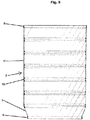
- Fig. 8 shows the bellows-sucker from above. He is intended as a once-to-use merchandise.
- a set consisting of tripod and weight, for example, about 250 grams, with the opposite side of the Velcro tape are offered separately for permanent reuse.
- a stretchable in length bellows cover 1 for example, from a film tube with a thickness of 0.02 - 1.0 mm, is hung in a cylinder 21 with a larger circumference and airtight clamped at the top with an expander 22 and expansion rings 27.
- a sprayer 24 is integrated, which is horizontally and / or vertically movable and can be moved by a shaft 29 in height.
- Below (not shown) is used as above, tightening the bellows cover 1, a second expander.
- the second expander has a pressure equalization valve. Pressure is built up inside the bellows cover 1 via this valve. The air between outer surface of the bellows cover 1 and cylinder 21, displaced downwards ( Fig. 9 ) and can escape through the residual gap 23.
- the production of the clamping rings 10 on the inside of the bellows cover 1 is as follows:
- the height-controlled injection machine 24 is moved with the shaft 29 to the height.
- the shaft 29 runs in a shaft sleeve 28.
- the distance part 25 with the spray nozzle 26 moves controlled at a distance in front of the inner wall of the bellows cover 1.
- the sprayer 24 carries at one or more 360 ° horizontal turns a curing, on the surface of the adhesive plastic ring.
- Fig. 10 shows the production of the clamping ring of the second level from above.
- the clamping ring 10 of the first level is completed.
- Fig. 11 the two expander 22 are removed and the pressure is balanced.
- the deformation of the bellows casing between the clamping rings 10, is restored to the original dimension (inner bellows folds 11).
- the curing of the material of the injected rings leads to a minimal shrinkage, thereby the finished bellows can be easily removed from the cylinder.
Landscapes
- Engineering & Computer Science (AREA)
- General Engineering & Computer Science (AREA)
- Mechanical Engineering (AREA)
- Health & Medical Sciences (AREA)
- Heart & Thoracic Surgery (AREA)
- Vascular Medicine (AREA)
- Anesthesiology (AREA)
- Biomedical Technology (AREA)
- Hematology (AREA)
- Life Sciences & Earth Sciences (AREA)
- Animal Behavior & Ethology (AREA)
- General Health & Medical Sciences (AREA)
- Public Health (AREA)
- Veterinary Medicine (AREA)
- Diaphragms And Bellows (AREA)
Abstract
Die Erfindung bezieht sich auf einen Ringebalg umfassend eine Balghülle (1) mit einer elastischen Hüllenwand (3), an der in Radialebene steife Spannringe (10) festgesetzt werden, die durch Dehnen der Hüllenwand (3) Balgfalten (8) bilden und eine Blase- und/oder Saugvorrichtung umfassend den Ringebalg, sowie ein Verfahren zur Herstellung des Ringebalgs
Description
- Die Erfindung bezieht sich auf einen Ringebalg und eine Blase- und/oder Saugvorrichtung umfassend den Ringebalg, sowie ein Verfahren zur Herstellung eines Ringebalgs. Ein Ringebalg ist eine neue Kategorie von Faltenbalg, der ähnlich wie die Kategorie der Scheibenbälge unter den Oberbegriff der Faltenbälge subsummiert werden kann.
- Ein Faltenbalg ist ein "ziehharmonikaartig" zusammenfaltbarer Schlauch aus einem Kunststoff- oder Ledermaterial, der zum Schutz über sich mechanisch ineinanderschiebende oder drehende, geschmierte Maschinenteile angebracht wird, um sie vor Fremdeinflüssen, insbesondere Verschmutzung zu schützen und gegenüber der Umgebung abzudichten, oder als ausziehbarer Verladeschlauch oder als Blase- und/oder Saugbalg eingesetzt wird.
- Wird der Faltenbalg als Blase- und/oder Saugbalg betrieben, ist der Faltenbalg Bauteil in einer Vorrichtung zum Verdichten von gasförmigen Medien, zum Pumpen von flüssigen Medien oder zum Ansaugen von flüssigen oder gasförmigen Medien. Ein Blase- und/oder Saugbalg besteht aus einem verformbaren hohlen Körper, der i.d.R. mit zumindest einem Ventil ausgestattet ist. Durch das erste Ventil wird das gasförmige Medium beim Ausdehnen des Faltenbalgs eingesaugt, wenn der Faltenbalg als Saugbalg betrieben wird; in der anderen Richtung, d.h. beim Zusammendrücken des Faltenbalgs, sperrt das erste Ventil. Wird der Faltenbalg als Blasebalg betrieben, ist das erste Ventil so gestaltet, dass beim Zusammendrücken des Faltenbalgs das gasförmige Medium aus dem Faltenbalg durch das erste Ventil herausgeblasen wird und beim Ausdehnen des Faltenbalgs, das Ventil sperrt, so dass das gasförmige Medium nicht in umgekehrter Richtung in den Faltenbalg eindringen kann. Frühe Formen des Blase- und/oder Saugbalgs waren gänzlich ohne Ventile ausgebildet, und der Betreiber musste seine Hand vor die Öffnung setzen. Auch ist es möglich, dass der Faltenbalg kein wiederkehrendes Dehnen oder Zusammenzeihen ausführt, sondern lediglich eine Dehn- (ansaugen) oder eine Zusammenziehbewegung (herausblasen) und danach entleert bzw. wieder befüllt wird. In dieser Weise kann auch der erfindungsgemäße Ringebalg als Blase- und/oder Saugbalg betrieben werden. Ein Beispiel für eine mit einem Faltenbalg betreibbare Pumpe ist eine Membranpumpe.
- Scheibenbälge werden aus flachen Scheiben hergestellt, die jeweils am inneren Umfang mit dem inneren Umfang der nächsten Scheibe und am äußeren Umfang mit dem äußeren Umfang der nächsten Scheibe verklebt sind. Hierzu werden einzelne Scheiben ausgestanzt, aufeinandergelegt und an den Innen- und Außenseiten vulkanisiert. Dadurch wird ein kleines Zusammendruckmaß erreicht. Gummischeibenbälge werden vor Auslieferung geschliffen. Je nach Länge und Anwendung werden zur Stabilisierung der Scheibenbälge Gleitbuchsen, Stützscheiben oder Drahtringe verwendet.
- Multiflex-Bälge (auch Theku-Bälge genannt) sind aus thermosplastischem Kunststoff. Multiflex-Bälge sind sog. Tauchteile, für deren Herstellung eine Form erforderlich ist. Zur Stabilisierung können die Falten mit Drahtringen versteift werden.
- Heute werden Faltenbälge häufig durch Spritzgießen hergestellt. Typische Materialien sind TPE, Polyurethan oder weich-PVC. Ob vulkanisierte Bälge, Gummischeibenbälge, robuste Bälge oder Gleitbahnschützer, die Auswahl an unterschiedlichsten Materialien und Ausführungsformen ist groß.
- In der
DE 102004037715 A1 ist ein Faltenbalg beschrieben, der dem Schutz eines Gelenkes einer Gelenkwelle dient. Der Faltenbalg besteht aus einer Hülle mit in Längsrichtung mit Abstand voneinander nach außen vorstehenden Außenfalten. Die Außenfalten sind mittels eingestülpter, elastischer Hüllenteile verbunden, die bei Knickbewegungen der Gelenkwelle auf der außen gelegenen Seite ausgezogen und der innen liegenden Seite zusammengedrückt werden. Eine solche Balgkonstruktion dient dem Schmutzabweisen; sie eignet sich nicht für axiale Pumpaktionen. - Aus der
DE 202013008103 U1 ist ein Faltenbalg mit einer Mehrzahl von zueinander beweglichen Stützrahmen bekannt, wobei jeweils zwei benachbarte Stützrahmen über einen flexiblen Balgabschnitt mit Falte miteinander verbunden sind. Derartige Gleitbahnschützer werden an Maschinen zum Schutz gegen Verschmutzung der Gleitbahnen durch Staub, Späne, Kühlmittel usw. eingesetzt. Dem Menschen dienen sie zudem als Schutz vor Verletzungen beim Arbeiten an der Maschine (z. B. als Eingriffsschutz, Quetschschutz). Für Gleitbahnschützer sind etwaige innere Stütz- und Verstärkungsrahmen mit der Balgdecke thermisch verschweißt. - Die Faltenbälge nach dem Stand der Technik sind bezogen auf den Umfang der Faltkanten, sowohl der inneren Faltenkante als auch der äußeren Faltenkante, nicht dehnbar und der Umfang der Faltkanten bleibt immer gleich, egal ob sich der Faltenbalg "ziehharmonikaartig" zusammenfaltet oder "ziehharmonikaartig" auseinanderfaltet oder dieser in Bezug auf die Mittelachse geknickt wird. Die inneren Faltkanten herkömmlicher Faltenbälge wirken dem Auseinanderfalten entgegen, weil sie als Knickkanten eine Materialverstärkung darstellen und die Knickkante immer in die Ruhelage strebt, d.h. in Richtung eines Winkels von 0°. Unter dem Eigengewicht falten sich herkömmliche Faltenbälge nicht gleichmäßig auf, sondern oben stärker, wo mehr Schwerkraft wirkt und unten weniger.
- Es ist Aufgabe der Erfindung, eine neue Kategorie von Faltenbalg für eine Vorrichtung zum Be- und Entlüften mit einem gasförmigen Medium zu schaffen, der bei einem einfachen Aufbau eingebaut zum Belüften axial zusammendrückbar und zum Entlüften des Gebrauchsartikels auseinanderziehbar ist. Es soll also ein Faltenbalg für eine Pump- und Absaugfunktion sein, insbesondere eine Absaugfunktion.
- Weiterhin sind herkömmliche Faltenbälge häufig aus einem Gummimaterial, das langanhaltend einen starken Geruch entfaltet. Dieser Geruch ist in der Medizintechnik und insbesondere in Räumen in denen sich Personen auf Dauer aufhalten nicht einsetzbar, wie z.B. Patienten in einem Behandlungsraum oder Krankenzimmer. Es gilt daher Bälge zugänglich zu machen, die aus einem besser verträglichem Material bestehen, dass z.B. keinen unangenehmen Geruch absondert.
- Die gestellte Aufgabe ist erfindungsgemäß durch den Gegenstand der unabhängigen Patentansprüche gelöst. Vorteilhafte Ausgestaltungen sind Gegenstand der Unteransprüche oder nachfolgend beschrieben.
- Der Ringebalg kann zum Be- und Entlüften von Gebrauchsartikeln mit einem gasförmigen Arbeitsmedium, vorzugsweise Luft, zum Belüften aus einer ausgezogenen Arbeitsstellung während eines Pumpvorganges zusammengedrückt werden oder zum Entlüften aus einer zusammengedrückten Arbeitsstellung während eines Absaugvorganges ausgezogen werden.
- In einer bevorzugten Ausführungsform entspricht das Absaugvolumen etwa dem Volumen, das durch Ausziehen des Ringebalgs entsteht, vorzugsweise Ausziehen durch Anwendung der Schwerkraft auf das untere Balgende unter Verwendung eines den Durchlass des einströmenden Mediums begrenzenden Ventils.
- Ausgangsbasis für den Ringebalg ist eine im Umfang elastische Balghülle, die nach einer Ausgestaltung ausgedehnt im Wesentlichen zylinderförmig ist, abgesehen von den Faltenkanten. Die Balghülle kann z.B. aus einem Endlosschlauch bestehen. Herkömmliche Faltenbalge oder gespritzte Balge weisen eine starre Balghülle auf, die sich nur entlang der Faltkanten bewegt und wo die Hüllenwand nicht elastisch gedehnt ist und daher mit einer Kraft nach innen strebt.
- An der Hüllenwand der Balghülle sind zur Herstellung des Ringebalgs längs der Balghülle im Abstand der zu bildenden Balgfalten und zu deren Ausbildung in Radialebenen steife Spannringe platziert, die durch Dehnen der Hüllenwand die Balgfalten des Ringebalgs bilden. Bei der Montage werden die Spannringe in die Balghülle eingeführt oder auf diese aufgesetzt und dabei in die gewünschten Positionen gebracht. Die Spannringe dehnen die Balghülle im Bereich der Balgfalten und bilden die äußere Faltenkante aus. Damit ist die zunächst funktionslose Balghülle mit wenigen Umbauten in einen Ringebalg umgewandelt.
- Der Ringebalg wird vorzugsweise vertikal eingehängt betrieben. Die Balghüllenteile zwischen den Balgfalten haben dort, wo sie nicht durch Spannringe gedehnt sind, einen nach innen eingeschnürten Verlauf, der sich bei den Pumpvorgängen ändert und zwar zwischen eingeschnürter und zusammengefalteter Gestalt und ausgedehnter Gestalt, in der sich die Einschnürungen glätten und ausdehnen in Richtung auf den Umfang der Spannringe. Der Ringebalg hat eine gute Formstabilität. Dazu kommt eine gute Umfangsdehnbarkeit der Zonen zwischen den Balgfalten.
- Der nach innen eingeschnürte Verlauf stellt die innere Faltenkante dar, ohne dass diese tatsächlich eine Kante ausbildet bzw. ausbilden muss, vielmehr wird vorzugsweise ein runder Bogen, z.B. in Parabelform, ausgebildet. Die gute elastische Umfangsdehnbarkeit ist entscheidend während eine zusätzliche Dehnbarkeit in der Länge, d.h. in Richtung der Achse des Ringebalgs nicht obligatorisch ist und nur eine Option ist.
- Nach einer weiteren Ausgestaltung der Erfindung ist vorgesehen, dass die elastische Balghülle in den Radialebenen der auszubildenden Falten axial mit auf Abstand paarweise angeordneten Wülsten oder Noppenreihen oder einer Nut versehen ist, die bei den Paaren aufeinander zu aus der Hüllenwand hervorstehen und rundum laufen.
- Nach einer weiteren Ausgestaltung der Erfindung ist vorgesehen, dass die Spannringe von den Wülsten oder Noppenreihen innen hintergriffen werden und damit durch Einklemmen fixiert sind zwischen den Wülsten oder Noppenreihen und Hüllenköpfen, die die Spannringe außen umgreifen und die beim Ausziehen und Dehnen der Hüllenwand zur Bildung der Balgfalten entstanden sind.
- Es ist vorgesehen, dass die Spannringe stets einen größeren Umfang als die ungedehnte Balghülle haben, vorzugsweise einen zumindest 5 % größeren Umfang, vorzugsweise einen zumindest 10%, insbesondere mindestens 20% größeren Umfang.
- Nach einer weiteren Ausgestaltung der Erfindung ist vorgesehen, dass die Wülste oder Noppenreihen aus der Hüllenwand nach außen hervorstehen für außen auf die Balghülle aufgesetzte Spannringe, die von den Wülsten oder Noppenreihen außen übergriffen und damit die Spannringe durch Einklemmen fixiert werden zwischen den Wülsten oder Noppenreihen und den die Spannringe innen umgreifenden Hüllenwandköpfen.
- Es ist vorgesehen, dass der Ringebalg mindestens drei Spannringe aufweist, vorzugsweise mindestens 6.
- Nach einer weiteren Ausgestaltung der Erfindung ist vorgesehen, dass die Spannringe den Anforderungen entsprechend kreisrund oder von der Kreisform abweichend, beispielsweise oval geformt sind. Die kreisrunde Zylinderform ist die einfachste; äußere Zwänge können aber beispielsweise abweichende Formen nötig machen.
- Die Spannringe sind entweder aus Draht gefertigt, etwa rostfreiem V2A-Stahl, oder aus Kunststoff, etwa faserverstärkten Kunststoff. Zum nachträglichen einsetzen in den Innenumfang kann es erwünscht sein den Ring zu einer Acht zu falten und den Ring an seinem Bestimmungsort zu entfalten. Ggf. sind auch Scheiben möglich.
- Nach einer weiteren Ausgestaltung der Erfindung ist vorgesehen, dass die Spannringe alternierend im Umfang variieren, so dass jeweils ein größerer einem kleineren Spannring auf oder in dem Balg folgt. Dies hat den Vorteil, dass beim Zusammendrücken des Ringebalgs der kleinere Spannring in dem Umfang des größeren aufgenommen wird und sich so Balghöhe einsparen lässt.
- Denkbar sind auch andere ähnliche Anordnungen, wo zum Beispiel zunächst auf einen größeren Spannring drei kleinere Spannringe folgen, wobei jeder der kleineren Spannringe seinerseits einen benachbarten Ring in seinem Umfang aufnehmen kann, bis schließlich wieder ein größerer Spannring folgt, der dem erstgenannten größeren Spannring gleicht und dem wiederum drei kaskadenartig kleiner werdende kleinere Spannringe folgen usw.
- Nach einer bevorzugten Ausführungsform sind die Spannringe ausschließlich dazu vorgesehen, die Balghülle im Umfang zu strecken und nicht bzw. nicht zusätzlich dazu vorgesehen, den Umfang der Balghülle einzuengen. Einengungen der Balghülle wie innere Balgfalten bilden sich vorzugsweise ausschließlich durch die elastische Rückstellkraft der Hüllenwand aus.
- Auch ist es möglich neben einem inneren Spannring weiterhin jeweils einen äußeren Ring oder bevorzugt mehrere Ringabschnitte von außen auf den inneren Spannring aufzusetzen, um den inneren Spannring klammerartig festzusetzen, wobei der äußere Ring oder Ringabschnitt über die Hüllenwand greift und den inneren Spannring umgreift. Der äußere Ring oder die Ringabschnitte können aus Kunststoff oder Metall sein.
- Die Balghülle ist aus einem elastischen reißfesten und im Wesentlichen gasdichten Material gebildet. Geeignete Materialien sind etwa Silicon-Kunststoffe. Ein Beispiel hierfür ist Vinlymethylpolysiloxan oder LDPE, z.B. mit einer Dicke von 25 µm (mü).
- Die Balghülle hat vorzugsweise eine Materialstärke von z.B. ca. 0,01 bis 2 mm, insbesondere 0,05 bis 1 mm und besonders bevorzugt von 0,2 bis 0,8 mm.
- Der Ringebalg nach der vorliegenden Erfindung ist einfacher und leichter als andere Faltenbälge. Das Formen des Ringebalgs mit Spannringen bringt eine deutliche Material- und Kostenersparnis, insbesondere gegenüber Scheibenbälgen. Im Vergleich zu herkömmlichen gespritzten Faltenbälgen und Scheibenbälgen ist bei gleichem Volumen, der Ringebalg in der Hüllenwandfläche ca. 40% kleiner, was sich damit erklärt, dass er konstruktiv weniger Balgfalten haben kann. Dadurch kann die Bauhöhe geringer sein. Die Elastizität des Ringebalgs ist größer als die durch Vulkanisieren hergestellter Scheibenbälge.
- Der Ringebalg ist beispielsweise als Absaugvorrichtung geeignet für zu belüftende Absorptionsartikel wie Windeln, Windelhosen oder Binden, wie dies in der
WO 2014180461 A1 beschrieben ist. Eine Vorrichtung in der der Ringebalg einsetzbar ist, ist z.B. in derDE 102014101922 B3 beschrieben. - Interessant ist auch, dass sich der Ringebalg in vertikaler Richtung gegen eine Federspannung auszieht, die der Dehnung der Innenhülle im Bereich der Einschnürungen entspricht. Die Einschnürungen, die die inneren (runden) Falten bilden, dehnen sich aus, bis sie dem Umfang der äußeren Falten im Bereich der Spannringe ähneln.
- Der Ringebalg mit eingesetzten Spannringen kann z.B. hergestellt werden, indem die Balghülle in eine Zylinderform gehängt und oben mit einem Expander eingespannt wird. Der Balg wird unten ebenfalls mit einem Expander eingespannt und die Balghülle durch Druck plan an die Zylinderinnenwand angelegt. Im oberen Expander ist ein Spritzautomat integriert, der horizontal und vertikal beweglich ist und auf die Höhe des Spannringes ausgerichtet wird. Die Fixierung der Spannringe auf den Balg erfolgt wie folgt. Das Distanzteil mit der Spritzdüse fährt aus dem Spritzautomaten bis an den Spannring. Bei einer 380° Horizontaldrehung, spritzt der Automat von innen über den Spannring einen dünnflüssigen reaktiven Kunststoff, der den Ring und den Balg beidseitig verbindet. Nach Beendigung des ersten Arbeitsteils, zieht sich das Distanzteil wieder zurück und die Welle fährt danach den Spritzautomaten einen Spannring tiefer. Danach widerholt sich der nächste Arbeitsteil, bis zum letzten Spannring. Zum Abschluss werden beide Expander gelöst und entfernt, und der Ringebalg aus der Zylinderform entnommen.
- Die Erfindung wird anhand der Zeichnung näher erläutert, ohne auf diese beschränkt zu sein. Es zeigen:
-
Fig.1 eine Balghülle, die durch Ansetzen von Spannringen im Bereich der zu bildenden Falten des Balgs zu einem Ringebalg geworden ist, -
Fig. 2 einen Spannring, wie er in die Balghülle nach Figur eingesetzt ist, -
Fig. 3 den vor einem Auseinanderfalten zusammengelegten und gefalteten Ringebalg mit von innen eingesetzten Spannringen, die die Balghülle im Bereich der Falten ausdehnen und damit die Balgfalten bilden, -
Fig. 4 eine vergrößerte Darstellung der Ausbildung einer Balgfalte des Ringebalgs nachFig. 3 mit einem an der Balghülle vorgesehenem Paar von Wülsten, die in Längsrichtung der zu bildenden Balgfalte in Radialebenen an der Hüllenwand umlaufen, wobei auf die Hüllenwand nachFig. 3 in der Nut, die sich zwischen den Wülsten verläuft, jeweils Spannringe aufgesetzt sind, die die Hüllenwand zum Bilden der Balgfalten ausziehen und dehnen und wobei die Wülste die hintergriffenen Spannringe in den Radialebenen der Balgfalten fixieren, -
Fig. 5 den Ringebalg noch ohne Spannringe im hängend gestreckten Zustand, wobei die Ringbalghülle drucklos vertikal am oberen Anschlussring hängt. Der untere Teil mit Anschlussring ist im Querschnitt reduziert, -
Fig. 6 bis 8 einen Ringebalg-Sauger mit dem erfindungsgemäßen Ringebalg, und -
Fig. 9 bis 11 ein Verfahren zur Herstellung eine Ringebalgs. -
Fig. 1 zeigt eine Balghülle 1, die zur Bildung eines zylindrischen Ringebalgs 2 nach der Erfindung benutzt wird. Die Balghülle 1 ist vertikal hängend eingespannt; Die Hüllenwand 3 der Balghülle 1 ist flexibel, gut dehnbar und im verwendeten Umfang reißfest. An den oberen und unteren Balgenden 4 sind Anschlussringe 5 zum Anschluss an einen nicht dargestellten Pumpmechanismus vorgesehen. Die Anschlussringe 5 bestehen aus einem steifen Material, wie beispielsweise Metall, vorzugsweise korrosionsfreiem Stahl. - Die Anschlussringe 5 umfassen die Hüllenwand 3 an den Balgenden 4 und legen diese am oberen bzw. unteren kreisrunden Umfang des nicht dargestellten Deckels fest. In die Balghülle 1 sind sechs kreisrunde Spannringe 10 eingesetzt.
-
Fig. 2 zeigt einen kreisrunde Spannring 10, der in die Balghülle 1 nachFigur 1 eingesetzt ist. Der Durchmesser des Spannrings 10 bzw. sein Umfang ist so groß, dass der Spannring die Balghülle 1 im Bereich der Balgfalten 8 deutlich ausdehnt. Damit bilden die Spannringe die Balgfalten 8 des Ringebalgs 2 nachFig.1 . -
Fig.3 zeigt die zu einem Ringebalg 2 gewordene Balghülle 1. In die Balghülle 1 sind kreisrunde Spannringe 10 eingesetzt. Ihre radiale Ausdehnung ist so groß, dass sie die Balghülle 1 im Bereich der Balgfalten 8 deutlich ausdehnen. Damit bilden sie die äußeren Balgfalten 8 des Ringebalgs 2. - Durch das Auffalten der Falten 8 vergrößert sich der Durchmesser x im Bereich der inneren Balgfalten 11 in Richtung auf den Wert y. Der Außenumfang des Ringebalgs nähert sich einer zylindrischen Form. Das untere Balgende 4 ist in
Fig. 3 undFig. 5 im Durchmesser gegenüber dem Ausgangsdurchmesser x etwas verkleinert. -
Fig. 4 zeigt einen Ausschnitt aus der Balghülle 1 im Bereich der Balgfalten 8. Man sieht inFig. 4 in Radialebene 6 innen an die Hüllenwand 3 der Balghülle 1 angespritzte Erhebungen, die Wülste 7 bilden. Die Wülste 7 sind paarweise vorgesehen. Die Paare haben zu benachbarten Wulstpaaren Abstände, die die Abstände der zu bildenden Balgfalten 8 des Ringebalgs 2 bestimmen. Die Wülste 7 laufen rund um die Balghülle 1. In einer Variante ist vorgesehen, sie zu unterbrechen, sodass aus den Wülsten 7 Noppenreihen entstehen.Fig.4 zeigt anhand eines vergrößerten Ausschnittes durch den zusammengefalteten Ringebalg 2 nachFig. 3 den konstruktiven Aufbau der Balgfalten 8. - Mit dem Spannring 10 ist die Balghülle 1 im Bereich der Balgfalten 8 gedehnt und ausgezogen. Die ausgezogenen Teile 12 im Bereich der inneren Balgfalten 11 der Balghülle 1 liegen seitlich am Spannring 10 an. Der im Querschnitt runde Spannring 10 wird hintergriffen von den Wülsten 7 der Balghülle 1.
- Der Spannring 10 ist also innen eingeklemmt zwischen den Wülsten 7, die dazwischenliegend eine Nut ausbilden. Es ist möglich, die Konstruktion dadurch zu verändern, dass die Spannringe 1 von außen auf die Balghülle 1 aufgesetzt werden. In diesem Fall sind auch die Wülste 7 außen angespritzt (nicht dargestellt).
-
Fig. 5 zeigt den Ringebalg 2 nachFig. 3 in vertikal hängendem Zustand ohne Spannringe. Die Balghüllenteile 12 zwischen den Balgfalten 8 haben aufgrund der fehlenden Spannringe 10 noch keinen nach innen eingeschnürten Verlauf. Die Balghülle hat im Wesentlichen eine zylindrische Form. - Alle Spannringe 10 eines Ringebalgs 2 sind gleichgeformt. Von Modell zu Modell können sie aber auch verschieden sein. So können die Spannringe 10 auch oval oder elliptisch sein. Nur Spannringe 10 mit eckigen Formgebungen sind i.d.R. weniger bevorzugt.
- In
Fig. 6 ist ein Absauger umfassend einen Ringebalg in hängender, mit einem Gewicht belasteter Form, gezeigt, um bei seiner Entfaltung im inneren einen gewollten Unterdruck zu erzeugen. Der Ringebalg-Sauger 13 ist in der Darstellung voll ausgestreckt. Er besitzt 3 oder mehr Spannringe 10. - Eine preislich besonders günstige Ausführungsform, die auch als Einweg-Wegwerfartikel eingesetzt werde kann, besteht aus einem dehnbarem Folienschlauch z.B. LDPE 25 µm. Die Spannringe 10 können eingesetzte Ringe aus Kunststoff oder Stahl sein, oder sie werden im Spritzverfahren hergestellt. Die Funktion des Ringebalg-Saugers 13 ist wie folgt: Der Sauger wird mit dem Griff 14 an ein Stativ gehängt und die Balghülle 1 an einen Schlauchanschluss 20 gesteckt. Danach wird zur Erzeugung des Unterdrucks ein Gewicht 15 unter den Boden 16 geheftet. Mit der werksseitig über ein Drosselventil eingestellten Absaugmenge von ca. 200 ml / min beginnt die Funktion. Wenn der Absaugprozess beendet ist, bzw. der Sauger voll ausgesteckt ist, werden der Schlauch vom Schlauchanschluss 20 und das Gewicht 15 vom Boden 16 abgezogen. Der Einmal-Sauger wird mit dem Griff 4 senkrecht zur Entsorgung getragen und durch Aufziehen der Volumenöffnung 18 entleert. Dann verkleinert sich der Ringebalg-Sauger 13 wieder.
- In
Fig. 7 ist der Ringebalg-Sauger 13 in der Handelsform zusammengefaltet gezeigt mit Boden 16 und Deckel 17 aus Alu-Folie. In einer Vertiefung des Deckels ist ein Schlauchanschluss 20 mit Öffnung in den Balg und eine noch verschlossene Folienöffnung 18, die zur Entsorgung des Ringebalg-Saugers benötigt wird. Zur Handhabung ist ein Griff 14 angebracht, der auch zum Aufhängen an ein Stativ dient. In der Vertiefung des Bodens ist eine Seite eines Klettbandes 19 angebracht, an dem das Gewicht halt findet. -
Fig. 8 zeigt den Ringebalg-Sauger von oben. Er ist als einmal zu verwendende Handelsware gedacht. Zu ihrem Gebrauch, werden separat zur ständigen Wiederverwendung, ein Set bestehend aus Stativ und Gewicht, z.B. ca. 250 Gramm, mit Gegenseite des Klettbandes angeboten. - Nachfolgend wird ein Verfahren zur Herstellung des Ringebalges 2 erläutert. Eine in der Länge dehnbare Balghülle 1, z.B. aus einem Folienschlauch mit einer Stärke von 0,02 - 1,0 mm, wird in einen Zylinder 21 mit größerem Umfang gehängt und oben mit einem Expander 22 und Dehnungsringen 27 luftdicht eingespannt. Im oberen Expander 22 ist ein Spritzautomat 24 integriert, der horizontal und/oder vertikal beweglich ist und über eine Welle 29 in der Höhe verfahrbar ist. Unten (nicht gezeigt) wird wie oben, bei Straffung der Balghülle 1 ein zweiter Expander eingesetzt. Der zweite Expander hat ein Ventil für den Druckausgleich. Über dieses Ventil wird Druck im Inneren der Balghülle 1 aufgebaut. Dabei wird die Luft zwischen Außenfläche der Balghülle 1 und Zylinder 21, nach unten verdrängt (
Fig. 9 ) und kann durch den Restspalt 23 entweichen. - Danach liegt der Balghülle 1 geweitet an der Innenwand des Zylinders 21 (
Fig. 10 ) und der zweite Expander wurde ebenfalls luftdicht gegen die Form gepresst. Die Herstellung der Spannringe 10 auf der Innenseite der Balghülle 1 erfolgt wie folgt: Der auf Höhe gesteuerte Spritzautomat 24 wird mit der Welle 29 auf die Höhe gefahren. Die Welle 29 läuft in einer Wellenmanschette 28. Das Distanz-Teil 25 mit der Spritzdüse 26 fährt gesteuert auf Abstand vor die Innenwand der Balghülle 1. In einer oder mehreren Lagen, trägt der Spritzautomat 24 bei einer oder mehreren 360° Horizontaldrehungen einen aushärtenden, auf dem Untergrund haftenden Ring aus Kunststoff auf.Fig. 10 zeigt die Herstellung des Spannringes der zweiten Ebene von oben. Der Spannring 10 der ersten Ebene ist fertig gestellt. - In
Fig. 11 sind die zwei Expander 22 entfernt und der Druck ist ausgeglichen. Die Verformung der Balghülle zwischen den Spannringen 10, ist auf das ursprüngliche Maß zurückgestellt (innere Balgfalten 11). Die Aushärtung des Materials der gespritzten Ringe führt zu einer minimalen Schrumpfung, dadurch lässt sich der fertige Balg einfach aus dem Zylinder entnehmen.Bezugszeichenliste: (1) Balghülle (16) Boden (2) Ringebalg (17) Deckel (3) Hüllenwand (18) Volumenöffnung (4) Oberes und unteres Ende der Balghülle (19) Klettband (5) Anschlussringe (20) Schlauchanschluss (6) Radialebenen der Balgfalten (21) Zylinder (7) Erhebungen in Form von Wülsten (22) Expander (8) Balgfalten (23) Restspalt (9) Nut (24) Spritzautomat (10) Spannringe (25) Distanzteil (11) innere Balgfalte (26) Spritzdüse (12) Balghüllenteile zwischen Balgfalten (27) Dehnungsring (13) Ringebalg-Sauger (28) Wellenmanschette (14) Griff (29) Welle (15) Gewicht
Claims (15)
- Ringebalg (2) umfassend eine Balghülle (1), die aufweist eine elastische schlauchförmige Hüllenwand (3), an der in Radialebene zumindest drei steife Spannringe (10) festgesetzt sind, die durch Dehnen der Hüllenwand (3) im Umfang herausstehende Balgfalten (8) bilden, wobei die Spannringe (10) einen größeren Durchmesser als die ungedehnte elastische Hüllenwand (3) haben und die Hüllenwand (3) zwischen den Balgfalten (8) zumindest im zusammengefalteten Zustand elastisch zurückspringt.
- Ringebalg nach Anspruch 1, wobei zum Bestimmen der Sitzposition der Spannringe (10) an der Hüllenwand (3) in den Radialebenen (6) der zu bildenden Balgfalten (8) Erhebungen (7) oder Vertiefungen an der Hüllenwand (3) vorgesehen sind, die die Spannringe (10) verrutschsicher festlegen.
- Ringebalg nach Anspruch 2, wobei die Hüllenwand (3) jeweils in den Radialebenen (6) der auszubildenden Balgfalten (8) aufweist:- auf Abstand angeordnete und umlaufende Wülste (7) oder Noppenreihen, die als Erhebungen jeweils beidseitig der Spannringe (10) aus der Hüllenwand (3) hervorstehen, oder- eine umlaufende Nut (9), die jeweils einen Spannring in der Nut (9) aufnimmt.
- Ringebalg nach Anspruch 2, wobei die Wülste (7) oder Noppenreihen oder die Nut aus der Hüllenwand (3) nach innen hervorstehen für innen auf der Hüllenwand (3) aufgesetzte Spannringe (10).
- Ringebalg nach Anspruch 2 oder 3, wobei die Wülste (7) oder Noppenreihen oder die Nut aus der Hüllenwand (3) nach außen hervorstehen für außen auf der Hüllenwand (3) aufgesetzte Spannringe (10), die von den Wülsten (7) oder Noppenreihen oder der Nut außen übergriffen werden und damit durch Einklemmen fixiert sind und die Spannringe vorzugsweise ein- bzw. aufgeklebt sind.
- Ringebalg nach Anspruch 1 oder 2, wobei die Spannringe (10) innen und/oder außen auf der Hüllenwand (3) aufgeklebt sind, aufgespritzt sind oder thermisch aufgesiegelt sind oder ein innerer Spannring jeweils von einem einen äußeren Ring oder mehreren Ringabschnitte, die außen aufgesetzt werden klammerartig festgesetzt wird, wobei der äußere Ring oder Ringabschnitt über die Hüllenwand greift.
- Ringebalg nach einem der vorhergehenden Ansprüche, wobei der Ringebalg (2) mit mindestens sechs von Spannringen (10) gebildeten Balgfalten (8) versehen ist.
- Ringebalg nach einem der vorhergehenden Ansprüche, wobei die Spannringe (10) kreisrund oder oval geformt sind.
- Ringebalg nach einem der vorhergehenden Ansprüche, wobei die Spannringe zumindest teilweise alternierend im Umfang variieren, insbesondere so dass ein größerer einem kleineren Spannring auf oder in dem Balg folgt.
- Ringebalg nach einem der vorhergehenden Ansprüche, wobei die Hüllenwand aus einem elastischen Schlauch, vorzugsweise aus einem Silicon-Kunststoff, gebildet ist mit einer Materialstärke von 0,01 bis 2 mm.
- Blase- und/oder Saugvorrichtung umfassend den Ringebalg nach zumindest einem der vorhergehenden Ansprüche und weiterhin zumindest ein Ventil.
- Saugvorrichtung nach Anspruch 11, wobei das Ventil ein Nadelventil ist und der Ringebalg als Saugbalg ausgebildet ist.
- Saugvorrichtung nach Anspruch 11 oder 12, wobei der Ringebalg ein Saugbalg ist und ein gasförimiges Medium ansaugt durch Auseinanderfalten des Ringebalges nur unter Schwerkraftwirkung und im Wesentlichen in Lotrichtung.
- Verfahren zur Herstellung eines Ringebalgs nach einem der Ansprüche 1 bis 10 bzw. der Saugvorrichtung nach Anspruch 11 bis 13, wobei die Spannringe (10) auf die ausgedehnte Innenseite der Balghülle (1) aufgespritzt werden und sich unter Aushärten ausbilden.
- Verfahren nach Anspruch 14, wobei die Balghülle (1) gegen die Innenwände eines runden oder ovalen Zylinders (21) durch einen Innendruck gepresst wird, bevor die Spannringe (10) auf die gestreckte Innenseite der Balghülle (1) aufgespritzt werden.
Applications Claiming Priority (1)
| Application Number | Priority Date | Filing Date | Title |
|---|---|---|---|
| DE102016118636.8A DE102016118636B3 (de) | 2016-09-30 | 2016-09-30 | Ringebalg und Blase- und/oder Saugvorrichtung umfassend den Ringebalg |
Publications (1)
| Publication Number | Publication Date |
|---|---|
| EP3301332A1 true EP3301332A1 (de) | 2018-04-04 |
Family
ID=60009492
Family Applications (1)
| Application Number | Title | Priority Date | Filing Date |
|---|---|---|---|
| EP17194274.1A Withdrawn EP3301332A1 (de) | 2016-09-30 | 2017-09-30 | Ringebalg und verfahren zur herstellung eines ringebalgs |
Country Status (2)
| Country | Link |
|---|---|
| EP (1) | EP3301332A1 (de) |
| DE (1) | DE102016118636B3 (de) |
Cited By (4)
| Publication number | Priority date | Publication date | Assignee | Title |
|---|---|---|---|---|
| WO2019028244A1 (en) * | 2017-08-02 | 2019-02-07 | Sharkninja Operating Llc | FLEXIBLE PIPE WITH COMPACT STORAGE CONFIGURATION AND CLEANING APPARATUS USING SUCH A FLEXIBLE PIPE |
| CN112318844A (zh) * | 2020-09-25 | 2021-02-05 | 湖南协成管业科技有限公司 | 一种骨架增强内肋缠绕结构壁管道及其加工方法 |
| CN115300706A (zh) * | 2022-10-12 | 2022-11-08 | 山东第一医科大学附属省立医院(山东省立医院) | 一种神经外科临床用积液冲洗装置 |
| CN117233359A (zh) * | 2023-11-15 | 2023-12-15 | 孚迪斯石油化工科技(葫芦岛)股份有限公司 | 一种航空润滑油轴承试验装置 |
Families Citing this family (2)
| Publication number | Priority date | Publication date | Assignee | Title |
|---|---|---|---|---|
| CN109215406A (zh) * | 2018-11-05 | 2019-01-15 | 淄博职业学院 | 一种智能调节式中文教学显示装置 |
| FR3092736B1 (fr) * | 2019-02-14 | 2021-10-22 | Philippe Mulot | pompe grand volume pour le gonflage d'éléments gonflables |
Citations (6)
| Publication number | Priority date | Publication date | Assignee | Title |
|---|---|---|---|---|
| US2397257A (en) * | 1943-02-04 | 1946-03-26 | Philip P Goland | Surgical suction apparatus |
| US2446281A (en) * | 1944-05-11 | 1948-08-03 | Us Rubber Co | Corrugated tube manufacture |
| DE1257087B (de) * | 1959-08-18 | 1967-12-28 | Teddington Bellows Ltd | Verfahren zum Herstellen biegsamer Metallbaelge |
| DE102005023723B3 (de) * | 2005-05-24 | 2006-12-07 | Meurer, Jan | Faltenschlauch aus verformbarem Material |
| US20110016657A1 (en) * | 2009-07-23 | 2011-01-27 | Dyson Technology Limited | Surface cleaning appliance |
| DE202013100893U1 (de) * | 2013-03-01 | 2014-06-04 | Möllerflex GmbH | Flexibler Schlauch |
Family Cites Families (6)
| Publication number | Priority date | Publication date | Assignee | Title |
|---|---|---|---|---|
| DE2255070A1 (de) * | 1972-11-10 | 1974-05-30 | Kurt Hennig | Faltenbalg |
| AU511049B2 (en) * | 1975-07-16 | 1980-07-24 | Theuniversity Of Melbourne | Diaphragm operated suction pump |
| DE102004037715A1 (de) * | 2004-08-04 | 2006-02-23 | Gkn Driveline International Gmbh | Faltenbalg mit integriertem Falten-Gelenkbereich |
| DE102013104659A1 (de) * | 2013-05-06 | 2014-11-06 | Eberhard Timm GmbH | Entlüftungsvorrichtung für oder als Bestandteil eines Absorptionsartikels |
| DE202013008103U1 (de) * | 2013-09-13 | 2013-10-22 | Arno Arnold Gmbh | Faltenbalg mit versteiftem Stützrahmen |
| DE102014101922B3 (de) * | 2014-02-14 | 2015-07-30 | Eberhard Timm GmbH | Gerät zum Absaugen von gasförmigen oder flüssigen Medien |
-
2016
- 2016-09-30 DE DE102016118636.8A patent/DE102016118636B3/de not_active Expired - Fee Related
-
2017
- 2017-09-30 EP EP17194274.1A patent/EP3301332A1/de not_active Withdrawn
Patent Citations (6)
| Publication number | Priority date | Publication date | Assignee | Title |
|---|---|---|---|---|
| US2397257A (en) * | 1943-02-04 | 1946-03-26 | Philip P Goland | Surgical suction apparatus |
| US2446281A (en) * | 1944-05-11 | 1948-08-03 | Us Rubber Co | Corrugated tube manufacture |
| DE1257087B (de) * | 1959-08-18 | 1967-12-28 | Teddington Bellows Ltd | Verfahren zum Herstellen biegsamer Metallbaelge |
| DE102005023723B3 (de) * | 2005-05-24 | 2006-12-07 | Meurer, Jan | Faltenschlauch aus verformbarem Material |
| US20110016657A1 (en) * | 2009-07-23 | 2011-01-27 | Dyson Technology Limited | Surface cleaning appliance |
| DE202013100893U1 (de) * | 2013-03-01 | 2014-06-04 | Möllerflex GmbH | Flexibler Schlauch |
Cited By (7)
| Publication number | Priority date | Publication date | Assignee | Title |
|---|---|---|---|---|
| WO2019028244A1 (en) * | 2017-08-02 | 2019-02-07 | Sharkninja Operating Llc | FLEXIBLE PIPE WITH COMPACT STORAGE CONFIGURATION AND CLEANING APPARATUS USING SUCH A FLEXIBLE PIPE |
| US10986970B2 (en) | 2017-08-02 | 2021-04-27 | Sharkninja Operating Llc | Flexible hose with compact storage configuration and a cleaning apparatus using the same |
| US11839347B2 (en) | 2017-08-02 | 2023-12-12 | Sharkninja Operating Llc | Flexible hose with compact storage configuration and a cleaning apparatus using the same |
| CN112318844A (zh) * | 2020-09-25 | 2021-02-05 | 湖南协成管业科技有限公司 | 一种骨架增强内肋缠绕结构壁管道及其加工方法 |
| CN115300706A (zh) * | 2022-10-12 | 2022-11-08 | 山东第一医科大学附属省立医院(山东省立医院) | 一种神经外科临床用积液冲洗装置 |
| CN117233359A (zh) * | 2023-11-15 | 2023-12-15 | 孚迪斯石油化工科技(葫芦岛)股份有限公司 | 一种航空润滑油轴承试验装置 |
| CN117233359B (zh) * | 2023-11-15 | 2024-02-02 | 孚迪斯石油化工科技(葫芦岛)股份有限公司 | 一种航空润滑油轴承试验装置 |
Also Published As
| Publication number | Publication date |
|---|---|
| DE102016118636B3 (de) | 2018-01-25 |
Similar Documents
| Publication | Publication Date | Title |
|---|---|---|
| EP3301332A1 (de) | Ringebalg und verfahren zur herstellung eines ringebalgs | |
| DE3126949A1 (de) | Absaugvorrichtung fuer geschlossene wunden | |
| DE2540138C3 (de) | Ringförmige Stützeinlage für einen Prothesenschaft | |
| DE3241845C2 (de) | Ernährungssauger | |
| DE3784095T2 (de) | Absauger. | |
| DE60018950T2 (de) | Gegen zusammendrücken beständige wellschlauchverbindung | |
| EP2075025B1 (de) | Atemmaske mit einer Auslasseinrichtung | |
| DE60024901T2 (de) | Verfahren zur Herstellung eines aus Fasern bestehenden Formteils | |
| DE60212659T2 (de) | Staubsauger und schlauch hierfür | |
| EP4104876A1 (de) | Brusthaube mit flexiblem rand | |
| DE112011105852T5 (de) | Schutzabdeckung und Verfahren zu deren Herstellung | |
| DE10018870C2 (de) | Zitzengummi | |
| EP3614977B1 (de) | Linersystem und verfahren zum anlegen eines linersystems | |
| WO2018130248A1 (de) | Saugpumpe und unterdruck-haltevorrichtung mit saugpumpe und verfahren zum anbringen einer unterdruck-haltevorrichtung | |
| EP1750563B1 (de) | Gerätegehäuse für einen bodenstaubsauger | |
| EP0713691A2 (de) | Lagerungshilfe zur Lagerung von Patientenkörperteilen | |
| DE202015106699U1 (de) | Luftventil für eine aufblasbare Luftmatratze oder Luftmatte | |
| DE4112211A1 (de) | Biegsamer schlauch | |
| DE202013100893U1 (de) | Flexibler Schlauch | |
| EP3893815B1 (de) | Orthopädietechnische einrichtung | |
| EP2126369B1 (de) | Strukturbauteil | |
| EP3535004B1 (de) | Trachealkanüle mit einer abdichteinrichtung | |
| EP4183304B1 (de) | Absaugschnittstelle zur luftdichten verbindung eines ersten strömungskanals mit einem zweiten strömungskanal, basisstation mit einer absaugschnittstelle und system aus einem saugreinigungsgerät und einer basisstation | |
| DE4208266C2 (de) | Membran mit einem Boden, insbesondere für einen Stellantrieb | |
| DE69203857T2 (de) | Melkmaschinenschlauch. |
Legal Events
| Date | Code | Title | Description |
|---|---|---|---|
| PUAI | Public reference made under article 153(3) epc to a published international application that has entered the european phase |
Free format text: ORIGINAL CODE: 0009012 |
|
| STAA | Information on the status of an ep patent application or granted ep patent |
Free format text: STATUS: THE APPLICATION HAS BEEN PUBLISHED |
|
| AK | Designated contracting states |
Kind code of ref document: A1 Designated state(s): AL AT BE BG CH CY CZ DE DK EE ES FI FR GB GR HR HU IE IS IT LI LT LU LV MC MK MT NL NO PL PT RO RS SE SI SK SM TR |
|
| AX | Request for extension of the european patent |
Extension state: BA ME |
|
| STAA | Information on the status of an ep patent application or granted ep patent |
Free format text: STATUS: THE APPLICATION IS DEEMED TO BE WITHDRAWN |
|
| 18D | Application deemed to be withdrawn |
Effective date: 20181005 |