EP3301382A1 - Ölabscheider/-kollektor - Google Patents
Ölabscheider/-kollektor Download PDFInfo
- Publication number
- EP3301382A1 EP3301382A1 EP16824206.3A EP16824206A EP3301382A1 EP 3301382 A1 EP3301382 A1 EP 3301382A1 EP 16824206 A EP16824206 A EP 16824206A EP 3301382 A1 EP3301382 A1 EP 3301382A1
- Authority
- EP
- European Patent Office
- Prior art keywords
- oil
- container body
- chamber
- gas outlet
- compressed gas
- Prior art date
- Legal status (The legal status is an assumption and is not a legal conclusion. Google has not performed a legal analysis and makes no representation as to the accuracy of the status listed.)
- Withdrawn
Links
- 238000005192 partition Methods 0.000 claims abstract description 69
- 238000011144 upstream manufacturing Methods 0.000 claims description 8
- 239000003921 oil Substances 0.000 description 334
- 238000000926 separation method Methods 0.000 description 12
- 230000000694 effects Effects 0.000 description 10
- 239000010687 lubricating oil Substances 0.000 description 8
- 238000011156 evaluation Methods 0.000 description 6
- 238000004519 manufacturing process Methods 0.000 description 5
- 238000001816 cooling Methods 0.000 description 2
- 238000010586 diagram Methods 0.000 description 2
- 238000009434 installation Methods 0.000 description 2
- 239000007788 liquid Substances 0.000 description 2
- 230000000717 retained effect Effects 0.000 description 2
- 238000007789 sealing Methods 0.000 description 2
- 230000007423 decrease Effects 0.000 description 1
- 238000011143 downstream manufacturing Methods 0.000 description 1
- 238000013213 extrapolation Methods 0.000 description 1
- 230000001050 lubricating effect Effects 0.000 description 1
- 230000014759 maintenance of location Effects 0.000 description 1
- 239000002184 metal Substances 0.000 description 1
- 238000000034 method Methods 0.000 description 1
- 238000004088 simulation Methods 0.000 description 1
Images


Classifications
-
- F—MECHANICAL ENGINEERING; LIGHTING; HEATING; WEAPONS; BLASTING
- F04—POSITIVE - DISPLACEMENT MACHINES FOR LIQUIDS; PUMPS FOR LIQUIDS OR ELASTIC FLUIDS
- F04B—POSITIVE-DISPLACEMENT MACHINES FOR LIQUIDS; PUMPS
- F04B39/00—Component parts, details, or accessories, of pumps or pumping systems specially adapted for elastic fluids, not otherwise provided for in, or of interest apart from, groups F04B25/00 - F04B37/00
- F04B39/04—Measures to avoid lubricant contaminating the pumped fluid
-
- B—PERFORMING OPERATIONS; TRANSPORTING
- B01—PHYSICAL OR CHEMICAL PROCESSES OR APPARATUS IN GENERAL
- B01D—SEPARATION
- B01D17/00—Separation of liquids, not provided for elsewhere, e.g. by thermal diffusion
- B01D17/02—Separation of non-miscible liquids
- B01D17/0208—Separation of non-miscible liquids by sedimentation
- B01D17/0214—Separation of non-miscible liquids by sedimentation with removal of one of the phases
-
- B—PERFORMING OPERATIONS; TRANSPORTING
- B01—PHYSICAL OR CHEMICAL PROCESSES OR APPARATUS IN GENERAL
- B01D—SEPARATION
- B01D45/00—Separating dispersed particles from gases or vapours by gravity, inertia, or centrifugal forces
- B01D45/04—Separating dispersed particles from gases or vapours by gravity, inertia, or centrifugal forces by utilising inertia
- B01D45/08—Separating dispersed particles from gases or vapours by gravity, inertia, or centrifugal forces by utilising inertia by impingement against baffle separators
-
- B—PERFORMING OPERATIONS; TRANSPORTING
- B01—PHYSICAL OR CHEMICAL PROCESSES OR APPARATUS IN GENERAL
- B01D—SEPARATION
- B01D46/00—Filters or filtering processes specially modified for separating dispersed particles from gases or vapours
- B01D46/0027—Filters or filtering processes specially modified for separating dispersed particles from gases or vapours with additional separating or treating functions
- B01D46/003—Filters or filtering processes specially modified for separating dispersed particles from gases or vapours with additional separating or treating functions including coalescing means for the separation of liquid
- B01D46/0031—Filters or filtering processes specially modified for separating dispersed particles from gases or vapours with additional separating or treating functions including coalescing means for the separation of liquid with collecting, draining means
-
- C—CHEMISTRY; METALLURGY
- C02—TREATMENT OF WATER, WASTE WATER, SEWAGE, OR SLUDGE
- C02F—TREATMENT OF WATER, WASTE WATER, SEWAGE, OR SLUDGE
- C02F1/00—Treatment of water, waste water, or sewage
- C02F1/40—Devices for separating or removing fatty or oily substances or similar floating material
-
- F—MECHANICAL ENGINEERING; LIGHTING; HEATING; WEAPONS; BLASTING
- F25—REFRIGERATION OR COOLING; COMBINED HEATING AND REFRIGERATION SYSTEMS; HEAT PUMP SYSTEMS; MANUFACTURE OR STORAGE OF ICE; LIQUEFACTION SOLIDIFICATION OF GASES
- F25B—REFRIGERATION MACHINES, PLANTS OR SYSTEMS; COMBINED HEATING AND REFRIGERATION SYSTEMS; HEAT PUMP SYSTEMS
- F25B31/00—Compressor arrangements
- F25B31/002—Lubrication
- F25B31/004—Lubrication oil recirculating arrangements
-
- F—MECHANICAL ENGINEERING; LIGHTING; HEATING; WEAPONS; BLASTING
- F25—REFRIGERATION OR COOLING; COMBINED HEATING AND REFRIGERATION SYSTEMS; HEAT PUMP SYSTEMS; MANUFACTURE OR STORAGE OF ICE; LIQUEFACTION SOLIDIFICATION OF GASES
- F25B—REFRIGERATION MACHINES, PLANTS OR SYSTEMS; COMBINED HEATING AND REFRIGERATION SYSTEMS; HEAT PUMP SYSTEMS
- F25B31/00—Compressor arrangements
- F25B31/006—Cooling of compressor or motor
- F25B31/008—Cooling of compressor or motor by injecting a liquid
-
- F—MECHANICAL ENGINEERING; LIGHTING; HEATING; WEAPONS; BLASTING
- F25—REFRIGERATION OR COOLING; COMBINED HEATING AND REFRIGERATION SYSTEMS; HEAT PUMP SYSTEMS; MANUFACTURE OR STORAGE OF ICE; LIQUEFACTION SOLIDIFICATION OF GASES
- F25B—REFRIGERATION MACHINES, PLANTS OR SYSTEMS; COMBINED HEATING AND REFRIGERATION SYSTEMS; HEAT PUMP SYSTEMS
- F25B43/00—Arrangements for separating or purifying gases or liquids; Arrangements for vaporising the residuum of liquid refrigerant, e.g. by heat
- F25B43/003—Filters
-
- F—MECHANICAL ENGINEERING; LIGHTING; HEATING; WEAPONS; BLASTING
- F25—REFRIGERATION OR COOLING; COMBINED HEATING AND REFRIGERATION SYSTEMS; HEAT PUMP SYSTEMS; MANUFACTURE OR STORAGE OF ICE; LIQUEFACTION SOLIDIFICATION OF GASES
- F25B—REFRIGERATION MACHINES, PLANTS OR SYSTEMS; COMBINED HEATING AND REFRIGERATION SYSTEMS; HEAT PUMP SYSTEMS
- F25B43/00—Arrangements for separating or purifying gases or liquids; Arrangements for vaporising the residuum of liquid refrigerant, e.g. by heat
- F25B43/02—Arrangements for separating or purifying gases or liquids; Arrangements for vaporising the residuum of liquid refrigerant, e.g. by heat for separating lubricants from the refrigerant
-
- F—MECHANICAL ENGINEERING; LIGHTING; HEATING; WEAPONS; BLASTING
- F25—REFRIGERATION OR COOLING; COMBINED HEATING AND REFRIGERATION SYSTEMS; HEAT PUMP SYSTEMS; MANUFACTURE OR STORAGE OF ICE; LIQUEFACTION SOLIDIFICATION OF GASES
- F25B—REFRIGERATION MACHINES, PLANTS OR SYSTEMS; COMBINED HEATING AND REFRIGERATION SYSTEMS; HEAT PUMP SYSTEMS
- F25B2500/00—Problems to be solved
- F25B2500/16—Lubrication
-
- F—MECHANICAL ENGINEERING; LIGHTING; HEATING; WEAPONS; BLASTING
- F25—REFRIGERATION OR COOLING; COMBINED HEATING AND REFRIGERATION SYSTEMS; HEAT PUMP SYSTEMS; MANUFACTURE OR STORAGE OF ICE; LIQUEFACTION SOLIDIFICATION OF GASES
- F25B—REFRIGERATION MACHINES, PLANTS OR SYSTEMS; COMBINED HEATING AND REFRIGERATION SYSTEMS; HEAT PUMP SYSTEMS
- F25B2500/00—Problems to be solved
- F25B2500/17—Size reduction
Definitions
- the present invention relates to an oil separate and collect device configured to separate and collect oil from compressed gas, which contains the oil and has been discharged from an oil-cooled compressor.
- the compressed gas discharged from the oil-cooled compressor includes the lubricating oil.
- An oil separate and collect device disclosed in Patent Literature 1 separates and collects lubricating oil from compressed gas.
- the oil separate and collect device in Patent Literature 1 has a horizontally elongated container. Therefore, a top face part of the container can function as an installation space for a compressor body or the like. Accordingly, in a case where the oil separate and collect device having the horizontally elongated container is used, an oil-cooled compressor can be made compact in comparison with a case where an oil separate and collect device having a vertically elongated container is used.
- oil level bubbles when compressed gas, which has flown into the container is sprayed to the oil level of oil in the container. Therefore, oil droplets or bubbles including oil are generated in compressed gas. Furthermore, since the distance between the outlet of compressed gas and the oil level is small in the horizontally elongated container, the generated oil droplets or oil bubbles are carried on flow of gas around the outlet and flow out of the container. Therefore, the oil separation efficiency of the oil separate and collect device lowers.
- an idea for reducing the oil amount included in compressed gas to the design standard is to install a plurality of oil separating elements on the downstream side of an oil separate and collect device.
- a case increases the manufacturing cost.
- Patent Literature 1 JP 2000-234826 A
- An object of the present invention is to provide an oil separate and collect device, which can improve the oil separation efficiency without increasing the manufacturing cost.
- An oil separate and collect device is an oil separate and collect device for separating and collecting oil from compressed gas, which contains the oil and has been discharged from an oil-cooled compressor, the oil separate and collect device including: a horizontally elongated container body disposed in a horizontal orientation; a gas inlet which is located at an upper part on one end side of an interior of the container body and through which the compressed gas containing the oil flows into the container body; a gas outlet which is located at an upper part on the other end side of the interior of the container body and through which the compressed gas from which the oil has been separated flows out of the container body; and a partition board configured to divide a lower part of the interior of the container body into a first chamber on a gas inlet side and a second chamber on a gas outlet side.
- An oil separate and collect device is used for separating and collecting oil from compressed gas, which contains the oil and has been discharged from an oil-cooled compressor.
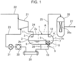
- FIG. 1 which is a block diagram of the periphery of an oil-cooled compressor, an oil separate and collect device 1 is provided on the downstream side of an oil-cooled compressor 21.
- a suction opening of the oil-cooled compressor 21 is connected with a suction flow path 22. Gas to be compressed is introduced through the suction flow path 22 into the compressor 21.
- the oil-cooled compressor 21 compresses gas introduced through the suction flow path 22. As a result, the pressure of the gas rises.
- Used for the oil-cooled compressor 21 is oil aimed at cooling and lubricating of the device, and sealing of compressed gas at a rotor part.
- a part on the upstream side of the rotor part in the compressor 21 is connected with an oil supply flow path 23. Oil is injected through the oil supply flow path 23 into the oil-cooled compressor 21. This causes the oil to be accompanied by gas which is to be compressed.
- Gas, which has been compressed (compressed gas) contains the oil and is discharged through an outlet of the oil-cooled compressor 21.
- the gas containing the oil flows through a discharge flow path 24 connected with the outlet and is supplied to the oil separate and collect device 1.
- the oil is separated and collected from compressed gas, which has been supplied, using a mass difference.
- Compressed gas from which the oil has been separated and collected, is ejected from the oil separate and collect device 1.
- Compressed gas, which has been ejected from the oil separate and collect device 1 flows through an eject flow path 25 and is supplied to an oil separator 26.
- the oil separator 26 is provided with an oil separating element (filter) 26a, and catches the oil remaining in the compressed gas.
- Compressed gas, from which the remaining oil has been separated flows through a supply flow path 27 and is transferred to a downstream process.
- the oil collected in the oil separate and collect device 1 is once retained in the oil separate and collect device 1.
- the oil retained in the oil separate and collect device 1 is ejected through an oil outlet, which is provided at a lower part, to an oil circulation path 28.
- This oil flows through the oil circulation path 28 and is transferred to a lubricating oil cooler 29.
- the lubricating oil cooler 29 cools the oil.
- the oil cooled at the lubricating oil cooler 29 flows through the oil supply flow path 23 and is filtered by a passing oil filter 30, the pressure of the oil is raised at a lubricating oil pump 31, and then the oil is supplied again to the rotor part of the oil-cooled compressor 21.
- the oil separate and collect device 1 has a horizontally elongated container body 2, which is disposed in a horizontal orientation and is made of metal.
- the container body 2 is formed of a cylindrical body with both ends being closed. That is, the container body 2 has: a cylindrical drum part 2a; a first end wall 2b, which is connected with one end part of the drum part 2a so as to close one end opening of the drum part 2a; and a second end wall 2c, which is connected with the other end part of the drum part 2a so as to close the other end opening of the drum part 2a.
- first end wall 2b and the second end wall 2c may be each formed in a flat-plate shape, the first end wall 2b and the second end wall 2c of this embodiment are each formed in a curved shape which expands outward.
- An upper space above the container body 2 can be utilized as an installation space for the oil-cooled compressor 21 or the like.
- a gas inlet 3, through which the compressed gas containing the oil flows into the container body 2, is located at an upper part on one end side (first end wall 2b side) of the interior of the container body 2.
- a gas outlet 4 through which the compressed gas from which the oil has been separated flows out of the container body 2, is located at an upper part on the other end side (second end wall 2c side) of the interior of the container body 2.
- the gas inlet 3 is constituted of an opening on the downstream side of an elbow inflow pipe 11.
- the gas outlet 4 is constituted of an opening on the upstream side of an elbow outflow pipe 12.
- a partition board 5 configured to divide the internal space of the container body 2 into a first chamber 6, which is a space on a gas inlet 3 side, and a second chamber 7, which is a space on a gas outlet 4 side, is provided at a lower part of the internal space.
- the partition board 5 is fixed to an inner surface of the drum part 2a over an area from a lower part to a side part of the drum part 2a, and stands upright in the internal space.
- the oil separated from the compressed gas accumulates mainly in the first chamber 6. Consequently, little oil accumulates in the second chamber 7.
- the compressed gas, which has flown into the container body 2, is sprayed to the first chamber 6.
- the distance between the gas outlet 4 and the oil level of the oil, which has accumulated in the container body 2 becomes small in the horizontally elongated container body 2. Therefore, the generated oil droplets and oil bubbles are carried on flow of the compressed gas around the gas outlet 4 and flow out of the container body 2 through the gas outlet 4. Therefore, the oil separation efficiency of the oil separate and collect device 1 lowers.
- an area on the gas outlet 4 side of a lower part of the interior of the container body 2 is formed as the second chamber 7 where little oil accumulates.
- This increases the distance between the gas outlet 4 and the oil level of the first chamber 6. Consequently, it is possible to prevent the generated oil droplets and oil bubbles from being sucked into the gas outlet 4.
- Some of the generated oil droplets and oil bubbles are carried on the flow of the compressed gas and are scattered from the oil level.
- the compressed gas passes through an upper part of the second chamber 7, turns along the inner surface of the second end wall 2c of the container body 2, and flows in the second chamber 7 toward the partition board 5. Since the oil droplets and oil bubbles have large inertial force, the oil droplets and oil bubbles move straight toward the partition board 5.
- a demister (trapping means) 8 configured to trap the oil bubbles is provided at a lower part of the second chamber 7.
- Most of the oil bubbles generated at the oil level of the first chamber 6 cannot climb over the height of the partition board 5 and disappear after lapse of a certain period of time. However, some of the oil bubbles may possibly pass through an upper end of the partition board 5 when the oil increases in volume, and flow into the second chamber 7. Oil bubbles, which have climbed over the partition board 5, may possibly be carried on the flow of the compressed gas and flow out through the gas outlet 4.
- the demister 8 is provided at the lower part of the second chamber 7. Since the oil bubbles, which have passed through the partition board 5, are trapped by the demister 8, it is possible to prevent re-scattering of the oil bubbles.
- a bottom part of the second chamber 7 is connected with a pipe line 10.
- a float valve 9 configured to open and close the pipe line 10 is provided at the bottom part of the second chamber 7.
- the float valve 9 is constructed to open the pipe line 10 when a certain amount of oil accumulates on the bottom part of the second chamber 7, so that the oil flows out of the container body 2 through the pipe line 10.
- the oil which has passed through the float valve 9 and flown out, flows through the pipe line 10 and joins the oil circulation path 28.
- the oil droplets and oil bubbles trapped by the partition board 5 and the demister 8 accumulate on the bottom part of the second chamber 7. Since the amount of the oil droplets and oil bubbles increases with lapse of time, the oil droplets and oil bubbles are carried again on the flow of the compressed gas and flow out through the gas outlet 4 when a certain amount of the oil droplets and oil bubbles accumulates. Moreover, the oil droplets and oil bubbles may possibly flow out through the gas outlet 4 when the oil level of the oil, which has accumulated on the bottom part of the second chamber 7, reaches the gas outlet 4.
- the float valve 9 provided at the bottom part of the second chamber 7 is constructed to cause the oil to flow out of the container body 2 when a certain amount or more of the oil accumulates on the bottom part of the second chamber 7. This can prevent the oil, which has accumulated on the bottom part of the second chamber 7, from flowing out through the gas outlet 4.
- the elbow inflow pipe 11 is provided in the container body 2.
- the elbow inflow pipe 11 is an inflow pipe, through which the compressed gas that contains the oil and has flown through the discharge flow path 24 flows into the container body 2.
- the elbow inflow pipe 11 is fixed to the container body 2 so that the compressed gas containing the oil flows into the container body 2 along a direction which does not face the oil level of the first chamber 6.
- the gas inlet 3 is an opening on the downstream side of the elbow inflow pipe 11.
- a gas inflow end is fixed to the drum part 2a, and a middle part is bent.
- the inflow direction of the gas is not limited to this. That is, the inflow direction of the compressed gas, i.e., a direction in which the gas inlet 3 opens, may be any direction other than a direction which faces the oil level of the oil that have accumulated in the first chamber 6, and may be a direction parallel to the oil level (i.e., horizontal direction), for example.
- the present invention is not limited to a structure in which a bent elbow inflow pipe 11 is provided as an inflow pipe, as long as a structure is provided in which the compressed gas is caused to flow in along a direction other than the direction which faces the oil level.
- the elbow inflow pipe 11 prevents the compressed gas from being sprayed directly to the oil level of the first chamber 6, so that it becomes possible to suppress billowing of the oil level of the first chamber 6 and reduce the generation amount of the oil droplets and oil bubbles.
- the elbow outflow pipe 12 is provided in the container body 2.
- the compressed gas in the container body 2 flows out of the container body 2 from the second end wall 2c side on the gas outlet 4 side (the other end side) through the elbow outflow pipe 12.
- the elbow outflow pipe 12 has: a first section which penetrates the drum part 2a of the container body 2; and a second section which is bent from the first section toward the second end wall 2c.
- the gas outlet 4 is an opening on the upstream side of the second section of the elbow outflow pipe 12. Since the elbow outflow pipe 12 is formed in a bent shape, the gas outlet 4 is disposed at a position far from the partition board 5. It is to be noted that an outflow pipe having a straight shape may be provided instead of the elbow outflow pipe 12 having a bent shape.
- the elbow outflow pipe 12 is provided so as to keep the entrance of the gas outlet 4 far from the oil level of the first chamber 6, so that it becomes possible to reduce the scattering amount of the oil droplets and oil bubbles, which are carried on the flow of the compressed gas and flow out.
- the height of an oil level 6a of the first chamber 6 is set equal to or smaller than 0.5 ⁇ D, assuming that the drum diameter of the container body 2 (the inner diameter of the drum part 2a) is ⁇ D (mm).
- the height L1 (mm) of the partition board 5 from a lower end of the inner surface of the drum part 2a is larger than 0.5 ⁇ D.
- the second end wall 2c on the gas outlet 4 side of the container body 2 is curved to have a depth of 0.3 ⁇ D.
- the distance from a connection section of the drum part 2a and the second end wall 2c to the most protruded end of the second end wall 2c in a central axis O direction (cylinder axis direction) of the drum part 2a is set to 0.3 ⁇ D.
- An end wall on the gas inlet 3 side (first end wall 2b) of the container body 2 is also set to have a similar shape. It is to be noted that the first end wall 2b and the second end wall 2c of the container body 2 are not limited to a curved shape but may each have a flat shape.
- the partition board 5 is disposed at a position between 0 (mm) and 0.5 ⁇ D (mm) inclusive with respect to the origin. That is, the distance L2 (mm) between the origin and a surface on the first chamber 6 side of the partition board 5 is set between 0 (mm) and 0.5 ⁇ D (mm) inclusive.
- the distance L2 is smaller than 0 mm, the oil level of the first chamber 6 reaches a lower part of the gas outlet 4 as will be described later. Therefore, the distance between the gas outlet 4 and the oil level decreases, and the oil, which is carried on the flow of the compressed gas and is scattered, increases. Moreover, in a case where the distance L2 exceeds 0.5 ⁇ D, the distance between the gas outlet 4 and the oil level becomes too large. Therefore, compressed gas collides with the partition board 5 on the further upstream side, the turbulence of the compressed gas becomes large, and the oil scattered from the oil level into the compressed gas increases.
- the distance L2 is set between 0 (mm) and 0.5 ⁇ D (mm) inclusive, so that it becomes possible to form the flow of the compressed gas, with which the oil droplets and oil bubbles hardly flow out through the gas outlet 4, around the gas outlet 4. This can further improve the oil trapping performance.
- the height L1 (mm) of the partition board 5 is larger than the height of the oil level 6a of the first chamber 6 and equal to or smaller than 0.8 ⁇ D (mm).
- the compressed gas the compressed gas around the oil level where the oil is mainly scattered
- the height L1 of the partition board 5 is set equal to or smaller than 0.8 ⁇ D (mm). This can suitably suppress the oil droplets and oil bubbles from being carried on the flow of the compressed gas around the gas outlet 4 and flowing out through the gas outlet 4.
- the compressed gas can be suitably turned along the inner surface of the container body 2 as illustrated by the arrow in FIG. 2 , it is possible to cause the oil droplets and oil bubbles, which are moved straight by the action of inertial force, to collide with the partition board 5 from the second chamber 7 side. This can suitably trap the oil droplets and oil bubbles.
- the part B, which is closest to the first chamber 6, of the inner edge of the opening edge of the gas outlet 4 is disposed at a position 0.7 ⁇ D (mm) or more away from a side wall (second end wall 2c) on the gas outlet 4 side of the container body 2. That is, in the cylinder axis direction of the drum part 2a, the distance L3 (mm) between the part B, which is closest to the first chamber 6, of the inner edge of the opening edge of the gas outlet 4 and the side wall (second end wall 2c) on the gas outlet 4 side of the container body 2 is set equal to or larger than 0.7 ⁇ D (mm).
- the part B, which is closest to the first chamber 6, of the inner edge of the opening edge of the gas outlet 4 is the lowest part of the central axis direction end part of the inner edge of the gas outlet 4.
- This causes compressed gas to flow through an upper part of the second chamber 7, descend along the inner surface of the second end wall 2c of the container body 2, and suitably form turning flow toward the partition board 5 as illustrated by the arrow in FIG. 2 .
- the oil droplets and oil bubbles which are moved straight by the action of inertial force, to collide with the partition board 5 and suitably trap the oil droplets and oil bubbles, and it is therefore possible to further improve the oil separation performance.
- the oil trapping performance was evaluated by setting the thickness of the partition board 5 to 6 mm and varying the height L1 (mm) of the partition board 5 and the distance L2 (mm) in FIG. 2 . Moreover, evaluation was also made regarding different conditions of the distance L3 (mm) or a condition without the partition board 5. Table 1 shows fifteen types of conditions for which evaluation was made.
- the inner diameter ⁇ D of the drum part 2a of the container body 2 was set to 254 mm
- the length in the horizontal direction of the first chamber 6 was set to 2,000 mm
- the inner diameter ⁇ d of the gas inlet 3 and the gas outlet 4 was set to 60 mm.
- the height of the oil level of the first chamber 6 was set to 0.5 ⁇ D. This is because the height of the oil level of the first chamber 6 is generally designed to be 0.5 ⁇ D from the trade-off relation between the retention time of lubricating oil and the size of the container body 2.
- air having a temperature of 50°C, a pressure of 2.0 MPaG, and a mean velocity of 0.48 m/s in the container body 2 was made to flow as compressed gas.
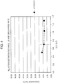
- FIGS. 3 and 4 A method of arranging droplets each having a diameter of 10 ⁇ m at regular intervals on the oil level of the first chamber 6 and comparing possibilities (discharge rates) of flowing out through the gas outlet 4 of these oil droplets regarding the above fifteen conditions was performed as an evaluation method of the oil trapping performance. The result thereof is shown in FIGS. 3 and 4 .
- FIG. 3 is a view illustrating the relation of the height L1 and the distance L2 to the discharge rate.
- FIG. 4 is a view illustrating the relation between the distance L3 and the discharge rate.
- the discharge rate of the oil droplets i.e., the oil scattering amount
- the discharge rate was further reduced when the height L1 of the partition board 5 was set within the range of 0.6 ⁇ D ⁇ L1 ⁇ 0.8 ⁇ D
- the distance L2 between the origin and the partition board 5 was set within the range of 0 ⁇ L2 ⁇ 0.5 ⁇ D
- the distance L3 between the part B, which is closest to the first chamber 6, of the inner edge of the opening edge of the gas outlet 4 and the side wall on the gas outlet 4 side of the container body 2 was set within the range of L3 ⁇ 0.7 ⁇ D.
- the effect becomes small in a case where the distance L2 between the origin and the partition board 5 is smaller than 0 because the oil level of the first chamber 6 reaches a part below the gas outlet 4 in a case where the distance L2 is smaller than 0.
- the distance between the gas outlet 4 and the oil level becomes small, and the oil, which is carried on the flow of the compressed gas and is scattered, increases.
- the effect becomes small in a case where the distance L2 exceeds 0.5 ⁇ D because the distance between the gas outlet 4 and the oil level becomes too large in a case where the distance L2 exceeds 0.5 ⁇ D.
- the compressed gas collides with the partition board 5 on a further upstream side, and therefore the turbulence of the compressed gas becomes large, and the oil, which is scattered from the oil level into the compressed gas, increases.
- pressure conditions of the compressed gas are set only to 2.0 MPaG in this evaluation, it is to be noted that an effect by the partition board 5 can be obtained under any pressure condition, since the relation between the position of the partition board 5 and the discharge rate does not vary even in different pressure conditions.
- the partition board 5 divides the lower part of a space in the container body 2 into the first chamber 6 on the gas inlet 3 side and the second chamber 7 on the gas outlet 4 side. This causes the oil separated from the compressed gas to accumulate mainly in the first chamber 6, and little oil accumulates in the second chamber 7.
- the compressed gas which has flown into the container body 2 is sprayed to the first chamber 6, the oil level of the oil, which has accumulated in the first chamber 6, bubbles, oil droplets are generated from the oil level, and bubbles including the oil are generated at the oil level.
- the height position of the oil level of the first chamber 6 and the height position of the gas outlet 4 are close to each other. Therefore, the generated oil droplets and oil bubbles are carried on the flow of the compressed gas around the gas outlet 4 and flow out through the gas outlet 4. This lowers the oil separation efficiency of the oil separate and collect device 1.
- the distance between the oil level of the first chamber 6 and the gas outlet 4 becomes large. It is therefore possible to prevent the generated oil droplets and oil bubbles from being sucked into the gas outlet 4.
- Some of the generated oil droplets or oil bubbles are carried on the flow of the compressed gas and are scattered from the oil level.
- a part of the compressed gas passes through an upper part of the second chamber 7, turns along an inner surface of a side wall of the container body 2, and flows in the second chamber 7 toward the partition board 5.
- oil droplets and oil bubbles having large inertial force move straight toward the partition board 5. Therefore, the oil droplets and oil bubbles collide with the partition board 5 and are separated from the compressed gas. This makes it possible to trap oil droplets and oil bubbles carried on the flow of the compressed gas.
- the distance L2 between the origin (the position of the part B in FIG. 2 ) and the partition board 5 is set between 0 (mm) and 0.5 ⁇ D (mm) inclusive.
- the distance L2 is smaller than 0 mm, the oil level of the first chamber 6 reaches a part below the gas outlet 4, and therefore the distance between the gas outlet 4 and the oil level becomes small. Therefore, the oil, which is carried on the flow of the compressed gas and is scattered, increases.
- the distance L2 exceeds 0.5 ⁇ D, the distance between the gas outlet 4 and the oil level becomes too large, and the compressed gas collides with the partition board 5 on a further upstream side.
- the distance L2 is set between 0 (mm) and 0.5 ⁇ D (mm) inclusive, so that flow of compressed gas, with which the oil droplets and oil bubbles hardly flow out through the gas outlet 4, can be formed around the gas outlet 4. This can further improve the oil trapping performance.
- the height of the partition board 5 is set larger than the height of the oil level 6a of the oil, which has accumulated in the first chamber 6, and equal to or smaller than 0.8 ⁇ D (mm).
- the compressed gas the compressed gas around the oil level where the oil is mainly scattered
- the height L1 of the partition board 5 is set equal to or smaller than 0.8 ⁇ D (mm), so that it becomes possible to suitably suppress the oil droplets and oil bubbles from being carried on the flow of the compressed gas around the gas outlet 4 and flowing out through the gas outlet 4.
- the compressed gas can be suitably turned along the side wall of the container body 2 as illustrated by the arrow in FIG. 2 . It is therefore possible to cause the oil droplets and oil bubbles, which are moved straight by the action of inertial force, to collide with the partition board 5 and suitably trap the oil droplets and oil bubbles.
- the distance L3 between the part B, which is closest to the first chamber 6, of the inner edge of the opening edge of the gas outlet 4 and the side wall (second end wall 2c) on the gas outlet 4 side of the container body 2 in the central axis O direction of the container body 2 is set equal to or larger than 0.7 ⁇ D (mm).
- the demister 8 configured to trap oil bubbles is provided at a lower part of the second chamber 7.
- Most of the oil bubbles generated at the oil level of the first chamber 6 cannot climb over the height of the partition board 5, and disappear after lapse of a certain period of time.
- some of the oil bubbles may possibly pass through a part above the partition board 5 when the oil increases in volume, and flow into the second chamber 7.
- oil bubbles, which have passed through the partition board 5, may possibly be carried on the flow of the compressed gas and flow out through the gas outlet 4.
- the demister 8 is provided at the lower part of the second chamber 7, so that it becomes possible to trap the oil bubbles, which have passed through the partition board 5, and prevent re-scattering of the oil bubbles.
- the float valve 9 is provided at the bottom part of the second chamber 7.
- the oil droplets and oil bubbles trapped by the partition board 5 and the demister 8 accumulate on the bottom part of the second chamber 7. Since the amount of the oil droplets and oil bubbles increases with lapse of time, the oil droplets and oil bubbles are carried again on the flow of the compressed gas and flow out through the gas outlet 4 when a certain amount of the oil droplets and oil bubbles accumulates. Moreover, the oil droplets and oil bubbles may possibly flow out through the gas outlet 4 when the oil level of the oil, which has accumulated on the bottom part of the second chamber 7, reaches the gas outlet 4.
- the float valve 9 is provided at the bottom part of the second chamber 7. This can cause the oil, which has accumulated on the bottom part of the second chamber 7, to flow out of the container body 2 and prevent the oil, which has accumulated on the bottom part of the second chamber 7, from flowing out through the gas outlet 4.
- the elbow inflow pipe 11 is provided in the container body 2.
- the elbow inflow pipe 11 causes the compressed gas containing the oil to flow into the container body 2 along a direction which does not face the liquid level of the first chamber 6.
- the elbow inflow pipe 11 is constructed to prevent the compressed gas from being sprayed directly to the oil in the first chamber 6, so that it becomes possible to suppress the oil level of the first chamber 6 from billowing and reduce the generation amount of the oil droplets and oil bubbles.
- the elbow outflow pipe 12 is provided in the container body 2.
- the elbow outflow pipe 12 causes the compressed gas in the container body 2 to flow out of the container body 2 from the side wall on the gas outlet 4 side.
- the gas outlet 4 is positioned close to the oil level of the first chamber 6, the oil droplets and oil bubbles may possibly be carried on the flow of the compressed gas and flow out through the gas outlet 4.
- the entrance of the gas outlet 4 is kept far from the oil level of the first chamber 6 by the elbow outflow pipe 12, so that it becomes possible to reduce the scattering amount of the oil droplets and oil bubbles, which are carried on the flow of the compressed gas and flow out.
- the partition board divides the lower part of the space in the container body into the first chamber on the gas inlet side and the second chamber on the gas outlet side. This causes the oil, which has been separated from compressed gas, to accumulate mainly in the first chamber, and little oil accumulates in the second chamber.
- the compressed gas which has flown into the container body is sprayed to the first chamber, the oil level of the oil, which has accumulated in the first chamber, bubbles, oil droplets are generated from the oil level, and bubbles including the oil are generated at the oil level.
- the height position of the oil level of the first chamber and the height position of the gas outlet are close to each other.
- the generated oil droplets and oil bubbles are carried on the flow of the compressed gas around the gas outlet and flow out through the gas outlet. This lowers the oil separation efficiency of the oil separate and collect device.
- the distance between the oil level of the first chamber and the gas outlet becomes large. It is therefore possible to prevent the generated oil droplets and oil bubbles from being sucked into the gas outlet.
Landscapes
- Engineering & Computer Science (AREA)
- Mechanical Engineering (AREA)
- General Engineering & Computer Science (AREA)
- Chemical & Material Sciences (AREA)
- Physics & Mathematics (AREA)
- Thermal Sciences (AREA)
- Analytical Chemistry (AREA)
- Power Engineering (AREA)
- Chemical Kinetics & Catalysis (AREA)
- Life Sciences & Earth Sciences (AREA)
- Hydrology & Water Resources (AREA)
- Environmental & Geological Engineering (AREA)
- Water Supply & Treatment (AREA)
- Organic Chemistry (AREA)
- Applications Or Details Of Rotary Compressors (AREA)
- Compressor (AREA)
- Lubrication Details And Ventilation Of Internal Combustion Engines (AREA)
- Separating Particles In Gases By Inertia (AREA)
Applications Claiming Priority (2)
| Application Number | Priority Date | Filing Date | Title |
|---|---|---|---|
| JP2015141102A JP6553435B2 (ja) | 2015-07-15 | 2015-07-15 | 油分離回収器 |
| PCT/JP2016/068041 WO2017010226A1 (ja) | 2015-07-15 | 2016-06-17 | 油分離回収器 |
Publications (2)
| Publication Number | Publication Date |
|---|---|
| EP3301382A1 true EP3301382A1 (de) | 2018-04-04 |
| EP3301382A4 EP3301382A4 (de) | 2019-01-23 |
Family
ID=57756974
Family Applications (1)
| Application Number | Title | Priority Date | Filing Date |
|---|---|---|---|
| EP16824206.3A Withdrawn EP3301382A4 (de) | 2015-07-15 | 2016-06-17 | Ölabscheider/-kollektor |
Country Status (6)
| Country | Link |
|---|---|
| US (1) | US10626860B2 (de) |
| EP (1) | EP3301382A4 (de) |
| JP (1) | JP6553435B2 (de) |
| CN (1) | CN107709899B (de) |
| BR (1) | BR112018000626B1 (de) |
| WO (1) | WO2017010226A1 (de) |
Families Citing this family (3)
| Publication number | Priority date | Publication date | Assignee | Title |
|---|---|---|---|---|
| JP6850238B2 (ja) * | 2017-10-18 | 2021-03-31 | 株式会社神戸製鋼所 | 気液分離器及び油冷式圧縮機 |
| CN114576892B (zh) * | 2020-11-30 | 2025-01-17 | 麦克维尔空调制冷(苏州)有限公司 | 一种压缩制冷系统用油分离器 |
| US20240173649A1 (en) * | 2022-11-28 | 2024-05-30 | Ronald Williams | Methods to drawdown pipe sections with the use or regulation control of flaring and cross-compression technique |
Family Cites Families (17)
| Publication number | Priority date | Publication date | Assignee | Title |
|---|---|---|---|---|
| JPS498323Y1 (de) * | 1970-01-21 | 1974-02-27 | ||
| JPS5313964Y2 (de) * | 1972-11-16 | 1978-04-14 | ||
| JPS5044959U (de) * | 1973-08-24 | 1975-05-07 | ||
| JPS565030Y2 (de) * | 1976-03-08 | 1981-02-03 | ||
| JPS6119691U (ja) * | 1984-07-10 | 1986-02-04 | 株式会社神戸製鋼所 | 油冷式圧縮機 |
| JPH0763427A (ja) * | 1993-08-30 | 1995-03-10 | Kobe Steel Ltd | 冷凍装置 |
| JP3163312B2 (ja) * | 1994-10-06 | 2001-05-08 | 三菱電機株式会社 | 冷凍サイクル用のアキュムレータ並びにその製造方法 |
| US5415776A (en) * | 1994-05-02 | 1995-05-16 | Northland Production Testing Ltd. | Horizontal separator for treating under-balance drilling fluid |
| JPH08159581A (ja) * | 1994-12-09 | 1996-06-21 | Hitachi Ltd | スクリュー冷凍機の油分離器 |
| JPH11125184A (ja) * | 1997-08-21 | 1999-05-11 | Kobe Steel Ltd | 油冷式圧縮機の油分離器 |
| JP3624110B2 (ja) | 1999-02-10 | 2005-03-02 | 株式会社神戸製鋼所 | 油冷式圧縮機の横置き型油分離回収器 |
| US6880360B2 (en) * | 2002-10-03 | 2005-04-19 | York International Corporation | Compressor systems for use with smokeless lubricant |
| US7686859B2 (en) * | 2005-08-04 | 2010-03-30 | Johnson Controls Technology Company | Coalescing filter element with drainage mechanism |
| US8187370B2 (en) | 2006-07-13 | 2012-05-29 | Shi-Apd Cryogenics, Inc. | Horizontal bulk oil separator |
| CN202289617U (zh) * | 2011-10-19 | 2012-07-04 | 程英浩 | 一种油分离回收设备 |
| US20130255308A1 (en) * | 2012-03-29 | 2013-10-03 | Johnson Controls Technology Company | Chiller or heat pump with a falling film evaporator and horizontal oil separator |
| JP2014044006A (ja) * | 2012-08-27 | 2014-03-13 | Kobe Steel Ltd | 油分離器及び圧縮装置 |
-
2015
- 2015-07-15 JP JP2015141102A patent/JP6553435B2/ja active Active
-
2016
- 2016-06-17 BR BR112018000626-2A patent/BR112018000626B1/pt not_active IP Right Cessation
- 2016-06-17 CN CN201680038838.7A patent/CN107709899B/zh active Active
- 2016-06-17 WO PCT/JP2016/068041 patent/WO2017010226A1/ja not_active Ceased
- 2016-06-17 US US15/741,988 patent/US10626860B2/en active Active
- 2016-06-17 EP EP16824206.3A patent/EP3301382A4/de not_active Withdrawn
Also Published As
| Publication number | Publication date |
|---|---|
| JP2017020761A (ja) | 2017-01-26 |
| EP3301382A4 (de) | 2019-01-23 |
| US20180202425A1 (en) | 2018-07-19 |
| BR112018000626A2 (pt) | 2018-09-18 |
| CN107709899A (zh) | 2018-02-16 |
| BR112018000626B1 (pt) | 2023-03-21 |
| JP6553435B2 (ja) | 2019-07-31 |
| WO2017010226A1 (ja) | 2017-01-19 |
| CN107709899B (zh) | 2020-01-10 |
| US10626860B2 (en) | 2020-04-21 |
Similar Documents
| Publication | Publication Date | Title |
|---|---|---|
| US9221001B2 (en) | Oil mist separator | |
| CN106460735B (zh) | 进气水分离器 | |
| EP2466230A2 (de) | Ölabscheider | |
| EP2899403B1 (de) | Schraubenverdichter und kühleinheit damit | |
| US5053126A (en) | Apparatus for gas liquid separation | |
| JP5375524B2 (ja) | オイルミストセパレータ | |
| EP3301382A1 (de) | Ölabscheider/-kollektor | |
| CN201983546U (zh) | 螺旋式油分离器 | |
| CN108465301B (zh) | 气体压缩机组合式旋风折流大口径气液复分离装置 | |
| JP2018071436A (ja) | オイルミストセパレータ | |
| KR20130006372A (ko) | 공기류로부터 액체를 분리하기 위한 분리장치 | |
| US7985273B2 (en) | Device for the precipitation of liquid droplets from a gas stream | |
| CN107084016A (zh) | 一种发动机窜气排出组件 | |
| CN111256399B (zh) | 油分离器及具有其的制冷系统 | |
| JP7597594B2 (ja) | ガスクーラ | |
| CN107893686B (zh) | 一种发动机的油气预分离结构 | |
| CN100447507C (zh) | 储液器 | |
| JP2010048483A (ja) | 気液分離器並びにこれを搭載した空気圧縮装置および空気調和装置 | |
| KR102183547B1 (ko) | 오일 세퍼레이터 | |
| US9273647B2 (en) | Air filter assembly | |
| RU169135U1 (ru) | Маслоотделитель системы вентиляции картера двигателя внутреннего сгорания | |
| ES2393590T3 (es) | Sistema de separación mecánica | |
| CN107356029B (zh) | 冷凝器壳管和制冷设备 | |
| CN208330746U (zh) | 空气压缩机 | |
| JPWO2015107610A1 (ja) | 気液分離器及びそれを備える空気圧縮機 |
Legal Events
| Date | Code | Title | Description |
|---|---|---|---|
| STAA | Information on the status of an ep patent application or granted ep patent |
Free format text: STATUS: THE INTERNATIONAL PUBLICATION HAS BEEN MADE |
|
| PUAI | Public reference made under article 153(3) epc to a published international application that has entered the european phase |
Free format text: ORIGINAL CODE: 0009012 |
|
| STAA | Information on the status of an ep patent application or granted ep patent |
Free format text: STATUS: REQUEST FOR EXAMINATION WAS MADE |
|
| 17P | Request for examination filed |
Effective date: 20171227 |
|
| AK | Designated contracting states |
Kind code of ref document: A1 Designated state(s): AL AT BE BG CH CY CZ DE DK EE ES FI FR GB GR HR HU IE IS IT LI LT LU LV MC MK MT NL NO PL PT RO RS SE SI SK SM TR |
|
| AX | Request for extension of the european patent |
Extension state: BA ME |
|
| DAV | Request for validation of the european patent (deleted) | ||
| DAX | Request for extension of the european patent (deleted) | ||
| A4 | Supplementary search report drawn up and despatched |
Effective date: 20190104 |
|
| RIC1 | Information provided on ipc code assigned before grant |
Ipc: F25B 31/00 20060101ALI20181220BHEP Ipc: F25B 43/02 20060101AFI20181220BHEP Ipc: F25B 43/00 20060101ALI20181220BHEP Ipc: F04B 39/04 20060101ALI20181220BHEP |
|
| GRAP | Despatch of communication of intention to grant a patent |
Free format text: ORIGINAL CODE: EPIDOSNIGR1 |
|
| STAA | Information on the status of an ep patent application or granted ep patent |
Free format text: STATUS: GRANT OF PATENT IS INTENDED |
|
| RIC1 | Information provided on ipc code assigned before grant |
Ipc: F25B 43/00 20060101ALI20230705BHEP Ipc: F25B 31/00 20060101ALI20230705BHEP Ipc: F04B 39/04 20060101ALI20230705BHEP Ipc: F25B 43/02 20060101AFI20230705BHEP |
|
| INTG | Intention to grant announced |
Effective date: 20230720 |
|
| STAA | Information on the status of an ep patent application or granted ep patent |
Free format text: STATUS: THE APPLICATION IS DEEMED TO BE WITHDRAWN |
|
| 18D | Application deemed to be withdrawn |
Effective date: 20231201 |