EP3301411B1 - Unité de tuyau de mesure et débitmètre de masse du type coriolis - Google Patents
Unité de tuyau de mesure et débitmètre de masse du type coriolis Download PDFInfo
- Publication number
- EP3301411B1 EP3301411B1 EP17193714.7A EP17193714A EP3301411B1 EP 3301411 B1 EP3301411 B1 EP 3301411B1 EP 17193714 A EP17193714 A EP 17193714A EP 3301411 B1 EP3301411 B1 EP 3301411B1
- Authority
- EP
- European Patent Office
- Prior art keywords
- measuring tube
- transition piece
- section
- cross
- transition
- Prior art date
- Legal status (The legal status is an assumption and is not a legal conclusion. Google has not performed a legal analysis and makes no representation as to the accuracy of the status listed.)
- Active
Links
Images



Classifications
-
- G—PHYSICS
- G01—MEASURING; TESTING
- G01F—MEASURING VOLUME, VOLUME FLOW, MASS FLOW OR LIQUID LEVEL; METERING BY VOLUME
- G01F1/00—Measuring the volume flow or mass flow of fluid or fluent solid material wherein the fluid passes through a meter in a continuous flow
- G01F1/76—Devices for measuring mass flow of a fluid or a fluent solid material
- G01F1/78—Direct mass flowmeters
- G01F1/80—Direct mass flowmeters operating by measuring pressure, force, momentum, or frequency of a fluid flow to which a rotational movement has been imparted
- G01F1/84—Coriolis or gyroscopic mass flowmeters
- G01F1/8409—Coriolis or gyroscopic mass flowmeters constructional details
- G01F1/8413—Coriolis or gyroscopic mass flowmeters constructional details means for influencing the flowmeter's motional or vibrational behaviour, e.g., conduit support or fixing means, or conduit attachments
-
- G—PHYSICS
- G01—MEASURING; TESTING
- G01F—MEASURING VOLUME, VOLUME FLOW, MASS FLOW OR LIQUID LEVEL; METERING BY VOLUME
- G01F1/00—Measuring the volume flow or mass flow of fluid or fluent solid material wherein the fluid passes through a meter in a continuous flow
- G01F1/76—Devices for measuring mass flow of a fluid or a fluent solid material
- G01F1/78—Direct mass flowmeters
- G01F1/80—Direct mass flowmeters operating by measuring pressure, force, momentum, or frequency of a fluid flow to which a rotational movement has been imparted
- G01F1/84—Coriolis or gyroscopic mass flowmeters
- G01F1/8404—Coriolis or gyroscopic mass flowmeters details of flowmeter manufacturing methods
-
- G—PHYSICS
- G01—MEASURING; TESTING
- G01F—MEASURING VOLUME, VOLUME FLOW, MASS FLOW OR LIQUID LEVEL; METERING BY VOLUME
- G01F1/00—Measuring the volume flow or mass flow of fluid or fluent solid material wherein the fluid passes through a meter in a continuous flow
- G01F1/76—Devices for measuring mass flow of a fluid or a fluent solid material
- G01F1/78—Direct mass flowmeters
- G01F1/80—Direct mass flowmeters operating by measuring pressure, force, momentum, or frequency of a fluid flow to which a rotational movement has been imparted
- G01F1/84—Coriolis or gyroscopic mass flowmeters
- G01F1/845—Coriolis or gyroscopic mass flowmeters arrangements of measuring means, e.g., of measuring conduits
- G01F1/8468—Coriolis or gyroscopic mass flowmeters arrangements of measuring means, e.g., of measuring conduits vibrating measuring conduits
- G01F1/849—Coriolis or gyroscopic mass flowmeters arrangements of measuring means, e.g., of measuring conduits vibrating measuring conduits having straight measuring conduits
- G01F1/8495—Coriolis or gyroscopic mass flowmeters arrangements of measuring means, e.g., of measuring conduits vibrating measuring conduits having straight measuring conduits with multiple measuring conduits
Definitions
- the invention is based on a measuring tube unit for use in a Coriolis mass flow meter with an inlet end and an outlet end, comprising at least two measuring tubes and at least two transition pieces, one transition piece being arranged on a measuring tube at the inlet end, each measuring tube having a measuring tube cross section and each Transition piece has an adapter cross section at the inlet.
- the invention is based on a Coriolis mass flow meter with at least one measuring tube unit with an inlet end and an outlet end, the measuring tube unit having at least two measuring tubes and at least two transition pieces, each with a transition piece being arranged on a measuring tube at the inlet end of the measuring tube unit, each of which Measuring tube has a measuring tube cross section and each transition piece has a transition piece cross section at the inlet.
- Coriolis mass flow meters are suitable for determining the mass flow of gases and / or liquids in a particularly wide range of applications.
- To determine the mass flow rate the fact that the Coriolis force acts on the fluid to be measured when it flows through a pipe set in vibration is used.
- Coriolis mass flowmeters generally have at least one measuring tube through which a fluid flows, an oscillation generator which sets the measuring tube in vibration, and two vibration sensors, the vibration sensors being arranged at the inlet end and at the outlet end of the measuring tube. If the measuring tube is set in vibration by the vibration generator during operation, the vibration sensors of the vibration tube are detected on the inlet side and on the outlet side. If a fluid also flows through the measuring tube, the Coriolis force causes an additional force on the measuring tube. This can be measured as the phase difference between the inlet-side and the outlet-side vibration. The phase difference is proportional to the mass flow of the fluid.
- the reference point is always the flow direction of the one to be detected Fluids in the operation of the flow meter. Accordingly, the inlet end corresponds to the side of the measuring tube unit through which the fluid flows into the measuring tube unit, and the outlet end consequently corresponds to the side through which the fluid leaves the measuring tube unit.
- a particularly simple embodiment has only a single straight measuring tube.
- a further embodiment has a double tube arrangement in which the measuring tubes are excited to oscillate in opposite directions to one another.
- pipe bends for example in the form of U-tubes, are used, with designs with a single pipe bend as well as with a double pipe arrangement also being known.
- Coriolis mass flow meters are installed in existing piping systems and connected to the piping via a flange connection. If the Coriolis mass flow meter has more than one measuring tube, for example two or four measuring tubes, the fluid flow to be measured must preferably be distributed evenly over the individual measuring tubes via a flow divider.
- a holder for the housing of the flow meter which is arranged at least at the inlet end and preferably also at the outlet end of the measuring tubes, and which is at the same time designed as a flow divider.
- the holder has a connection area to a pipeline. This connection area has openings, each opening being connected to a measuring tube, for example by a welded connection.
- each holder is suitable for exactly one measuring setup, ie a certain number of measuring tubes. Different measurement setups therefore require a variety of different brackets. However, since the design of a corresponding holder is very complex, the effort to manufacture and maintain this large number of holders is particularly high.
- the above-described embodiment from the prior art has the disadvantage that the fluid to be measured has contact with at least two materials within the flow measuring device, namely the material of the holder and the material of the measuring tubes.
- the publication EP 2 650 656 A1 discloses a Coriolis mass flow meter which has an additional transition piece and a connecting piece for connecting the two measuring tubes to a pipeline, the transition piece and the connecting piece being produced from one workpiece.
- a mass flow meter, which has a corresponding transition and connection piece, also has the disadvantages set out above.
- US 5,540,106 A discloses a measuring tube unit for use in a Coriolis mass flow meter.
- US 2002/139199 A1 discloses a measuring tube unit comprising two measuring tubes and a flow divider.
- DE 10 2014 119073 A1 discloses a vibration type sensor with a housing module.
- the object is achieved by the above-mentioned measuring tube unit in that the transition piece is designed in one piece with the associated measuring tube and in that the cross-section of the transition piece differs in shape and / or size from the associated measuring tube cross-section, the measuring tubes are arranged and aligned in such a way that the transition piece cross-sections form an overall cross-section and thus a flow divider.
- each measuring tube is designed in one piece with a transition piece, the entirety of the transition pieces making it possible to connect a plurality of measuring tubes to a pipeline.
- Each transition piece is designed and arranged during operation in such a way that it conducts part of the fluid flow from the one pipeline into the associated measuring tube.
- the transition piece is a kind of inlet funnel into the associated measuring tube.
- the transition piece is designed in such a way that the cross-section of the transition piece differs in shape and / or size from the cross-section of the measuring tube.
- the transition piece in his Design on the one hand adapted to the cross-section of the one pipeline and at the same time to the measuring setup, in detail to the number of measuring pipes.
- the shape of the transition piece cross section is retained and the transition piece cross section only differs in size from the measuring tube cross section.
- the size of the transition piece cross section is retained and the transition piece cross section only differs in shape from the measuring tube cross section
- the cross-section of the transition piece usually deviates in shape and size from the cross-section of the measuring tube.
- the measuring tubes are arranged and aligned according to the invention in such a way that the transition piece cross sections of the measuring tubes form an overall cross section and thus a flow divider.
- This overall cross section can lie in one plane, but alternatively the individual transition cross sections can also form an angle with one another that is smaller or larger than 180 °.
- a flow divider is formed by the formation of the overall cross section, which advantageously means that an additional component for dividing the fluid flow to be measured can be dispensed with.
- a measuring tube unit according to the invention makes it possible, in particular, to dispense with the production of a large number of different brackets, as the transition from a pipeline to the at least two measuring tubes is provided by the measuring tube unit itself.
- the measuring tube unit according to the invention has the advantage that the fluid to be measured is in contact with only one material during operation in the flow measuring device.
- the overall cross section is circular.
- the diameter of the total cross section particularly preferably corresponds essentially to the diameter of the pipeline to be connected.
- the diameter of the total cross section essentially corresponding to the diameter of the one pipeline, particularly favorable. It is also advantageous if the shape of the overall cross section deviates slightly from a circular shape. It is conceivable, for example, if the overall cross-section has the shape of a cloverleaf or a square or represents a connection of circular segments.
- transition piece cross sections have the same shape and the same size. This configuration ensures that the fluid flow is divided evenly between the individual measuring tubes during operation.
- the transition piece cross section of at least one transition piece has the shape of a semicircle or a quarter circle or a segment of a circle.
- the shape of the cross-section of the transition piece is particularly dependent on the number of measuring tubes. If the measuring tube unit has two measuring tubes, each with a transition piece, the transition piece cross section of each transition piece is preferably semicircular. If the measuring tube unit has four measuring tubes, each with a transition piece, then the transition piece cross section of each transition piece is preferably quarter-circle-shaped. In addition, it is also advantageous if the transition piece cross sections have the shape of a circular segment or a circular section or a triangle.
- the area of the transition piece cross section is larger than the area of the associated measuring tube cross section and if the transition piece has a diameter reduction when viewed in the flow direction.
- This configuration of the measuring tube unit is used, for example, if the cross-sectional area of the one pipeline is larger than the measuring tube cross section. This is particularly the case if the measuring tube unit has at least two measuring tubes or at least four measuring tubes.
- the area of the transition piece cross section is smaller than the area of the associated measuring tube cross section and if the transition piece has an increase in diameter when viewed in the flow direction.
- This configuration is used in particular if the cross-sectional area of one pipe is smaller than the measuring pipe cross-section.
- a further embodiment of the measuring tube unit has at least two further transition pieces, one transition piece each being arranged on a measuring tube at the outlet end, each transition piece having a transition piece cross section at the outlet, the transition piece being designed in one piece with the associated measuring tube and the transition piece cross section being in its shape and / or its size deviates from the associated measuring tube cross section, the measuring tubes being arranged in such a way that the transition piece cross sections form an overall cross section.
- This embodiment has the advantage that not only on the inlet side but also on the outlet side, a fluidically advantageous transition from at least two measuring tubes to a pipeline can be ensured.
- transition piece on the outlet side in particular the cross section of the transition piece, reference is made to the features of the transition pieces arranged on the inlet side. All the configurations described below also relate to transition pieces arranged on the inlet side and on the outlet side.
- the outlet-side transition pieces are particularly preferably configured identically with the transition pieces arranged at the inlet end. Alternatively, they can also differ in particular in the shape of the transition piece cross section from the transition pieces arranged on the inlet side.
- the transition piece and the associated measuring tube are made from one workpiece.
- the transition piece is particularly preferably a deformation of the end geometry of the measuring tube, the wall thickness of the measuring tube preferably being retained.
- the transition piece and the associated measuring tube are preferably made from one tube.
- the transition piece or the unit consisting of transition piece and measuring tube is produced, for example, by a mechanical forming process. This has the advantage that the transition piece or the unit consisting of transition piece and measuring tube has particularly flowing transitions.
- the transition piece or the unit comprising the transition piece and measuring tube can be produced by means of high-pressure forming, in particular by means of internal high-pressure forming.
- This has the advantage that due to the particularly high precision of the method, the transition piece or the unit consisting of the transition piece and measuring tube also has a particularly high precision with regard to its shape and its dimension.
- the transition piece or the unit consisting of transition piece and measuring tube can also be produced by means of laser sintering or by means of a 3-D printing process.
- the advantage of these methods is that any geometry can be created, so that the geometry of the transition piece can be of any complexity.
- the transition piece or the unit consisting of the transition piece and measuring tube also has a particularly high degree of precision with regard to its shape and dimensions.
- the transition pieces adjoin one another at the end in common contact contours and are tightly connected to one another in the contact contours. This configuration ensures that the fluid to be measured cannot run past the transition pieces into the flow meter during operation.
- transition pieces are preferably connected to one another in the area of the contact contours in a form-fitting, force-fitting and / or material-fitting manner.
- the object set forth at the outset is achieved by the Coriolis mass flow measuring device mentioned at the outset in that the transition piece is designed in one piece with the associated measuring tube and in that the cross-section of the transition piece differs in shape and / or in size from the associated measuring tube cross section, wherein the measuring tubes are arranged and aligned in such a way that the transition piece cross sections form an overall cross section and thus a flow divider.
- the measuring device has one of the measuring tube units described above.
- the statements made for the respective measuring tube unit also apply to a Coriolis mass flow meter that has such a measuring tube unit.
- At least one holder with a receptacle for the measuring tube unit is present, the receptacle sealingly fitting with the measuring tube unit.
- Fig. 1 is shown an arrangement of two measuring tubes 5 and a holder 11 for receiving the housing, not shown here, of a Coriolis mass flow meter from the state of the art.
- the arrangement is suitable for connecting two measuring tubes 5 to a pipeline.
- the holder 11 has a connection area 17, the connection area 17 as a flow divider during operation dividing the fluid flow evenly between the measuring tubes 5.
- a disadvantage of the arrangement shown is that the holder 11, which also serves as a connection to the pipeline and as a flow divider, is adapted to a measuring setup, here consisting of two measuring tubes 5. Different measurement setups therefore require different brackets 11, the manufacture of which is, however, relatively complex due to their complexity.
- Fig. 2 also shows an arrangement for connecting two measuring tubes 5 to a pipeline via a holder 11 from the prior art in a sectional view.
- the connection area 17 is designed such that, as a flow divider during operation, it divides the fluid flow that flows through the connected pipeline (not shown here) onto the measuring tubes 5.
- the measuring tubes 5 are connected to the connection area 17 via a welded connection.
- the 3 and 4 each show exemplary embodiments of a measuring tube 5 and a transition piece 6a, the transition piece 6a in each case being designed in one piece with the measuring tube 5.
- the measuring tube 5 has a circular measuring tube cross section 8 and the transition piece 6a at the inlet has a transition piece cross section 9a.
- Transition piece cross section 9a shown is semicircular, in the course of the transition piece 6a this has a transition to the circular measuring tube cross section 8 of the measuring tube 5.
- This in Fig. 3 The measuring tube 5 shown is therefore suitable for use in a measuring tube unit 1 consisting of two measuring tubes 5.
- the in Fig. 4 Transition piece cross section 9a shown is configured in a quarter circle and likewise has a transition to the circular measuring tube cross section 8 of the measuring tube 5 in the course of the transition piece 6a.
- This in Fig. 4 The measuring tube 5 shown is thus suitable for use in a measuring tube unit 1 consisting of four measuring tubes 5.
- transition piece cross sections 9a and total cross sections 10a are shown.
- the transition piece cross sections 9a are designed semi-circular. Together, the transition piece cross sections 9a form an overall circular cross section 10a.
- Transitional cross sections 9a shown each have the shape of a quarter circle, the total cross section 10a also being circular.
- Transition piece cross sections 9a shown are triangular and together form an overall cross section 10a in the form of a square.
- Transition piece cross sections 9a shown have the shape of a circle segment, the total cross section 10a deviating slightly from the circular shape.
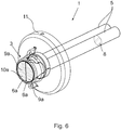
- Fig. 6 shows a first embodiment of a measuring tube unit 1 according to the invention for use in a Coriolis mass flow meter 2 with an inlet end 3 and an outlet end 4, not shown here, with two measuring tubes 5 and two transition pieces 6a, each measuring tube having a measuring tube cross section 8 and each transition piece 6a at the inlet have a transition piece cross section 9a.
- the transition pieces 6a are designed in one piece with the associated measuring tube 5; in the exemplary embodiment shown, they are made from one workpiece.
- the measuring tubes 5 are arranged in such a way that the transition piece cross-sections 9a have a circular overall cross-section 10a, which is identical to the pipeline cross-section of the pipeline not shown here.
- the two transition pieces 6a serve on the one hand to connect the two measuring tubes 5 to a pipeline and, at the same time, evenly distribute the fluid flow flowing through the pipeline to the measuring tubes 5 during operation.
- the use of a measuring tube unit 1 thus has the advantage that the holder 11 does not have to meet any special requirements with regard to the measuring setup.
- the bracket 11, which is complex to manufacture, can be used particularly flexibly.
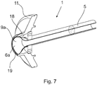
- Fig. 7 shows a sectional view of the first exemplary embodiment of the measuring tube unit 1 according to the invention, a measuring tube 5 and a transition piece 6a having a semicircular transition piece cross section 9a being shown. Also shown is a holder 11 with a receptacle 18 for the measuring tube unit 1, the receptacle 18 sealingly sealingly with the measuring tube unit 1 in the edge region 19, in detail with the transition pieces 6a.
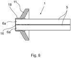
- Fig. 8 shows the first embodiment of a measuring tube unit 1 according to the invention in a sectional view in plan view.
- the transition pieces 6a adjoin one another at the end in contact contours 16 and are tightly connected to one another in the contact contours 16.
- Fig. 9 shows a first embodiment of a Coriolis mass flow measuring device 2 according to the invention with a measuring tube unit 1 with an inlet end 3 and an outlet end 4, the measuring tube unit 1 having two measuring tubes 5 and both at the inlet end 3 and at the outlet end 4 each having two transition pieces 6a, 6b, which with each measuring tube 5 are integrally connected.
- the transition pieces 6a, 6b serve to connect to a pipeline 7, through which a fluid flows in operation in the direction of the arrow 12.
- the flow measuring device 2 is connected to the external pipeline via a flange connection 13. Also shown are the housing 14 of the flow measuring device 2, in which the other components which are usually present, such as, for example, vibration generator and vibration sensor, are also arranged.
- the Coriolis mass flow meter 2 has a control and evaluation unit 15 for controlling the vibration excitation and for evaluating and displaying the recorded measurement data.
- the flow meter 2 has a holder 11 for receiving the housing 14 both on the inlet side and on the outlet side, the holder 11 likewise having a receptacle 18 for the measuring tube unit 1 and the measuring tube unit 1 being arranged in the receptacle 18.
- the illustrated embodiment of the Coriolis mass flow meter according to the invention has the advantages of a particularly simple and effective coupling of two measuring tubes 5 to a pipeline 7.
Landscapes
- Physics & Mathematics (AREA)
- Fluid Mechanics (AREA)
- General Physics & Mathematics (AREA)
- Engineering & Computer Science (AREA)
- Manufacturing & Machinery (AREA)
- Measuring Volume Flow (AREA)
Claims (15)
- Unité de tubes de mesure (1) destinée à être utilisée dans un débitmètre massique à effet Coriolis (2) comprenant une extrémité d'entrée (3) et une extrémité de sortie (4), comportant au moins deux tubes de mesure (5) et au moins deux pièces de transition (6a), dans laquelle une pièce de transition (6a) est respectivement disposée sur un tube de mesure (5) au niveau de l'extrémité d'entrée (3), dans laquelle chaque tube de mesure (5) présente une section transversale (8) de tube de mesure et chaque pièce de transition (6a) présente une section transversale (9a) de pièce de transition au niveau de l'entrée,
dans laquelle la pièce de transition (6a) est configurée d'une seule pièce avec le tube de mesure (5) associé et la section transversale (9a) de pièce de transition diffère de par sa forme et/ou sa taille de la section transversale (8) de tube de mesure associée,
caractérisée en ce que
les tubes de mesure (5) sont disposés et orientés de telle sorte que les sections transversales (9a) de pièce de transition forment une section transversale globale (10a) et donc un diviseur d'écoulement, et en ce que la pièce de transition (6a) est adaptée dans sa configuration d'une part à la section transversale de l'une des conduites tubulaires (7) à raccorder et en même temps à la configuration de mesure, en détail au nombre des tubes de mesure (5). - Unité de tubes de mesure (1) selon la revendication 1, caractérisée en ce que la section transversale globale (10a) est configurée de manière circulaire.
- Unité de tubes de mesure (1) selon l'une des revendications 1 ou 2, caractérisée en ce que les sections transversales (9a) de pièce de transition présentent la même forme et la même taille.
- Unité de tubes de mesure (1) selon l'une des revendications 1 à 3, caractérisée en ce que la section transversale (9a) de pièce de transition d'au moins une pièce de transmission (6a) présente la forme d'un demi-cercle ou d'un quart de cercle ou d'un segment de cercle.
- Unité de tubes de mesure (1) selon l'une des revendications 1 à 4, caractérisée en ce que l'aire de la section transversale (9a) de pièce de transition est supérieure à l'aire de la section transversale (8) de tube de mesure associée et en ce que la pièce de transition (6a) présente, vue dans le sens d'écoulement, une réduction de diamètre.
- Unité de tubes de mesure (1) selon l'une des revendications 1 à 4, caractérisée en ce que l'aire de la section transversale (9a) de pièce de transition est inférieure à l'aire de la section transversale (8) de tube de mesure associée et en ce que la pièce de transition (6a) présente, vue dans le sens d'écoulement, une augmentation de diamètre.
- Unité de tubes de mesure (1) selon l'une des revendications 1 à 6, caractérisée en ce qu'au moins deux autres pièces de transition (6b) sont prévues, une pièce de transition (6b) étant respectivement disposée sur un tube de mesure (5) au niveau de l'extrémité de sortie (4), chaque pièce de transition (6b) présentant une section transversale (9b) de pièce de transition au niveau de la sortie, la pièce de transition (6b) étant configurée d'une seule pièce avec le tube de mesure (5) associé et la section transversale (9b) de pièce de transition différant de par sa forme et/ou sa taille de la section transversale (8) de tube de mesure associée, les tubes de mesure (5) étant disposés de telle sorte que les sections transversales (9b) de pièce de transition forment une section transversale globale (10b).
- Unité de tubes de mesure (1) selon la revendication 7, caractérisée en ce que les pièces de transition (9b) sont configurés de manière identique aux pièces de transition (9a) disposées au niveau de l'extrémité d'entrée (3).
- Unité de tubes de mesure (1) selon l'une des revendications 1 à 8, caractérisée en ce que la pièce de transition (6a, 6b) et le tube de mesure (5) associé sont fabriqués à partir d'une pièce à travailler.
- Unité de tubes de mesure (1) selon l'une des revendications 1 à 9, caractérisée en ce que la pièce de transition (6a, 6b) ou l'unité constituée de la pièce de transition (6a, 6b) et du tube de mesure (5) est fabriquée à l'aide d'un procédé de formage mécanique, par formage à haute pression, par frittage au laser ou par un procédé de fabrication additive.
- Unité de tubes de mesure (1) selon l'une des revendications 1 à 10, caractérisée en ce que les pièces de transition (6a, 6b) sont adjacentes l'une à l'autre du côté frontal dans des contours de contact communs (16) et sont reliées de manière étanche l'une à l'autre dans les contours de contact (16).
- Unité de tubes de mesure (1) selon la revendication 11, caractérisée en ce que les pièces de transition (6a, 6b) sont reliées l'une à l'autre par complémentarité de forme, à force et/ou par liaison de matière dans la région des contours de contact (16).
- Débitmètre massique à effet Coriolis (2) comprenant au moins une unité de tubes de mesure (1) comprenant une extrémité d'entrée (3) et une extrémité de sortie (4), dans lequel l'unité de tubes de mesure (1) comporte au moins deux tubes de mesure (5) et au moins deux pièces de transition (6a), dans lequel une pièce de transition (6a) est respectivement disposée sur un tube de mesure (5) au niveau de l'extrémité d'entrée (3) de l'unité de tubes de mesure, dans lequel chaque tube de mesure (5) présente une section transversale (8) de tube de mesure et chaque pièce de transition (6a) présente une section transversale (9a) de pièce de transition au niveau de l'entrée,
dans lequel la pièce de transition (6a) est configurée d'une seule pièce avec le tube de mesure (5) associé et la section transversale (9a) de pièce de transition diffère de par sa forme et/ou sa taille de la section transversale (8) de tube de mesure associée,
caractérisé en ce que
les tubes de mesure (5) sont disposés et orientés de telle sorte que les sections transversales (9a) de pièce de transition forment une section transversale globale (10a) et donc un diviseur d'écoulement, et en ce que la pièce de transition (6a) est adaptée dans sa configuration d'une part à la section transversale de l'une des conduites tubulaires (7) à raccorder et en même temps à la configuration de mesure, en détail au nombre des tubes de mesure (5). - Débitmètre massique à effet Coriolis (2) selon la revendication 13, caractérisé en ce que l'unité de tubes de mesure (1) est configurée selon l'une des revendications 1 à 12.
- Débitmètre massique à effet Coriolis (2) selon l'une des revendications 13 ou 14, caractérisé en ce qu'un support (11) doté d'un logement (18) pour l'unité de tubes de mesure (1) est prévu, le logement (18) étant fermé de manière étanche par l'unité de tubes de mesure (1).
Applications Claiming Priority (1)
| Application Number | Priority Date | Filing Date | Title |
|---|---|---|---|
| DE102016118695.3A DE102016118695A1 (de) | 2016-10-03 | 2016-10-03 | Messrohreinheit und Coriolis-Massedurchflussmessgerät |
Publications (2)
| Publication Number | Publication Date |
|---|---|
| EP3301411A1 EP3301411A1 (fr) | 2018-04-04 |
| EP3301411B1 true EP3301411B1 (fr) | 2020-04-08 |
Family
ID=59974320
Family Applications (1)
| Application Number | Title | Priority Date | Filing Date |
|---|---|---|---|
| EP17193714.7A Active EP3301411B1 (fr) | 2016-10-03 | 2017-09-28 | Unité de tuyau de mesure et débitmètre de masse du type coriolis |
Country Status (4)
| Country | Link |
|---|---|
| US (1) | US10240958B2 (fr) |
| EP (1) | EP3301411B1 (fr) |
| CN (1) | CN107894259B (fr) |
| DE (1) | DE102016118695A1 (fr) |
Families Citing this family (6)
| Publication number | Priority date | Publication date | Assignee | Title |
|---|---|---|---|---|
| DE102016109058A1 (de) * | 2016-05-17 | 2017-11-23 | Endress+Hauser Flowtec Ag | Fluidleitungssystem |
| DE102016118016B4 (de) * | 2016-09-23 | 2021-07-15 | Krohne Ag | Coriolis-Massedurchflussmessgerät mit aktiven und passiven Messrohren |
| WO2020023056A1 (fr) * | 2018-07-27 | 2020-01-30 | Micro Motion, Inc. | Collecteur |
| EP4244584B1 (fr) | 2020-11-12 | 2025-02-19 | Endress+Hauser Flowtec AG | Diviseur de flux et système de ligne de fluide formé avec celui-ci |
| CN114459555A (zh) * | 2022-03-02 | 2022-05-10 | 沃森测控技术(河北)有限公司 | 一种非圆形截面的科氏质量流量计 |
| CN117307854A (zh) * | 2023-11-28 | 2023-12-29 | 沃森测控技术(河北)有限公司 | 分流器及科氏流量计 |
Family Cites Families (15)
| Publication number | Priority date | Publication date | Assignee | Title |
|---|---|---|---|---|
| US5540106A (en) * | 1991-01-22 | 1996-07-30 | Lew; Hyok S. | Electronic method for measuring mass flow rate |
| US5546814A (en) * | 1994-10-26 | 1996-08-20 | The Foxboro Company | Parallel-flow coriolis-type mass flowmeter with flow-dividing manifold |
| US6450042B1 (en) * | 2000-03-02 | 2002-09-17 | Micro Motion, Inc. | Apparatus for and a method of fabricating a coriolis flowmeter formed primarily of plastic |
| DE102004035971A1 (de) * | 2004-07-23 | 2006-02-16 | Endress + Hauser Flowtec Ag | Meßaufnehmer vom Vibrationstyp zum Messen von in zwei Mediumsleitungen strömenden Medien sowie In-Line-Meßgerät mit einem solchen Meßaufnehmer |
| DE102008007742A1 (de) | 2007-04-25 | 2008-11-06 | Krohne Ag | Coriolis-Massendurchflußmeßgerät |
| DE102008039867B4 (de) | 2008-08-27 | 2015-09-10 | Krohne Ag | Massedurchflußmeßgerät |
| EP2516972B1 (fr) * | 2009-12-21 | 2021-11-10 | Endress+Hauser Flowtec AG | Capteur de mesure du type à vibrations |
| DE102011006997A1 (de) * | 2011-04-07 | 2012-10-11 | Endress + Hauser Flowtec Ag | Frequenzabgleichsverfahren für eine Rohranordnung |
| DE102011006971A1 (de) * | 2011-04-07 | 2012-10-11 | Endress + Hauser Flowtec Ag | Meßwandler vom Vibrationstyp sowie Verfahren zu dessen Herstellung |
| CN104204735B (zh) * | 2012-04-03 | 2017-12-29 | 恩德斯+豪斯流量技术股份有限公司 | 振动型测量变换器 |
| JP5559239B2 (ja) * | 2012-04-26 | 2014-07-23 | 株式会社オーバル | コリオリ流量計 |
| CN204007742U (zh) * | 2014-07-31 | 2014-12-10 | 北京天辰博锐科技有限公司 | 科氏质量流量传感器 |
| DE102014118367A1 (de) * | 2014-12-10 | 2016-06-16 | Endress+Hauser Flowtec Ag | Meßaufnehmer vom Vibrationstyp sowie damit gebildetes Meßsystem |
| DE102014119073A1 (de) * | 2014-12-18 | 2016-06-23 | Endress+Hauser Flowtec Ag | Messaufnehmer vom Vibrationstyp |
| DE102016118016B4 (de) * | 2016-09-23 | 2021-07-15 | Krohne Ag | Coriolis-Massedurchflussmessgerät mit aktiven und passiven Messrohren |
-
2016
- 2016-10-03 DE DE102016118695.3A patent/DE102016118695A1/de not_active Withdrawn
-
2017
- 2017-09-28 EP EP17193714.7A patent/EP3301411B1/fr active Active
- 2017-10-03 US US15/723,288 patent/US10240958B2/en active Active
- 2017-10-09 CN CN201710928293.3A patent/CN107894259B/zh active Active
Non-Patent Citations (1)
| Title |
|---|
| None * |
Also Published As
| Publication number | Publication date |
|---|---|
| US10240958B2 (en) | 2019-03-26 |
| CN107894259B (zh) | 2020-08-04 |
| EP3301411A1 (fr) | 2018-04-04 |
| DE102016118695A1 (de) | 2018-04-05 |
| CN107894259A (zh) | 2018-04-10 |
| US20180094957A1 (en) | 2018-04-05 |
Similar Documents
| Publication | Publication Date | Title |
|---|---|---|
| EP3301411B1 (fr) | Unité de tuyau de mesure et débitmètre de masse du type coriolis | |
| EP1971800B1 (fr) | Dispositif de deviation d'un milieu s'ecoulant dans une canalisation | |
| DE102004053142B4 (de) | Flanschwirbeldurchflußmesser mit unitären zulaufenden Erweiterungsstücken | |
| EP2044392B1 (fr) | Système de mesure pour un milieu s'écoulant dans un conduit de traitement | |
| EP3306277B1 (fr) | Débitmètre à effet coriolis | |
| EP3311125B1 (fr) | Débitmètre or densimètre du type coriolis | |
| DE102011010178A1 (de) | Coriolis-Massedurchflussmessgerät | |
| EP2375224A1 (fr) | Dispositif de mesure des ultrasons et procédé de mesure de la vitesse d'écoulement d'un liquide | |
| EP3314214B1 (fr) | Débitmètre comprenant un canal de mesure et des canaux auxiliaires | |
| EP2827111B1 (fr) | Compteur à ultrasons | |
| EP3277998B1 (fr) | Conditionneur d'écoulement | |
| DE102011112028A1 (de) | Ultraschallzähler | |
| EP2072972B1 (fr) | Dispositif de mesure du mouvement d'un fluide dans un tuyau | |
| DE102017012067A1 (de) | Rohr für einen Meßwandler, Meßwandler mit einem solchen Rohr sowie damit gebildetes Meßsystem | |
| EP2502031A1 (fr) | Appareil de mesure | |
| EP2146189B1 (fr) | Mesure par ultra-sons de la vitesse d'écoulement | |
| EP3198241B1 (fr) | Dispositif de determination du débit d'un fluide comprenant une phase liquide et une phase gazeuse | |
| EP0831303B1 (fr) | Capteur de débit à tourbillon avec une grille à turbulence | |
| EP3379209A1 (fr) | Débitmètre | |
| EP2737218A1 (fr) | Redresseur d'écoulement | |
| EP2933611B1 (fr) | Débitmètre massique coriolis | |
| EP3748309B1 (fr) | Débitmètre à ultrasons, utilisation d'un débitmètre à ultrasons dans un organe d'arrêt et organe d'arrêt | |
| DE102016115426A1 (de) | Totraumfreies Messrohr für ein Messgerät sowie Verfahren zu dessen Herstellung | |
| DE102006047526A1 (de) | Strömungsgleichrichter | |
| DE102021130048A1 (de) | Messrohrsystem, Messrohr, sowie Herstellungsverfahren für ein Messrohrsystem |
Legal Events
| Date | Code | Title | Description |
|---|---|---|---|
| PUAI | Public reference made under article 153(3) epc to a published international application that has entered the european phase |
Free format text: ORIGINAL CODE: 0009012 |
|
| STAA | Information on the status of an ep patent application or granted ep patent |
Free format text: STATUS: THE APPLICATION HAS BEEN PUBLISHED |
|
| AK | Designated contracting states |
Kind code of ref document: A1 Designated state(s): AL AT BE BG CH CY CZ DE DK EE ES FI FR GB GR HR HU IE IS IT LI LT LU LV MC MK MT NL NO PL PT RO RS SE SI SK SM TR |
|
| AX | Request for extension of the european patent |
Extension state: BA ME |
|
| STAA | Information on the status of an ep patent application or granted ep patent |
Free format text: STATUS: REQUEST FOR EXAMINATION WAS MADE |
|
| 17P | Request for examination filed |
Effective date: 20181004 |
|
| RBV | Designated contracting states (corrected) |
Designated state(s): AL AT BE BG CH CY CZ DE DK EE ES FI FR GB GR HR HU IE IS IT LI LT LU LV MC MK MT NL NO PL PT RO RS SE SI SK SM TR |
|
| GRAP | Despatch of communication of intention to grant a patent |
Free format text: ORIGINAL CODE: EPIDOSNIGR1 |
|
| STAA | Information on the status of an ep patent application or granted ep patent |
Free format text: STATUS: GRANT OF PATENT IS INTENDED |
|
| GRAS | Grant fee paid |
Free format text: ORIGINAL CODE: EPIDOSNIGR3 |
|
| INTG | Intention to grant announced |
Effective date: 20191128 |
|
| GRAA | (expected) grant |
Free format text: ORIGINAL CODE: 0009210 |
|
| STAA | Information on the status of an ep patent application or granted ep patent |
Free format text: STATUS: THE PATENT HAS BEEN GRANTED |
|
| AK | Designated contracting states |
Kind code of ref document: B1 Designated state(s): AL AT BE BG CH CY CZ DE DK EE ES FI FR GB GR HR HU IE IS IT LI LT LU LV MC MK MT NL NO PL PT RO RS SE SI SK SM TR |
|
| REG | Reference to a national code |
Ref country code: CH Ref legal event code: EP Ref country code: AT Ref legal event code: REF Ref document number: 1255013 Country of ref document: AT Kind code of ref document: T Effective date: 20200415 |
|
| REG | Reference to a national code |
Ref country code: DE Ref legal event code: R096 Ref document number: 502017004614 Country of ref document: DE |
|
| REG | Reference to a national code |
Ref country code: IE Ref legal event code: FG4D Free format text: LANGUAGE OF EP DOCUMENT: GERMAN |
|
| REG | Reference to a national code |
Ref country code: NL Ref legal event code: MP Effective date: 20200408 |
|
| REG | Reference to a national code |
Ref country code: LT Ref legal event code: MG4D |
|
| PG25 | Lapsed in a contracting state [announced via postgrant information from national office to epo] |
Ref country code: NO Free format text: LAPSE BECAUSE OF FAILURE TO SUBMIT A TRANSLATION OF THE DESCRIPTION OR TO PAY THE FEE WITHIN THE PRESCRIBED TIME-LIMIT Effective date: 20200708 Ref country code: PT Free format text: LAPSE BECAUSE OF FAILURE TO SUBMIT A TRANSLATION OF THE DESCRIPTION OR TO PAY THE FEE WITHIN THE PRESCRIBED TIME-LIMIT Effective date: 20200817 Ref country code: FI Free format text: LAPSE BECAUSE OF FAILURE TO SUBMIT A TRANSLATION OF THE DESCRIPTION OR TO PAY THE FEE WITHIN THE PRESCRIBED TIME-LIMIT Effective date: 20200408 Ref country code: LT Free format text: LAPSE BECAUSE OF FAILURE TO SUBMIT A TRANSLATION OF THE DESCRIPTION OR TO PAY THE FEE WITHIN THE PRESCRIBED TIME-LIMIT Effective date: 20200408 Ref country code: SE Free format text: LAPSE BECAUSE OF FAILURE TO SUBMIT A TRANSLATION OF THE DESCRIPTION OR TO PAY THE FEE WITHIN THE PRESCRIBED TIME-LIMIT Effective date: 20200408 Ref country code: NL Free format text: LAPSE BECAUSE OF FAILURE TO SUBMIT A TRANSLATION OF THE DESCRIPTION OR TO PAY THE FEE WITHIN THE PRESCRIBED TIME-LIMIT Effective date: 20200408 Ref country code: IS Free format text: LAPSE BECAUSE OF FAILURE TO SUBMIT A TRANSLATION OF THE DESCRIPTION OR TO PAY THE FEE WITHIN THE PRESCRIBED TIME-LIMIT Effective date: 20200808 Ref country code: GR Free format text: LAPSE BECAUSE OF FAILURE TO SUBMIT A TRANSLATION OF THE DESCRIPTION OR TO PAY THE FEE WITHIN THE PRESCRIBED TIME-LIMIT Effective date: 20200709 |
|
| PG25 | Lapsed in a contracting state [announced via postgrant information from national office to epo] |
Ref country code: BG Free format text: LAPSE BECAUSE OF FAILURE TO SUBMIT A TRANSLATION OF THE DESCRIPTION OR TO PAY THE FEE WITHIN THE PRESCRIBED TIME-LIMIT Effective date: 20200708 Ref country code: RS Free format text: LAPSE BECAUSE OF FAILURE TO SUBMIT A TRANSLATION OF THE DESCRIPTION OR TO PAY THE FEE WITHIN THE PRESCRIBED TIME-LIMIT Effective date: 20200408 Ref country code: LV Free format text: LAPSE BECAUSE OF FAILURE TO SUBMIT A TRANSLATION OF THE DESCRIPTION OR TO PAY THE FEE WITHIN THE PRESCRIBED TIME-LIMIT Effective date: 20200408 Ref country code: HR Free format text: LAPSE BECAUSE OF FAILURE TO SUBMIT A TRANSLATION OF THE DESCRIPTION OR TO PAY THE FEE WITHIN THE PRESCRIBED TIME-LIMIT Effective date: 20200408 |
|
| PG25 | Lapsed in a contracting state [announced via postgrant information from national office to epo] |
Ref country code: AL Free format text: LAPSE BECAUSE OF FAILURE TO SUBMIT A TRANSLATION OF THE DESCRIPTION OR TO PAY THE FEE WITHIN THE PRESCRIBED TIME-LIMIT Effective date: 20200408 |
|
| REG | Reference to a national code |
Ref country code: DE Ref legal event code: R097 Ref document number: 502017004614 Country of ref document: DE |
|
| PG25 | Lapsed in a contracting state [announced via postgrant information from national office to epo] |
Ref country code: ES Free format text: LAPSE BECAUSE OF FAILURE TO SUBMIT A TRANSLATION OF THE DESCRIPTION OR TO PAY THE FEE WITHIN THE PRESCRIBED TIME-LIMIT Effective date: 20200408 Ref country code: DK Free format text: LAPSE BECAUSE OF FAILURE TO SUBMIT A TRANSLATION OF THE DESCRIPTION OR TO PAY THE FEE WITHIN THE PRESCRIBED TIME-LIMIT Effective date: 20200408 Ref country code: CZ Free format text: LAPSE BECAUSE OF FAILURE TO SUBMIT A TRANSLATION OF THE DESCRIPTION OR TO PAY THE FEE WITHIN THE PRESCRIBED TIME-LIMIT Effective date: 20200408 Ref country code: EE Free format text: LAPSE BECAUSE OF FAILURE TO SUBMIT A TRANSLATION OF THE DESCRIPTION OR TO PAY THE FEE WITHIN THE PRESCRIBED TIME-LIMIT Effective date: 20200408 Ref country code: SM Free format text: LAPSE BECAUSE OF FAILURE TO SUBMIT A TRANSLATION OF THE DESCRIPTION OR TO PAY THE FEE WITHIN THE PRESCRIBED TIME-LIMIT Effective date: 20200408 Ref country code: RO Free format text: LAPSE BECAUSE OF FAILURE TO SUBMIT A TRANSLATION OF THE DESCRIPTION OR TO PAY THE FEE WITHIN THE PRESCRIBED TIME-LIMIT Effective date: 20200408 Ref country code: IT Free format text: LAPSE BECAUSE OF FAILURE TO SUBMIT A TRANSLATION OF THE DESCRIPTION OR TO PAY THE FEE WITHIN THE PRESCRIBED TIME-LIMIT Effective date: 20200408 |
|
| PLBE | No opposition filed within time limit |
Free format text: ORIGINAL CODE: 0009261 |
|
| STAA | Information on the status of an ep patent application or granted ep patent |
Free format text: STATUS: NO OPPOSITION FILED WITHIN TIME LIMIT |
|
| PG25 | Lapsed in a contracting state [announced via postgrant information from national office to epo] |
Ref country code: SK Free format text: LAPSE BECAUSE OF FAILURE TO SUBMIT A TRANSLATION OF THE DESCRIPTION OR TO PAY THE FEE WITHIN THE PRESCRIBED TIME-LIMIT Effective date: 20200408 Ref country code: PL Free format text: LAPSE BECAUSE OF FAILURE TO SUBMIT A TRANSLATION OF THE DESCRIPTION OR TO PAY THE FEE WITHIN THE PRESCRIBED TIME-LIMIT Effective date: 20200408 |
|
| 26N | No opposition filed |
Effective date: 20210112 |
|
| PG25 | Lapsed in a contracting state [announced via postgrant information from national office to epo] |
Ref country code: SI Free format text: LAPSE BECAUSE OF FAILURE TO SUBMIT A TRANSLATION OF THE DESCRIPTION OR TO PAY THE FEE WITHIN THE PRESCRIBED TIME-LIMIT Effective date: 20200408 |
|
| REG | Reference to a national code |
Ref country code: BE Ref legal event code: MM Effective date: 20200930 |
|
| PG25 | Lapsed in a contracting state [announced via postgrant information from national office to epo] |
Ref country code: LU Free format text: LAPSE BECAUSE OF NON-PAYMENT OF DUE FEES Effective date: 20200928 |
|
| PG25 | Lapsed in a contracting state [announced via postgrant information from national office to epo] |
Ref country code: BE Free format text: LAPSE BECAUSE OF NON-PAYMENT OF DUE FEES Effective date: 20200930 Ref country code: IE Free format text: LAPSE BECAUSE OF NON-PAYMENT OF DUE FEES Effective date: 20200928 |
|
| PG25 | Lapsed in a contracting state [announced via postgrant information from national office to epo] |
Ref country code: TR Free format text: LAPSE BECAUSE OF FAILURE TO SUBMIT A TRANSLATION OF THE DESCRIPTION OR TO PAY THE FEE WITHIN THE PRESCRIBED TIME-LIMIT Effective date: 20200408 Ref country code: MT Free format text: LAPSE BECAUSE OF FAILURE TO SUBMIT A TRANSLATION OF THE DESCRIPTION OR TO PAY THE FEE WITHIN THE PRESCRIBED TIME-LIMIT Effective date: 20200408 Ref country code: CY Free format text: LAPSE BECAUSE OF FAILURE TO SUBMIT A TRANSLATION OF THE DESCRIPTION OR TO PAY THE FEE WITHIN THE PRESCRIBED TIME-LIMIT Effective date: 20200408 |
|
| PG25 | Lapsed in a contracting state [announced via postgrant information from national office to epo] |
Ref country code: MK Free format text: LAPSE BECAUSE OF FAILURE TO SUBMIT A TRANSLATION OF THE DESCRIPTION OR TO PAY THE FEE WITHIN THE PRESCRIBED TIME-LIMIT Effective date: 20200408 Ref country code: MC Free format text: LAPSE BECAUSE OF FAILURE TO SUBMIT A TRANSLATION OF THE DESCRIPTION OR TO PAY THE FEE WITHIN THE PRESCRIBED TIME-LIMIT Effective date: 20200408 |
|
| P01 | Opt-out of the competence of the unified patent court (upc) registered |
Effective date: 20230607 |
|
| REG | Reference to a national code |
Ref country code: AT Ref legal event code: MM01 Ref document number: 1255013 Country of ref document: AT Kind code of ref document: T Effective date: 20220928 |
|
| PG25 | Lapsed in a contracting state [announced via postgrant information from national office to epo] |
Ref country code: AT Free format text: LAPSE BECAUSE OF NON-PAYMENT OF DUE FEES Effective date: 20220928 |
|
| REG | Reference to a national code |
Ref country code: CH Ref legal event code: U11 Free format text: ST27 STATUS EVENT CODE: U-0-0-U10-U11 (AS PROVIDED BY THE NATIONAL OFFICE) Effective date: 20251001 |
|
| PGFP | Annual fee paid to national office [announced via postgrant information from national office to epo] |
Ref country code: GB Payment date: 20250919 Year of fee payment: 9 |
|
| PGFP | Annual fee paid to national office [announced via postgrant information from national office to epo] |
Ref country code: FR Payment date: 20250922 Year of fee payment: 9 |
|
| PGFP | Annual fee paid to national office [announced via postgrant information from national office to epo] |
Ref country code: DE Payment date: 20251110 Year of fee payment: 9 |
|
| PGFP | Annual fee paid to national office [announced via postgrant information from national office to epo] |
Ref country code: CH Payment date: 20251001 Year of fee payment: 9 |