EP3301414B1 - Couvercle - Google Patents
Couvercle Download PDFInfo
- Publication number
- EP3301414B1 EP3301414B1 EP17194000.0A EP17194000A EP3301414B1 EP 3301414 B1 EP3301414 B1 EP 3301414B1 EP 17194000 A EP17194000 A EP 17194000A EP 3301414 B1 EP3301414 B1 EP 3301414B1
- Authority
- EP
- European Patent Office
- Prior art keywords
- load cell
- sleeve
- housing
- housings
- load
- Prior art date
- Legal status (The legal status is an assumption and is not a legal conclusion. Google has not performed a legal analysis and makes no representation as to the accuracy of the status listed.)
- Active
Links
Images
Classifications
-
- G—PHYSICS
- G01—MEASURING; TESTING
- G01G—WEIGHING
- G01G21/00—Details of weighing apparatus
- G01G21/28—Frames, Housings
-
- G—PHYSICS
- G01—MEASURING; TESTING
- G01G—WEIGHING
- G01G21/00—Details of weighing apparatus
- G01G21/30—Means for preventing contamination by dust
Definitions
- the present invention relates to a cover for covering several load cell housings together.
- multi-track weighing systems in which products to be weighed, such as tablets, are divided into several tracks, with at least one load cell being arranged in each track.
- a load cell arrangement and checkweigher in which a monolithic weighing block is surrounded by a dirt-repellent cover arrangement, which is laterally sloping, preferably in a convex shape, from an upper apex line.
- a coupling arrangement which is guided laterally through the cover arrangement, allows a load to be introduced into the load cell block.
- the EP 1898 192 A1 shows a weighing device with load cells arranged one above the other in several planes, offset from one another. The individual load cell levels are separated from each other by a base plate acting as an intermediate floor, the base plate being penetrated by vertical cutouts through which the load cells of the lower load cells protrude upwards between the load cells arranged above the base plate and are therefore accessible.
- the arrangement of closely adjacent load cells or their load cell housings reduces the installation space required for the system, but cleaning the individual load cell housings is difficult. Particularly when manufacturing pharmaceutical products or foodstuffs, there are particularly high demands on cleanliness in the production systems, so that the housing of the load cells must also be cleaned regularly and thoroughly. If the load cell housings are arranged close together, narrow gaps are created between the housings which are difficult to clean. The housings would have to be removed for good cleaning, which would result in the temporary shutdown of individual tracks or the entire weighing system and endanger the desired high product throughput.
- the object of the invention was therefore to solve the aforementioned problem and to provide means which considerably reduce the cleaning effort of multi-track weighing systems.
- the object is achieved by a cover according to claim 1. Further advantageous embodiments result from the subclaims.
- the invention is based on the knowledge of avoiding the deposition of contaminants between adjacent load cell housings with the aid of a cover hood that protects the load cell housings together.
- at least two load cell housings are jointly covered by the cover hood in such a way that the narrow space existing between the load cell housings is secured or covered against contamination.
- the cover preferably covers all the load cell housings together and protects the entire load cell arrangement from contamination.
- a load cell of a multi-track weighing system usually comprises a load cell housing with a housing opening at the top of the housing, through which a load introduction bolt protrudes upwards in the vertical direction.
- the load introduction bolt receives a weight force to be detected and passes it on through the housing opening into the interior of the load cell housing, where the force detected is converted into a weight signal to be processed using suitable sensor means (electromagnetic force compensation with monoblock technology, strain gauges, vibrating strings, etc.) becomes.
- suitable sensor means electromechanical force compensation with monoblock technology, strain gauges, vibrating strings, etc.
- the cover according to the invention comprises an upper part which covers some or all of the load cell housings of a multi-track weighing system from above together.
- the top part contains a separate passage opening for each load introduction bolt of the load cell housing to be covered.
- the cover can be placed on the existing arrangement of load cell housings positioned next to each other from above or put on in such a way that only the load introduction bolts of the individual load cells protruding through the individual passage openings can then be seen or accessed.
- the rest of the load cell arrangement, in particular also the gaps or spaces between the individual load cell housings, remain advantageously protected against falling product residues or contaminants below the upper part or within the cover.
- the cover can expediently be connected to the individual load cell housings, the upper part preferably resting on a section of the top of the individual load cell housings in a sealing manner.
- This has several advantages.
- the sealing contact between the underside of the cover top and the top of the individual load cell housings ensures that any contaminants that enter the respective passage opening cannot get into the space between the cover and the outside of the load cell housing.
- the vertical distance between the housing openings of the individual load cell housings and the associated passage openings in the upper part of the cover is reduced to a minimum.
- the cover hood according to the invention permits the arrangement of at least two load cell housings which are covered together by the cover hood.
- the cover according to the invention can also jointly cover load cell housings that are not positioned directly or closely adjacent to one another, in which case the space between the load cell housings is also covered and protected against contamination.
- a particularly advantageous embodiment of the invention relates to an arrangement of a plurality of load cell housings which are not only covered together with the cover, but are respectively connected to it. This is done with the aid of a sleeve for each load cell housing, which protrudes both through the respective housing opening of the load cell housing and through the associated passage opening of the upper part. Fastening means engaging on the sleeve fix the top part of the cover and the respective load cell housing to one another.
- a labyrinth ring known per se is particularly suitable as the fastening means, which is to additionally complicate the penetration of contaminants into the passage opening and in particular the housing opening of the respective load cell.
- the labyrinth ring can preferably be screwed onto an external thread of the sleeve. Alternatively, it can also be formed in one piece with the sleeve.
- the arrangement according to the invention can be assembled by first fastening the respective sleeve on some or all of the load cell housings to or in the housing opening of the respective load cell, for example by screwing into an internal thread provided there.
- a flange attached to the sleeve can serve to define the screw-in height and, at the same time, to produce a positive stop between the sleeve and the load cell housing.
- the sleeve can be secured to the load cell housing against unintentional loosening.
- a securing means screw, locking pin, self-locking nut, etc.
- the covering hood according to the invention can be placed on the load cell housing in such a way that the respective sleeves protrude through the associated passage openings of the upper part.
- the load introduction bolts projecting upward from the load cell housings within the individual sleeves are then accessible from outside the cover, while the group of load cell housings is otherwise completely covered by the cover.
- the fasteners which are preferably designed as labyrinth rings, are then fastened to the section of the respective sleeves projecting upward through the cover, expediently by screwing on.
- the diameter of the respective passage opening (preferably slightly) should be larger than the outer diameter of the respective sleeve and at the same time smaller than the effective outer diameter of the labyrinth ring, so that the underside of the labyrinth ring acts against the top of the upper part. If the upper part rests on a section of the load cell housing, it can be positively clamped against the load cell housing.
- a particular advantage of the cover according to the invention is that it is designed to be compatible with multi-track weighing systems in which the individual load cell housings are equipped with a sleeve of the aforementioned type and an associated labyrinth ring as fastening means.
- the sleeve In regular operation of a load cell not covered according to the invention, the sleeve only serves to fasten the labyrinth ring on the top of the load cell housing, which is intended to prevent contaminants from penetrating into the interior of the load cell housing.
- the covering hood according to the invention can be installed or retrofitted on site with little effort as a common protection for a group of such load cell housings by a simple method.
- the covering hood according to the invention is preferably designed in such a way that a number of passage openings can be closed via blind covers in the event that not every passage opening is required.
- the covering hood can also be designed to selectively introduce individual passage openings into the upper part depending on the spatial position of the load introduction bolts, for example by loosening circular or other material sections from the upper part via predetermined breaking points.
- the cover hood can be used flexibly for different arrangements of load cell housings, be it closely adjacent to one another or with a larger spacing.
- an arrangement of load cell housings and cover additionally includes sealing means, which preferably act between the labyrinth ring and the upper part of the cover.
- sealing means which preferably act between the labyrinth ring and the upper part of the cover.
- an O-ring could be inserted into an annular groove on the underside of a labyrinth ring, which additionally seals after screwing onto the sleeve or upon contact with the top of the upper part.
- the cover can also completely cover the arrangement of the load cell housings on the sides to prevent dirt from entering from the side.
- the side walls of the cover preferably extend down to a base plate on which the load cells are arranged.
- the side protection can also end above such a base plate.
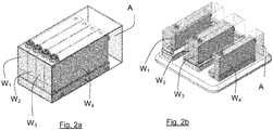
- FIG. 2a While in Fig. 2a The individual load cell housings are arranged directly adjacent to one another and only form narrow gaps between them Fig. 2b partially positioned at a greater distance from each other. Nevertheless, the (in Fig. 2b cover A shown partially interrupted, all load cell housings together and thus protects gaps and larger spaces equally against the ingress of contaminants.
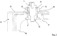
- FIG. 1 shows a schematic detailed view of the arrangements according to Fig. 2 .
- a load cell housing W has a housing opening G through which a load introduction bolt L projects to the outside of the housing W.
- the housing opening G has an unspecified internal thread, into which a sleeve H provided with a suitable external thread is screwed from below.
- a flange F arranged at the rear (lower) end of the sleeve H acts with one complementary stop surface of the load cell housing W together when the final screw-in position of the sleeve H is reached.
- a cover hood A which has a passage opening D in an upper part O, is slipped over the load cell housing W and the sleeve H or the load introduction bolt L projecting upward therefrom.
- the passage opening D is selected slightly larger than the outer diameter of the sleeve H.
- the underside of the upper part O lies on an unspecified upper side of the load cell housing W plan and thereby seals the narrow space between the outside of the load cell housing W and the inside of the cover A. .
- a simplified labyrinth ring S is screwed from above onto the upwardly projecting end of the sleeve H until it rests against the top of the upper part O. Since the sleeve H with its flange F lies against the inside of the load cell housing W, the labyrinth ring S can be screwed on to generate a pressure force on the external thread of the sleeve H between the underside of the labyrinth ring S and the upper side of the upper part O, which at the same time presses the upper part O onto the upper side of the load cell housing W.
- a circumferential groove is introduced on the underside of the labyrinth ring S, in which an O-ring R is arranged in order to additionally seal the gap between the labyrinth ring S and the upper part O.
- a locking screw P introduced into the inside of the load cell housing W acts on the underside of the flange F of the sleeve H with a flange-like extension. This ensures that the sleeve H does not unintentionally detach from the housing opening G or twist relative thereto.
Landscapes
- Physics & Mathematics (AREA)
- General Physics & Mathematics (AREA)
- Battery Mounting, Suspending (AREA)
- Measurement Of Force In General (AREA)
- Closures For Containers (AREA)
- Gasket Seals (AREA)
Claims (9)
- Capot (A) permettant de recouvrir conjointement plusieurs boîtiers de cellule de pesage (W1, W2, ...), un boulon d'application de charge (L1, L2, ...) faisant saillie à partir de chaque boîtier de cellule de pesage (W1, W2, ...) à travers une ouverture de boîtier (G1, G2),
dans lequel, dans une partie supérieure (O) du capot (A), une ouverture de passage (D1, D2, ...) particulière est prévue pour chaque boulon d'application de charge (L1, L2, ...),
caractérisé en ce que le capot (A) peut être relié aux boîtiers de cellule de pesage (W1, W2, ...) individuels. - Capot (A) selon la revendication 1, caractérisé en ce que le capot (A) peut être relié aux boîtiers de cellule de pesage (W1, W2, ...) individuels de telle sorte que la partie supérieure (O) repose de manière étanche sur une portion de la surface supérieure des boîtiers de cellule de pesage (W1, W2, ...) individuels.
- Agencement composé d'au moins deux boîtiers de cellule de pesage (W1, W2, ...) recouverts par un capot selon la revendication 1 ou 2.
- Agencement selon la revendication précédente, caractérisé en ce que chaque boîtier de cellule de pesage (W1, W2, ...) est relié au capot (A) en ce qu'une douille (H1, H2, ...) respectivement fait saillie à travers l'ouverture de boîtier (G1, G2) respective et l'ouverture de passage (D1, D2, ...) respective, dans lequel des moyens de fixation (S1, S2, ...) attaquant au niveau de la douille fixent la partie supérieure (O) et le boîtier de cellule de pesage (W1, W2, ...) respectif l'une par rapport à l'autre.
- Agencement selon la revendication précédente, caractérisé en ce que le moyen de fixation est une garniture en labyrinthe (S1, S2, ...) qui peut être vissée sur la surface supérieure de la partie supérieure (O), détournée du boîtier de cellule de pesage (W1, W2, ...), sur un filetage de la douille (H1, H2, ...) ou qui peut être réalisée d'une seule pièce avec la douille (H1, H2, ...).
- Agencement selon l'une quelconque des revendications 3 à 5, caractérisé en ce qu'un taraudage est prévu au niveau de l'ouverture de boîtier (G1, G2, ...) dans lequel la douille (H1, H2, ...) peut être vissée par l'intermédiaire d'un filetage prévu sur celle-ci.
- Agencement selon l'une quelconque des revendications 3 à 6, caractérisé en ce qu'une douille (H1, H2, ...) reliée au boîtier de cellule de pesage (W1, W2, ...) respectif est bloquée à l'aide de moyens de blocage (P) contre un déblocage non intentionnel du boîtier de cellule de pesage (W1, W2, ...).
- Agencement selon l'une quelconque des revendications 3 à 7, caractérisé en ce que la douille (H1, H2, ...) présente une bride (F) coopérant avec le boîtier de cellule de pesage (W1, W2, ...) afin de pouvoir spécifier avec précision la position de la douille (H1, H2) par rapport au boîtier de la position, la bride (F) étant réalisée d'une seule pièce avec la douille (H1, H2, ...) ou sous forme d'anneau pouvant être fixé à la douille ou pouvant être vissé sur la douille (H1, H2, ...).
- Agencement selon l'une quelconque des revendications 3 à 8, caractérisé en ce qu'une garniture en labyrinthe (S1, S2, ...) servant de moyen de fixation présente sur sa surface inférieure, tournée vers la partie supérieure (O), des moyens d'étanchéité, en particulier un joint torique s'étendant de préférence dans une rainure.
Priority Applications (1)
| Application Number | Priority Date | Filing Date | Title |
|---|---|---|---|
| PL17194000T PL3301414T3 (pl) | 2016-09-30 | 2017-09-29 | Pokrywa zakrywająca |
Applications Claiming Priority (1)
| Application Number | Priority Date | Filing Date | Title |
|---|---|---|---|
| DE202016105471.0U DE202016105471U1 (de) | 2016-09-30 | 2016-09-30 | Abdeckhaube |
Publications (2)
| Publication Number | Publication Date |
|---|---|
| EP3301414A1 EP3301414A1 (fr) | 2018-04-04 |
| EP3301414B1 true EP3301414B1 (fr) | 2020-03-18 |
Family
ID=57466659
Family Applications (1)
| Application Number | Title | Priority Date | Filing Date |
|---|---|---|---|
| EP17194000.0A Active EP3301414B1 (fr) | 2016-09-30 | 2017-09-29 | Couvercle |
Country Status (6)
| Country | Link |
|---|---|
| US (1) | US10564030B2 (fr) |
| EP (1) | EP3301414B1 (fr) |
| JP (1) | JP6513761B2 (fr) |
| DE (1) | DE202016105471U1 (fr) |
| ES (1) | ES2811319T3 (fr) |
| PL (1) | PL3301414T3 (fr) |
Family Cites Families (8)
| Publication number | Priority date | Publication date | Assignee | Title |
|---|---|---|---|---|
| CH673528A5 (fr) | 1988-02-15 | 1990-03-15 | Mettler Instrumente Ag | |
| EP1898192A1 (fr) * | 2006-09-06 | 2008-03-12 | Mettler-Toledo AG | Dispositif de pesage |
| EP1925922A1 (fr) | 2006-11-24 | 2008-05-28 | Mettler-Toledo AG | Dispositif de pesage multiple pouvant être tempéré |
| DE202008014660U1 (de) | 2008-11-05 | 2009-01-29 | Mettler-Toledo Garvens Gmbh | Wägezellenanordnung und Kontrollwaage mit einer Wägezellenanordnung |
| EP2278285B1 (fr) * | 2009-07-23 | 2014-04-30 | Mettler-Toledo AG | Capteur de charge pouvant être relié |
| JP5628526B2 (ja) | 2010-01-19 | 2014-11-19 | アンリツ産機システム株式会社 | 電子秤 |
| DE102013105647B4 (de) * | 2013-05-31 | 2014-12-11 | Wipotec Wiege- Und Positioniersysteme Gmbh | Gehäuse für eine Wägevorrichtung |
| JP6486777B2 (ja) | 2015-06-19 | 2019-03-20 | アンリツインフィビス株式会社 | 重量測定装置 |
-
2016
- 2016-09-30 DE DE202016105471.0U patent/DE202016105471U1/de active Active
-
2017
- 2017-09-28 US US15/719,462 patent/US10564030B2/en active Active
- 2017-09-29 EP EP17194000.0A patent/EP3301414B1/fr active Active
- 2017-09-29 ES ES17194000T patent/ES2811319T3/es active Active
- 2017-09-29 PL PL17194000T patent/PL3301414T3/pl unknown
- 2017-10-02 JP JP2017192861A patent/JP6513761B2/ja active Active
Non-Patent Citations (1)
| Title |
|---|
| None * |
Also Published As
| Publication number | Publication date |
|---|---|
| ES2811319T3 (es) | 2021-03-11 |
| US20180094967A1 (en) | 2018-04-05 |
| JP6513761B2 (ja) | 2019-05-15 |
| JP2018059934A (ja) | 2018-04-12 |
| DE202016105471U1 (de) | 2016-11-10 |
| PL3301414T3 (pl) | 2020-11-02 |
| EP3301414A1 (fr) | 2018-04-04 |
| US10564030B2 (en) | 2020-02-18 |
Similar Documents
| Publication | Publication Date | Title |
|---|---|---|
| EP3602708B1 (fr) | Ossature d'armoire électrique avec socle | |
| EP3153830B1 (fr) | Support de charge ayant un dispositif de verrouillage | |
| EP2808660B1 (fr) | Boîtier pour un dispositif de pesage | |
| DE102011109576A1 (de) | Bedienterminal | |
| EP3301414B1 (fr) | Couvercle | |
| WO2004046667A1 (fr) | Module de pesee pourvu d'un dispositif de depoussierage | |
| DE102012210700A1 (de) | Hygieneverbindungseinrichtung | |
| DE69832273T2 (de) | Abdeckung für druckentlastungsgerät | |
| DE102014116746B4 (de) | Modulare Laserschutzwand | |
| EP3607624B1 (fr) | Ensemble comprenant un socle et un châssis pour armoire électrique ainsi qu'une rangée d'armoires électriques | |
| EP2456291B1 (fr) | Ventilateur de toit et ventilation de toit | |
| EP3256305B1 (fr) | Coiffe de protection pour une machine de moulage par injection | |
| DE102017004959A1 (de) | Motorantriebsvorrichtung mit gebläsewartungsstruktur mit guter bedienbarkeit | |
| WO2010006459A1 (fr) | Unité siège et banc | |
| DE102013113158A1 (de) | Verschraubung eines Getriebedeckels | |
| EP2894258B1 (fr) | Protection contre les chocs | |
| EP3607615B1 (fr) | Cadre de maintien | |
| DE202007011217U1 (de) | Zugangsluke für ein Silo | |
| DE19502343C2 (de) | Feuchtigkeitsabweisende Belüftungsvorrichtung für ein Gehäuse | |
| DE102014112519A1 (de) | Abdeckelement für ein Verriegelungselement einer Küchenmaschine | |
| EP2641306B1 (fr) | Dispositif formant goulotte d'expulsion pour un limiteur de surtension, limiteur de surtension et jeu de limiteurs de surtensions montés en série | |
| EP1954930B1 (fr) | Enceinte pour chambre de combustion de type silo d'une turbine a gaz | |
| DE2208715A1 (de) | Verbindung zweier Konstruktionselemente | |
| DE20216236U1 (de) | Sockel für Geldautomaten | |
| DE3830367A1 (de) | Einrichtung zur fernmontage eines einbauteils |
Legal Events
| Date | Code | Title | Description |
|---|---|---|---|
| PUAI | Public reference made under article 153(3) epc to a published international application that has entered the european phase |
Free format text: ORIGINAL CODE: 0009012 |
|
| STAA | Information on the status of an ep patent application or granted ep patent |
Free format text: STATUS: THE APPLICATION HAS BEEN PUBLISHED |
|
| AK | Designated contracting states |
Kind code of ref document: A1 Designated state(s): AL AT BE BG CH CY CZ DE DK EE ES FI FR GB GR HR HU IE IS IT LI LT LU LV MC MK MT NL NO PL PT RO RS SE SI SK SM TR |
|
| AX | Request for extension of the european patent |
Extension state: BA ME |
|
| STAA | Information on the status of an ep patent application or granted ep patent |
Free format text: STATUS: REQUEST FOR EXAMINATION WAS MADE |
|
| 17P | Request for examination filed |
Effective date: 20181004 |
|
| RBV | Designated contracting states (corrected) |
Designated state(s): AL AT BE BG CH CY CZ DE DK EE ES FI FR GB GR HR HU IE IS IT LI LT LU LV MC MK MT NL NO PL PT RO RS SE SI SK SM TR |
|
| GRAP | Despatch of communication of intention to grant a patent |
Free format text: ORIGINAL CODE: EPIDOSNIGR1 |
|
| STAA | Information on the status of an ep patent application or granted ep patent |
Free format text: STATUS: GRANT OF PATENT IS INTENDED |
|
| INTG | Intention to grant announced |
Effective date: 20191010 |
|
| GRAS | Grant fee paid |
Free format text: ORIGINAL CODE: EPIDOSNIGR3 |
|
| GRAA | (expected) grant |
Free format text: ORIGINAL CODE: 0009210 |
|
| STAA | Information on the status of an ep patent application or granted ep patent |
Free format text: STATUS: THE PATENT HAS BEEN GRANTED |
|
| AK | Designated contracting states |
Kind code of ref document: B1 Designated state(s): AL AT BE BG CH CY CZ DE DK EE ES FI FR GB GR HR HU IE IS IT LI LT LU LV MC MK MT NL NO PL PT RO RS SE SI SK SM TR |
|
| REG | Reference to a national code |
Ref country code: GB Ref legal event code: FG4D Free format text: NOT ENGLISH |
|
| TPAC | Observations filed by third parties |
Free format text: ORIGINAL CODE: EPIDOSNTIPA |
|
| REG | Reference to a national code |
Ref country code: DE Ref legal event code: R096 Ref document number: 502017004275 Country of ref document: DE |
|
| REG | Reference to a national code |
Ref country code: AT Ref legal event code: REF Ref document number: 1246441 Country of ref document: AT Kind code of ref document: T Effective date: 20200415 Ref country code: IE Ref legal event code: FG4D Free format text: LANGUAGE OF EP DOCUMENT: GERMAN |
|
| REG | Reference to a national code |
Ref country code: NL Ref legal event code: FP |
|
| REG | Reference to a national code |
Ref country code: CH Ref legal event code: NV Representative=s name: TROESCH SCHEIDEGGER WERNER AG, CH |
|
| PG25 | Lapsed in a contracting state [announced via postgrant information from national office to epo] |
Ref country code: RS Free format text: LAPSE BECAUSE OF FAILURE TO SUBMIT A TRANSLATION OF THE DESCRIPTION OR TO PAY THE FEE WITHIN THE PRESCRIBED TIME-LIMIT Effective date: 20200318 Ref country code: FI Free format text: LAPSE BECAUSE OF FAILURE TO SUBMIT A TRANSLATION OF THE DESCRIPTION OR TO PAY THE FEE WITHIN THE PRESCRIBED TIME-LIMIT Effective date: 20200318 Ref country code: NO Free format text: LAPSE BECAUSE OF FAILURE TO SUBMIT A TRANSLATION OF THE DESCRIPTION OR TO PAY THE FEE WITHIN THE PRESCRIBED TIME-LIMIT Effective date: 20200618 |
|
| PG25 | Lapsed in a contracting state [announced via postgrant information from national office to epo] |
Ref country code: SE Free format text: LAPSE BECAUSE OF FAILURE TO SUBMIT A TRANSLATION OF THE DESCRIPTION OR TO PAY THE FEE WITHIN THE PRESCRIBED TIME-LIMIT Effective date: 20200318 Ref country code: LV Free format text: LAPSE BECAUSE OF FAILURE TO SUBMIT A TRANSLATION OF THE DESCRIPTION OR TO PAY THE FEE WITHIN THE PRESCRIBED TIME-LIMIT Effective date: 20200318 Ref country code: BG Free format text: LAPSE BECAUSE OF FAILURE TO SUBMIT A TRANSLATION OF THE DESCRIPTION OR TO PAY THE FEE WITHIN THE PRESCRIBED TIME-LIMIT Effective date: 20200618 Ref country code: GR Free format text: LAPSE BECAUSE OF FAILURE TO SUBMIT A TRANSLATION OF THE DESCRIPTION OR TO PAY THE FEE WITHIN THE PRESCRIBED TIME-LIMIT Effective date: 20200619 Ref country code: HR Free format text: LAPSE BECAUSE OF FAILURE TO SUBMIT A TRANSLATION OF THE DESCRIPTION OR TO PAY THE FEE WITHIN THE PRESCRIBED TIME-LIMIT Effective date: 20200318 |
|
| REG | Reference to a national code |
Ref country code: LT Ref legal event code: MG4D |
|
| PG25 | Lapsed in a contracting state [announced via postgrant information from national office to epo] |
Ref country code: LT Free format text: LAPSE BECAUSE OF FAILURE TO SUBMIT A TRANSLATION OF THE DESCRIPTION OR TO PAY THE FEE WITHIN THE PRESCRIBED TIME-LIMIT Effective date: 20200318 Ref country code: SK Free format text: LAPSE BECAUSE OF FAILURE TO SUBMIT A TRANSLATION OF THE DESCRIPTION OR TO PAY THE FEE WITHIN THE PRESCRIBED TIME-LIMIT Effective date: 20200318 Ref country code: CZ Free format text: LAPSE BECAUSE OF FAILURE TO SUBMIT A TRANSLATION OF THE DESCRIPTION OR TO PAY THE FEE WITHIN THE PRESCRIBED TIME-LIMIT Effective date: 20200318 Ref country code: IS Free format text: LAPSE BECAUSE OF FAILURE TO SUBMIT A TRANSLATION OF THE DESCRIPTION OR TO PAY THE FEE WITHIN THE PRESCRIBED TIME-LIMIT Effective date: 20200718 Ref country code: RO Free format text: LAPSE BECAUSE OF FAILURE TO SUBMIT A TRANSLATION OF THE DESCRIPTION OR TO PAY THE FEE WITHIN THE PRESCRIBED TIME-LIMIT Effective date: 20200318 Ref country code: SM Free format text: LAPSE BECAUSE OF FAILURE TO SUBMIT A TRANSLATION OF THE DESCRIPTION OR TO PAY THE FEE WITHIN THE PRESCRIBED TIME-LIMIT Effective date: 20200318 Ref country code: EE Free format text: LAPSE BECAUSE OF FAILURE TO SUBMIT A TRANSLATION OF THE DESCRIPTION OR TO PAY THE FEE WITHIN THE PRESCRIBED TIME-LIMIT Effective date: 20200318 Ref country code: PT Free format text: LAPSE BECAUSE OF FAILURE TO SUBMIT A TRANSLATION OF THE DESCRIPTION OR TO PAY THE FEE WITHIN THE PRESCRIBED TIME-LIMIT Effective date: 20200812 |
|
| REG | Reference to a national code |
Ref country code: DE Ref legal event code: R097 Ref document number: 502017004275 Country of ref document: DE |
|
| PLBE | No opposition filed within time limit |
Free format text: ORIGINAL CODE: 0009261 |
|
| STAA | Information on the status of an ep patent application or granted ep patent |
Free format text: STATUS: NO OPPOSITION FILED WITHIN TIME LIMIT |
|
| PG25 | Lapsed in a contracting state [announced via postgrant information from national office to epo] |
Ref country code: DK Free format text: LAPSE BECAUSE OF FAILURE TO SUBMIT A TRANSLATION OF THE DESCRIPTION OR TO PAY THE FEE WITHIN THE PRESCRIBED TIME-LIMIT Effective date: 20200318 |
|
| 26N | No opposition filed |
Effective date: 20201221 |
|
| REG | Reference to a national code |
Ref country code: ES Ref legal event code: FG2A Ref document number: 2811319 Country of ref document: ES Kind code of ref document: T3 Effective date: 20210311 |
|
| PG25 | Lapsed in a contracting state [announced via postgrant information from national office to epo] |
Ref country code: SI Free format text: LAPSE BECAUSE OF FAILURE TO SUBMIT A TRANSLATION OF THE DESCRIPTION OR TO PAY THE FEE WITHIN THE PRESCRIBED TIME-LIMIT Effective date: 20200318 |
|
| REG | Reference to a national code |
Ref country code: BE Ref legal event code: MM Effective date: 20200930 |
|
| PG25 | Lapsed in a contracting state [announced via postgrant information from national office to epo] |
Ref country code: LU Free format text: LAPSE BECAUSE OF NON-PAYMENT OF DUE FEES Effective date: 20200929 |
|
| PG25 | Lapsed in a contracting state [announced via postgrant information from national office to epo] |
Ref country code: FR Free format text: LAPSE BECAUSE OF NON-PAYMENT OF DUE FEES Effective date: 20200930 |
|
| PG25 | Lapsed in a contracting state [announced via postgrant information from national office to epo] |
Ref country code: BE Free format text: LAPSE BECAUSE OF NON-PAYMENT OF DUE FEES Effective date: 20200930 Ref country code: IE Free format text: LAPSE BECAUSE OF NON-PAYMENT OF DUE FEES Effective date: 20200929 |
|
| GBPC | Gb: european patent ceased through non-payment of renewal fee |
Effective date: 20210929 |
|
| PG25 | Lapsed in a contracting state [announced via postgrant information from national office to epo] |
Ref country code: TR Free format text: LAPSE BECAUSE OF FAILURE TO SUBMIT A TRANSLATION OF THE DESCRIPTION OR TO PAY THE FEE WITHIN THE PRESCRIBED TIME-LIMIT Effective date: 20200318 Ref country code: MT Free format text: LAPSE BECAUSE OF FAILURE TO SUBMIT A TRANSLATION OF THE DESCRIPTION OR TO PAY THE FEE WITHIN THE PRESCRIBED TIME-LIMIT Effective date: 20200318 Ref country code: CY Free format text: LAPSE BECAUSE OF FAILURE TO SUBMIT A TRANSLATION OF THE DESCRIPTION OR TO PAY THE FEE WITHIN THE PRESCRIBED TIME-LIMIT Effective date: 20200318 |
|
| PG25 | Lapsed in a contracting state [announced via postgrant information from national office to epo] |
Ref country code: MK Free format text: LAPSE BECAUSE OF FAILURE TO SUBMIT A TRANSLATION OF THE DESCRIPTION OR TO PAY THE FEE WITHIN THE PRESCRIBED TIME-LIMIT Effective date: 20200318 Ref country code: MC Free format text: LAPSE BECAUSE OF FAILURE TO SUBMIT A TRANSLATION OF THE DESCRIPTION OR TO PAY THE FEE WITHIN THE PRESCRIBED TIME-LIMIT Effective date: 20200318 Ref country code: AL Free format text: LAPSE BECAUSE OF FAILURE TO SUBMIT A TRANSLATION OF THE DESCRIPTION OR TO PAY THE FEE WITHIN THE PRESCRIBED TIME-LIMIT Effective date: 20200318 |
|
| PG25 | Lapsed in a contracting state [announced via postgrant information from national office to epo] |
Ref country code: GB Free format text: LAPSE BECAUSE OF NON-PAYMENT OF DUE FEES Effective date: 20210929 |
|
| REG | Reference to a national code |
Ref country code: AT Ref legal event code: MM01 Ref document number: 1246441 Country of ref document: AT Kind code of ref document: T Effective date: 20220929 |
|
| PG25 | Lapsed in a contracting state [announced via postgrant information from national office to epo] |
Ref country code: AT Free format text: LAPSE BECAUSE OF NON-PAYMENT OF DUE FEES Effective date: 20220929 |
|
| REG | Reference to a national code |
Ref country code: CH Ref legal event code: U11 Free format text: ST27 STATUS EVENT CODE: U-0-0-U10-U11 (AS PROVIDED BY THE NATIONAL OFFICE) Effective date: 20251001 |
|
| PGFP | Annual fee paid to national office [announced via postgrant information from national office to epo] |
Ref country code: DE Payment date: 20250827 Year of fee payment: 9 |
|
| PGFP | Annual fee paid to national office [announced via postgrant information from national office to epo] |
Ref country code: PL Payment date: 20250918 Year of fee payment: 9 Ref country code: NL Payment date: 20250922 Year of fee payment: 9 |
|
| PGFP | Annual fee paid to national office [announced via postgrant information from national office to epo] |
Ref country code: IT Payment date: 20250930 Year of fee payment: 9 |
|
| PGFP | Annual fee paid to national office [announced via postgrant information from national office to epo] |
Ref country code: CH Payment date: 20251001 Year of fee payment: 9 |
|
| PGFP | Annual fee paid to national office [announced via postgrant information from national office to epo] |
Ref country code: ES Payment date: 20251020 Year of fee payment: 9 |