EP3301432B1 - Probenanalysevorrichtung und messverfahren dafür - Google Patents
Probenanalysevorrichtung und messverfahren dafür Download PDFInfo
- Publication number
- EP3301432B1 EP3301432B1 EP17194139.6A EP17194139A EP3301432B1 EP 3301432 B1 EP3301432 B1 EP 3301432B1 EP 17194139 A EP17194139 A EP 17194139A EP 3301432 B1 EP3301432 B1 EP 3301432B1
- Authority
- EP
- European Patent Office
- Prior art keywords
- target material
- containers
- concentration
- change
- specimen
- Prior art date
- Legal status (The legal status is an assumption and is not a legal conclusion. Google has not performed a legal analysis and makes no representation as to the accuracy of the status listed.)
- Active
Links
Images


Classifications
-
- G—PHYSICS
- G01—MEASURING; TESTING
- G01N—INVESTIGATING OR ANALYSING MATERIALS BY DETERMINING THEIR CHEMICAL OR PHYSICAL PROPERTIES
- G01N21/00—Investigating or analysing materials by the use of optical means, i.e. using sub-millimetre waves, infrared, visible or ultraviolet light
- G01N21/17—Systems in which incident light is modified in accordance with the properties of the material investigated
- G01N21/25—Colour; Spectral properties, i.e. comparison of effect of material on the light at two or more different wavelengths or wavelength bands
- G01N21/31—Investigating relative effect of material at wavelengths characteristic of specific elements or molecules, e.g. atomic absorption spectrometry
- G01N21/314—Investigating relative effect of material at wavelengths characteristic of specific elements or molecules, e.g. atomic absorption spectrometry with comparison of measurements at specific and non-specific wavelengths
- G01N21/3151—Investigating relative effect of material at wavelengths characteristic of specific elements or molecules, e.g. atomic absorption spectrometry with comparison of measurements at specific and non-specific wavelengths using two sources of radiation of different wavelengths
-
- G—PHYSICS
- G01—MEASURING; TESTING
- G01N—INVESTIGATING OR ANALYSING MATERIALS BY DETERMINING THEIR CHEMICAL OR PHYSICAL PROPERTIES
- G01N33/00—Investigating or analysing materials by specific methods not covered by groups G01N1/00 - G01N31/00
- G01N33/48—Biological material, e.g. blood, urine; Haemocytometers
- G01N33/50—Chemical analysis of biological material, e.g. blood, urine; Testing involving biospecific ligand binding methods; Immunological testing
- G01N33/5005—Chemical analysis of biological material, e.g. blood, urine; Testing involving biospecific ligand binding methods; Immunological testing involving human or animal cells
-
- G—PHYSICS
- G01—MEASURING; TESTING
- G01N—INVESTIGATING OR ANALYSING MATERIALS BY DETERMINING THEIR CHEMICAL OR PHYSICAL PROPERTIES
- G01N15/00—Investigating characteristics of particles; Investigating permeability, pore-volume or surface-area of porous materials
- G01N15/10—Investigating individual particles
- G01N15/14—Optical investigation techniques, e.g. flow cytometry
-
- G—PHYSICS
- G01—MEASURING; TESTING
- G01N—INVESTIGATING OR ANALYSING MATERIALS BY DETERMINING THEIR CHEMICAL OR PHYSICAL PROPERTIES
- G01N21/00—Investigating or analysing materials by the use of optical means, i.e. using sub-millimetre waves, infrared, visible or ultraviolet light
- G01N21/01—Arrangements or apparatus for facilitating the optical investigation
-
- G—PHYSICS
- G01—MEASURING; TESTING
- G01N—INVESTIGATING OR ANALYSING MATERIALS BY DETERMINING THEIR CHEMICAL OR PHYSICAL PROPERTIES
- G01N21/00—Investigating or analysing materials by the use of optical means, i.e. using sub-millimetre waves, infrared, visible or ultraviolet light
- G01N21/17—Systems in which incident light is modified in accordance with the properties of the material investigated
- G01N21/25—Colour; Spectral properties, i.e. comparison of effect of material on the light at two or more different wavelengths or wavelength bands
- G01N21/27—Colour; Spectral properties, i.e. comparison of effect of material on the light at two or more different wavelengths or wavelength bands using photo-electric detection ; circuits for computing concentration
- G01N21/274—Calibration, base line adjustment, drift correction
-
- G—PHYSICS
- G01—MEASURING; TESTING
- G01N—INVESTIGATING OR ANALYSING MATERIALS BY DETERMINING THEIR CHEMICAL OR PHYSICAL PROPERTIES
- G01N21/00—Investigating or analysing materials by the use of optical means, i.e. using sub-millimetre waves, infrared, visible or ultraviolet light
- G01N21/17—Systems in which incident light is modified in accordance with the properties of the material investigated
- G01N21/25—Colour; Spectral properties, i.e. comparison of effect of material on the light at two or more different wavelengths or wavelength bands
- G01N21/31—Investigating relative effect of material at wavelengths characteristic of specific elements or molecules, e.g. atomic absorption spectrometry
- G01N21/314—Investigating relative effect of material at wavelengths characteristic of specific elements or molecules, e.g. atomic absorption spectrometry with comparison of measurements at specific and non-specific wavelengths
-
- G—PHYSICS
- G01—MEASURING; TESTING
- G01N—INVESTIGATING OR ANALYSING MATERIALS BY DETERMINING THEIR CHEMICAL OR PHYSICAL PROPERTIES
- G01N21/00—Investigating or analysing materials by the use of optical means, i.e. using sub-millimetre waves, infrared, visible or ultraviolet light
- G01N21/75—Systems in which material is subjected to a chemical reaction, the progress or the result of the reaction being investigated
- G01N21/77—Systems in which material is subjected to a chemical reaction, the progress or the result of the reaction being investigated by observing the effect on a chemical indicator
-
- G—PHYSICS
- G01—MEASURING; TESTING
- G01N—INVESTIGATING OR ANALYSING MATERIALS BY DETERMINING THEIR CHEMICAL OR PHYSICAL PROPERTIES
- G01N33/00—Investigating or analysing materials by specific methods not covered by groups G01N1/00 - G01N31/00
- G01N33/48—Biological material, e.g. blood, urine; Haemocytometers
- G01N33/483—Physical analysis of biological material
- G01N33/487—Physical analysis of biological material of liquid biological material
- G01N33/493—Physical analysis of biological material of liquid biological material urine
-
- G—PHYSICS
- G01—MEASURING; TESTING
- G01N—INVESTIGATING OR ANALYSING MATERIALS BY DETERMINING THEIR CHEMICAL OR PHYSICAL PROPERTIES
- G01N33/00—Investigating or analysing materials by specific methods not covered by groups G01N1/00 - G01N31/00
- G01N33/48—Biological material, e.g. blood, urine; Haemocytometers
- G01N33/50—Chemical analysis of biological material, e.g. blood, urine; Testing involving biospecific ligand binding methods; Immunological testing
- G01N33/68—Chemical analysis of biological material, e.g. blood, urine; Testing involving biospecific ligand binding methods; Immunological testing involving proteins, peptides or amino acids
- G01N33/6803—General methods of protein analysis not limited to specific proteins or families of proteins
- G01N33/6848—Methods of protein analysis involving mass spectrometry
-
- G—PHYSICS
- G01—MEASURING; TESTING
- G01N—INVESTIGATING OR ANALYSING MATERIALS BY DETERMINING THEIR CHEMICAL OR PHYSICAL PROPERTIES
- G01N35/00—Automatic analysis not limited to methods or materials provided for in any single one of groups G01N1/00 - G01N33/00; Handling materials therefor
- G01N35/00584—Control arrangements for automatic analysers
- G01N35/00594—Quality control, including calibration or testing of components of the analyser
-
- B—PERFORMING OPERATIONS; TRANSPORTING
- B01—PHYSICAL OR CHEMICAL PROCESSES OR APPARATUS IN GENERAL
- B01J—CHEMICAL OR PHYSICAL PROCESSES, e.g. CATALYSIS OR COLLOID CHEMISTRY; THEIR RELEVANT APPARATUS
- B01J2219/00—Chemical, physical or physico-chemical processes in general; Their relevant apparatus
- B01J2219/00274—Sequential or parallel reactions; Apparatus and devices for combinatorial chemistry or for making arrays; Chemical library technology
- B01J2219/00277—Apparatus
-
- G—PHYSICS
- G01—MEASURING; TESTING
- G01N—INVESTIGATING OR ANALYSING MATERIALS BY DETERMINING THEIR CHEMICAL OR PHYSICAL PROPERTIES
- G01N21/00—Investigating or analysing materials by the use of optical means, i.e. using sub-millimetre waves, infrared, visible or ultraviolet light
- G01N21/01—Arrangements or apparatus for facilitating the optical investigation
- G01N2021/0106—General arrangement of respective parts
- G01N2021/0118—Apparatus with remote processing
- G01N2021/0125—Apparatus with remote processing with stored program or instructions
Definitions
- Apparatuses and methods consistent with exemplary embodiments relate to a specimen analysis apparatus and method for measuring an optical signal value of a target material using the specimen analysis apparatus.
- a specimen analysis apparatus and method are required in various fields such as environmental monitoring, food inspection, medical diagnosis, etc.
- a skilled technician had to manually perform various processes, such as reagent injection, mixing, separation, migration, reaction, centrifugation, etc., multiple times to perform a test according to a predetermined protocol, but these manual processes could cause errors in the test results.
- Patent document WO 2014/05 8750 A1 relates to a microfluidic testing cartridge for testing LAL-reactive substances in fluid samples.
- the cartridge may comprise at least two testing modules wherein each testing module includes at least one inlet port for receiving one of the fluid samples and at least four testing channels in fluid communication with the inlet port.
- Each of the testing channels may include a metering portion for metering an aliquot of the fluid sample, an analyzing portion: and a mixing portion, wherein a valve is positioned between the metering portion and the analyzing portion to selectively; fluidly separate the metering portion from the analyzing portion.
- the cartridge is insertable into an optical reader which performs optical measurements of the fluid sample within each testing channel during a testing process.
- Patent document EP 0 453 036 A2 relates to a method of calibrating an analytical instrument, for example an atomic absorption spectrophotometer.
- Patent document US 2003/ 157726 A1 relates to fluorescing reference material being used for calibration purposes for improving the measurement accuracy of sensors especially biosensors.
- Patent document DE 34 06 223 A1 relates to a sample measuring device, a central processing unit for determining, by computation, a calibration curve on the basis of the measured values delivered by the sample measuring device and in accordance with the standard substance content of the samples.
- Patent document US 2013/203613 A1 relates to a device and a method for the verification and quantitative analysis of analytes and their application for the verification and quantitative analysis of mycotoxins.
- Patent document EP 2 813 839 A1 relates to a method of determine a physical property of a biological sample.
- Patent document EP 2 618 161 A1 relates to a reagent accommodating/measuring cartridge for mixing and reacting a test specimen with a reagent and for measuring the reaction state thereof with the transmitted light, the cartridge comprising a plurality of transmitted-light measurement chambers having different optical path lengths.
- Patent document US 5 462 879 A relates to a sensing instrument and method for measuring the concentration of an analyte.
- the presently claimed invention relates to a specimen analysis apparatus and a measurement method, as set out in claims 1 and 10, respectively.
- Exemplary embodiments provide a specimen analysis apparatus and measurement method thereof, by which an optical signal value of a target material may be corrected by comparing an extent of change in optical signal value of the target material with a predetermined extent of change in optical signal.
- a specimen analysis apparatus for determining a concentration of a target material in a specimen, comprising:
- a first container from among the at least two containers may not contain the internal standard material, and a second container from among the at least two containers may contain the internal standard material having a predetermined concentration.
- the extent of the change in the optical signal values of the target material may include an extent of change in at least one of an absorbance, a fluorescence, and a luminance according to a difference of concentrations of the target material in the at least two containers.
- the controller may be configured to determine a slope of a change in an absorbance based on a first absorbance of the target material measured in a first container from among the at least two containers, a second absorbance of the target material measured in a second container from among the at least two containers, and a difference between concentrations of the target material in the first and second containers, the correction value for the concentration of the target material being determined based on the slope of the change in the absorbance.
- the controller may be configured to determine an amount of a change in an absorbance based on a first absorbance of the target material measured in a first container from among the at least two containers, a second absorbance of the target material measured in a second container from among the at least two containers, and a difference between concentrations of the target material in the first and second containers, the correction value for the concentration of the target material being determined using the calculated amount of change in absorbance based on the difference between concentrations of the target material in the first and second containers.
- the controller may be configured to determine a slope of a change in a luminance based on a first luminance of the target material measured in a first container from among the at least two containers, a second luminance of the target material measured in a second container from among the at least two containers, and a difference between concentrations of the target material in the first and second containers, and the correction value for the concentration of the target material determine based the slope of the change in the luminance.
- the controller may be configured to determine a slope of change in fluorescence based on a first fluorescence of the target material measured in a first container from among the at least two containers, a second fluorescence of the target material measured in a second container from among the at least two containers, and a difference between concentrations of the target material in the first and second containers, the correction value for the concentration of the target material being determined based one the slope of the change in the fluorescence.
- the controller may be configured to determine at least one region between at least two specimen concentrations in the measured calibration curve corresponding to a difference in concentrations of the target material in the at least two containers and an extent of the change in the optical signal value of the target material for each region, and comparing the extent of the change in the optical signal value of the target material for each region with the factory calibration curve derived from the predetermined extent of the change in the optical signal value of the target material for the region to determine a correction value for a concentration of the target material for each region.
- the controller may be configured to generate a plot of concentration changes from an absorbance of the target material based on the correction value for the concentration of the target material.
- a predetermined extent of the change in the optical signal values of the target material may be stored in a memory or mapped to and stored in identification information provided on the cartridge.
- the controller may be configured to determine whether the optical signal values of the target material measured in the at least two containers are within a predetermined measurement range, and based on a result of the determination, determine whether to use the optical signal values in determining the correction value for the concentration of the target material.
- a measurement method for determining a concentration of a target material in a specimen comprising:
- the determining the correction value for the concentration of the target material may include: determining a slope of change in an absorbance based on a first absorbance of the target material measured in a first container from among the at least two containers, a second absorbance of the target material measured in a second container from among the at least two containers, and a difference between concentrations of the target material in the first and second containers; the correction value for the concentration of the target material being determined based on the slope of change in absorbance.
- the determining the correction value for the concentration of the target material may include: determining an amount of change in an absorbance based on a first absorbance of the target material measured in a first container from among the at least two containers, a second absorbance of the target material measured in a second container from among the at least two containers, and a difference between concentrations of the target material in the first and second containers; the correction value for the concentration of the target material being determined by comparing the amount of the change in the absorbance with a predetermined amount of the change in the absorbance.
- the determining the correction value for the concentration of the target material may include: determining a slope of a change in a luminance based on a first luminance of the target material measured in a first container from among the at least two containers, a second luminance of the target material measured in a second container from among the at least two containers, and a difference between concentrations of the target material in the first and second containers; the correction value for the concentration of the target material being determined based on the slope of change in the luminance.
- the determining the correction value for the concentration of the target material may include: determining a slope of a change in a fluorescence based on a first fluorescence of the target material measured in a first container from among the at least two containers, a second fluorescence of the target material measured in a, and a difference between concentrations of the target material in the first and second containers; the correction value for the concentration of the target material being determined based on the slope of change in the fluorescence.
- the measurement method may include: determining at least one region corresponding to a difference between concentrations of the target material in the at least two containers and an extent of a change in an optical signal value of the target material for each region, and comparing the extent of the change in the optical signal value of the target material for each region with a predetermined extent of the change in the optical signal value of the target material for the region to determine the correction value for the concentration of the target material for each region; generating a plot of concentration changes according to an absorbance of the target material based on the correction value for the concentration of the target material; and determining whether the optical signal values of the target material measured in the at least two containers are within a predetermined measurement range, and based on a determination result, determining whether to use the optical signal values in determining the correction value for the concentration of the target material.
- first and second may be used to explain various components, but the components are not limited by the terms. The terms are only for the purpose of distinguishing a component from another. For example, the first component may be termed as the second component, and vice versa, within the scope of the present invention. Descriptions shall be understood as to include any and all combinations of one or more of the associated listed items when the items are described by using the conjunctive term “ ⁇ and/or ⁇ ,” or the like.
- the terms as used throughout the specification may mean a unit of handling at least one function or operation.
- it may refer to software or hardware, such as field programmable gate arrays (FPGAs) or application specific integrated circuits (ASICs).
- FPGAs field programmable gate arrays
- ASICs application specific integrated circuits
- the terms “- part”, “- block”, “ ⁇ member”, “- module”, etc. are not limited to software or hardware, but may be any element to be stored in an accessible storage medium and processed by one or more processors.
- FIG. 1 shows a specimen analysis apparatus combined with a cartridge
- FIG. 2 shows a cartridge and an install member of a specimen analysis apparatus to be combined with the cartridge, which are separated from each other
- FIG. 3 shows a cartridge and an install member of a specimen analysis apparatus, which are combined together.
- FIG. 4 shows a cartridge
- FIG. 5 is an exploded view of a test unit of a cartridge.
- FIG. 6 shows a cartridge with a plurality of containers containing reagents that have an internal standard material with different concentrations
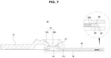
- FIG. 7 is a cross-sectional view of a test unit of the cartridge of FIG. 4 cut along AA'.
- FIGS. 1 to 7 will be collectively described to avoid overlapping explanation. Referring to FIG.
- a specimen analysis apparatus 1 combined with a cartridge 40 includes a housing 10 that forms the exterior, and a door module 20 installed on the front of the housing 10.
- the door module 20 may include a display 21, a door 22, and a door frame 23.
- the display 21 and the door 22 may be arranged on the front of the door frame 23. As shown in FIG. 1 , the display 21 may be placed above the door 22, but it may also be located anywhere that may provide various visual information for the user.
- the door 22 may be slidingly installed, and configured to be positioned behind the display 21 when slid open.
- the display 21 may display various specimen analysis information, such as the concentration of a target material in the specimen. If the display 21 is implemented as a touch screen type, the display 21 may receive various information and commands from the user.
- the display 21 may display icons for input of various control commands related to the specimen analysis apparatus 1.
- the display 21 may display a user interface configured to provide not only the icons related to controlling the specimen analysis apparatus 1 but also analysis result information. This will be described in detail later.
- the door frame 23 may be equipped with an install member 32 on which the cartridge that contains various reagents may be mounted. The user may slide the door 22 open upward to mount the cartridge 40 on the install member 32, and slide the door 22 closed downward to perform analysis operation.
- a specimen is injected to the cartridge 40 and reacts with a reagent in a test unit 45.
- the cartridge 40 is inserted into the install member 32, and a pressurizing member 31 presses the cartridge 40 for the specimen in the cartridge 40 to flow into the test unit 45.
- the specimen analysis apparatus 1 may further include an output unit 11 for outputting the analysis result in printed form. Accordingly, the user may check the analysis result through the output unit 11 as well as through the display 21.
- the cartridge 40 may be inserted into the install member 32 of the specimen analysis apparatus 1.
- the install member 32 may include a seat 32c for the cartridge 40 to be seated therein, and supporters 32f for supporting the install member 32 in the specimen analysis apparatus 1.
- the supporters 32f may be formed to extend from either ends of a body 32e of the install member 32, and the seat 32c may be arranged in the central part of the body 32e.
- a slit 32d may be formed behind the seat 32c to prevent an error that might occur in measuring a test result of a specimen sample in the test unit 45.
- the install member 32 may include contacts 32a, 32b for contacting the cartridge 40, and the test unit 45 of the cartridge 40 may include depressions 45a having the form corresponding to the contacts 32a, 32b. Thus, the depressions 45a and the contacts 32a, 32b come into contact with each other. There may be two depressions 45a and two corresponding contacts 32a, 32b, without being limited thereto.
- the cartridge 40 may include a housing 41 that forms the exterior and the test unit 45 in which the specimen and the reagent are joined and make a reaction.
- the housing 41 may be implemented in a form that supports the cartridge 40 and allows the user to be able to grip the cartridge 40.
- the housing 41 may have a user-gripping part implemented in the form of a streamlined protrusion, as shown in FIGS. 2 and 3 . Accordingly, the user may grip the cartridge 40 stably.
- the housing 41 is not limited to the form shown in the drawings, and may be implemented in various shapes.
- a specimen supplier 42 may be arranged in the cartridge 40 to receive a specimen.
- the specimen supplier 42 may include a supply hole 42b through which a specimen sample flows into the test unit 45, and an auxiliary supplier 42a for assisting in supply of the specimen.
- a specimen to be tested in the specimen analysis apparatus 1 may be supplied to the specimen supplier 42.
- the specimen herein used may also be referred to as a sample, including a bio sample such as blood, tissue fluid, lymph fluid, saliva, and urine, or an environmental sample for water-purity control or soil conservation, without being limited thereto.
- a diluted or non-diluted sample may be used, without being limited thereto.
- the supply hole 42b may have a circular form as shown in FIG. 2 , but is not limited thereto.
- the supply hole 42b may have a polygonal form.
- the user may use a tool such as a pipette or a syringe to drop the specimen onto the specimen supplier 42.
- the auxiliary supplier 42a may be formed around the supply hole 43b to be slanted toward the supply hole 42b, enabling the specimen dropped around the supply hole 42b to flow down to the supply hole 42b. Specifically, if the user fails to drop the specimen directly into the supply hole 42b but drops it around the supply hole 42b, the specimen may flow into the supply hole 42b along the slope of the auxiliary supplier 42a.
- the auxiliary supplier 42a may also prevent contamination of the cartridge 40 due to a wrongly-supplied specimen. Specifically, even if the specimen fails to go directly into the supply hole 42b, the auxiliary supplier 42a around the supply hole 42b may prevent the specimen from flowing to the test unit 45 or the gripping part, thereby preventing contamination of the cartridge 40 from the specimen and preventing the specimen that might be harmful to the human body from contacting the user.
- the specimen supplier 42 includes a single supply hole 42b
- the present disclosure is not limited thereto and a plurality of supply holes 42b may be provided.
- the single cartridge 40 may perform tests on many different specimens simultaneously.
- the different specimens may be the same type but come from different sources, or may be different types and come from different sources, or may be the same type and come from the same source but may be put in different states.
- the housing 41 since it is often the case that the housing 41 comes into contact with a specimen while having a form that facilitates a particular function, the housing 41 may be formed of an easy-to-mold and chemically and biologically inactive material.
- the housing 41 may be made of any of various materials including plastic materials, such as acryl, e.g., polymethylmethacrylate (PMMA), polysiloxane, e.g., polydimethylsiloxane (PDMS), polycarbonate (PC), linear low density polyethylene (LLDPE), low density polyethylene (LDPE), medium density polyethylene (MDPE), high density polyethylene (HDPE), polyvinyl alcohol, very low density polyethylene (VLDPE), polypropylene (PP), acrylonitrile butadiene styrene (ABS), cycloolefin copolymer (COC), etc., glass, mica, silica, semiconductor wafer, etc.
- plastic materials such as acryl, e.g., polymethylmethacrylate (PMMA), polysiloxane, e.g., polydimethylsiloxane (PDMS), polycarbonate (PC), linear low density polyethylene (LLDPE), low density polyethylene (LDPE), medium density poly
- the aforementioned materials are, however, merely examples of materials to be used for the housing 41, without being limited thereto.
- the housing 41 may be implemented with any material having chemical and biological stability and mechanical processability.
- the cartridge 40 may be configured to be combined or joined with the test unit 45.
- a specimen injected through the specimen supplier 42 may flow into the test unit 45 and may be tested as it makes a reaction with a reagent.
- the test unit 45 may include a plurality of containers 45b, each containing a reagent to react with the specimen.
- various kinds of reagents may be provided in the plurality of containers 45b.
- a reagent used to detect the concentration of a target material in the specimen may be provided in the container 45b.
- the reagent may include a coupler that shows different optical characteristics depending on concentrations of the target material in the specimen, so the specimen analysis apparatus 1 may detect an optical characteristic through a photo detector and calculate a concentration of the target material based on the detection result. This will be described in detail later.
- the target material refers to a material to be analyzed in the specimen.
- the target material may be protein, enzyme, or ion included in the specimen, without being limited thereto.
- the target material may be one of various materials that exist in the blood, such as sodium (Na), potassium (K), etc., without being limited thereto. This will be described in detail later, and in the following description, a structure of the test unit 45 of the cartridge 40 will be described in detail.
- the test unit 45 of the cartridge 40 may have a structure in which three plates 46, 47, 48 are joined.
- the three plates 46, 47, 48 may be divided into a top plate 46, a middle plate 47, and a bottom plate 48.
- the top and bottom plates 46 and 48 may be printed with light shielding ink to protect the specimen sample moving into the container 45b against light or prevent an error that might occur in measuring the optical characteristic in the container 45b.
- the top and bottom plates 46 and 48 may each be about 10 to 300 ⁇ m thick.
- the middle plate 47 may have the thickness of about 50 to 300 ⁇ m.
- the top and bottom plates 46 and 48 of the test unit 45 may be formed of a film selected from among polyethylene films, such as VLDPE, LLDPE, LDPE, MDPE, HDPE, etc., PP films, PVC films, PVA films, polystyrene (PS) films, and PET films.
- the films are merely examples, and there are no limitations on the films used to form the top and bottom plates 46 and 48 as long as the films are chemically and biologically inactive and mechanically processable.
- the middle plate 47 of the test unit 45 may be formed of a porous sheet.
- the porous sheet to be used for the middle plate 47 may include one or more of cellulose acetate, nylons (e.g., nylon 6.6, nylon 6.10), and polyether sulfone. Since the middle plate 47 is formed of a porous sheet, it serves as a vent by itself, allowing the specimen to move inside the test unit 45 without the need for an extra driving source. Furthermore, if the specimen has a hydrophile property, the middle plate 47 may be coated with a hydrophobic solution to prevent the specimen sample from permeating the middle plate 47.
- An inlet 46a through which a specimen flows in, may be formed in the top plate 46, and an area 46b corresponding to the containers 45b may be transparent. In the bottom plate 48, an area 48a corresponding to the containers 45b may also be transparent. This is to measure the absorbance, an example of optical characteristic from a reaction that occurs in the containers 45b.
- the absorbance is also referred to as reflection or transmission density, but for convenience of explanation, the former term will be used herein.
- the middle plate 47 may also have an inlet 47a for a specimen to flow in therethrough, and the inlet 46a of the top plate 46 and the inlet 47a of the middle plate 47 overlap to form an inlet 44 of the test unit 45 (see FIG. 7 ). Furthermore, the middle plate 47 may have an area 47b corresponding to the containers 45b and a fluid path 47c to connect the inlet 47a and the container 45b.
- test unit 45 for analysis of the specimen.
- a reagent that comes in a color or changes colors according to a reaction with a particular ingredient of the blood may be provided in the container 45b to optically detect and evaluate the color appearing in the container 45b. Based on the evaluations, whether there exists the particular ingredient in the blood, a ratio of the particular ingredient, the concentration, or the like may be determined.
- the cartridge 40 may be formed in such a manner that the test unit 45 is joined to the bottom of the housing 41. Specifically, the test unit 45 may be joined to the bottom of the specimen supplier 42 through the supply hole 42b formed thereon.
- a pressure sensitive adhesive may be used to join the housing and the test unit 45 together, and the PSA has properties of being adhered to an object in short period of time with low pressure, such as finger pressure, at a room temperature, preventing cohesive failure, and leaving no residuum on the surface of the object.
- the housing 41 and the test unit 45 are joined not only by the PSA but may also be joined by a double-sided adhesive or in a method of being inserted into a groove.
- the specimen flowing in through the supply hole 42b passes a filtering unit 43 and then flows into the test unit 45.
- the filtering unit 43 may be put into the supply hole 42b of the housing 41.
- the filtering unit 43 may include at least one porous membrane with many pores to filter materials included in the specimen sample, which are bigger than a predetermined size.
- the filtering unit 43 may include two-layered filters, i.e., a first or upper filter and a second or lower filter.
- the first filter may be formed of glass fiber, non-woven fabric, absorbent filter, etc.
- the second filter may be formed of PC, PES, PE, polyacrylic sulfone (PASF), etc.
- the second filter may filter the specimen again, which has already passed through the first filter. Furthermore, it may protect the filtering unit 43 from being torn or damaged in case that a lot of particles of a size greater than the pore of the filtering unit 43 flow in.
- the filtering unit 43 is not, however, limited thereto, and may be implemented in a structure of three or more layers, or a single layer. In the case of three or more layers, filtering performance of the filtering unit 43 on the specimen may be further enhanced and the stability may be improved as well.
- the filtering unit 43 may be processed with adhesive materials such as double-sided adhesives.
- the test unit 45 may include an inlet 44 through which the specimen that has passed the filtering unit 43 flows in, the fluid path 47c along which the specimen flowing in is moved, and the containers 45b in which a reaction occurs between the specimen and a reagent.
- the top, middle, and bottom plates 46, 47, and 48 may be joined together by double-sided adhesives. Specifically, a double-sided tape 49 is attached to the top and bottom faces of the middle plate 47, making the top, middle, and bottom plates 46, 47, and 48 combined together.
- the containers 45b of the cartridge 40 may be separated from another.
- the containers 45b may include a first container 50a, a second container 50b, and a third container 50c, but the number of the containers is not limited thereto.
- the first and second containers may be called sub-containers if there is no need to distinguish one from another, and the sub-containers are collectively called a container.
- the first, second, and third containers 50a, 50b, and 50c may contain different reagents to react with a target material with different concentrations of internal standard material.
- the specimen analysis apparatus 1 may produce various results by analyzing the specimen flowing into the container 45b using an optical detector 100. The respective elements of the specimen analysis apparatus 1 will now be examined.
- FIG. 8 is a block diagram of a specimen analysis apparatus
- FIG. 9 is a diagram for explaining detection of optical characteristics of a target material provided in a container.
- FIG. 10A shows how to set an optical signal value of a target material in a coordinate system
- FIG. 10B shows how to generate a plot based on coordinates set based on optical signal values of a target material.
- FIGS. 11A and 11B are graphs representing changes in concentration of a target material
- FIG. 12 shows determination of a correction value by sectionalizing a plot
- FIG. 13 shows determination of a correction value by sectionalizing a plot of change in concentration of a target material
- FIGS. 14A and 14B show a predetermined measurement range.
- FIG. 14A and 14B show a predetermined measurement range.
- FIG. 15 shows a user interface screen displayed on a display, which is configured to provide a corrected concentration of a target material
- FIG. 16 shows a user interface screen displayed on a display, which is configured to provide a corrected concentration of a target material and a plot of the corrected concentration of the target material.
- FIGS. 8 to 16 will be collectively described to avoid overlapping explanation.
- the specimen analysis apparatus 1 may include an optical detector 100 for detecting optical characteristics from a reaction between a specimen and a reagent provided in the container 45b, a memory 110 for storing control data, programs, or the like required to control overall operation of the specimen analysis apparatus 1, a controller 120 for controlling general operation of the specimen analysis apparatus 1, an output unit 11 for outputting a result of analyzing the specimen, and a display 21 for visually providing various information.
- the output unit 11 and the display 21 were described above, so the description thereof will be omitted.
- the optical detector 100 may detect optical characteristics, and the controller 120 may calculate many different analysis values to be used in diagnosis of a target subject, such as concentrations of a target material based on the detection results, as will be described below.
- the optical detector 100 may include an emitter 101 for emitting light, and a photo detector 105 for detecting light.
- the emitter 101 may be implemented with various types of well-known sensors and devices that emit light, such as a light emitting diode (LED) sensor, an infrared sensor, or the like, without being limited thereto.
- LED light emitting diode
- the photo detector 105 may collect or detect light in the container 45b.
- the photo detector 105 may be implemented by a photo diode that detects light in the container 45b and converts the light into electric energy, but is not limited thereto.
- the emitter 101 and the photo detector 105 may be arranged to face each other with the container 45b centered between them. Accordingly, the photo detector 105 may detect an optical characteristic from a reaction between a reagent and a specimen in the container 45b.
- a reagent P may be provided in the container 45b in advance.
- the reagent P is in a dried solid state and applied on one or more sides of the container 45b.
- the emitter 101 may be located adjacent to an area 46b formed in the top plate 46 to emit light to the container 45b, as shown in FIG. 9 .
- a transparent plate 102 may be attached to a side of the emitter 101, without being limited thereto.
- the photo detector 105 may be arranged adjacent to an area 48a formed in the bottom plate 48 to detect or collect light emitted by the emitter 101 to the container 45b.
- a transparent plate 106 may also be attached to a side of the photo detector 105 to prevent contamination thereof from the reagent, specimen, etc., without being limited thereto.
- Positions of the emitter 101 and photo detector 105 are not limited to what are shown in the drawings.
- the emitter 101 may be arranged at a location adjacent to the area 48a formed in the bottom plate 48 and the photo detector 105 may be arranged at a location adjacent to the area 46b formed in the top plate 46.
- the magnitude of electric energy output from the photo detector 105 may vary depending on the concentration of the target material.
- the controller 120 may calculate the absorbance, concentration, etc., based on the electric energy output from the photo detector 105.
- a reagent may be provided in advance to at least one sub-container, as described above.
- the reagent is used to measure the concentration of a target material and provided in the container 45b in a dried solid state.
- the reagent contacts the specimen, mingling with the specimen while changing into a liquid.
- the reagent may include various materials to measure a target material present in the specimen.
- the reagent may include a coupler having different optical characteristics depending on the concentration of the target material in the specimen.
- the reagent may include a material to keep the PH at the proper level in order to detect an optical characteristic of the specimen more correctly. If the PH of the specimen is out of a particular range, it makes it difficult to measure the absorbance, so the reagent may include the material to buffer the PH of the specimen.
- the reagent may include a material having an ion-selective property that attracts a particular ion. By attracting the target material using the material, the concentration of the target material may be measured more correctly.
- the reagent may include an internal standard material.
- the internal standard material is a material that contains the target material and releases the target material while being dissolved during a process of mixing with the specimen.
- sodium (Na) corresponds to the target material
- sodium chloride (NaCl) may be selected as the internal standard material.
- the internal standard material may be dissolved into ions Na+, Cl- while changing from solid to liquid as it is mixed with the specimen.
- the internal standard material may change the concentration of the target material in the container 45b as it is dissolved.
- the containers may contain the same or different reagents. Accordingly, the user may easily obtain the concentration of the target material to be measured by selecting a cartridge 40 containing a reagent related to the target material and installing the cartridge 40 in the frame 32.
- Concentrations of the internal standard material included in the reagents provided in the respective sub-containers may be set equally or differently. For example, at least one of the sub-containers may contain a reagent that does not include the internal standard material, i.e., zero concentration of internal standard material.
- a reagent including a predetermined concentration of internal standard material may be injected to at least another one of the sub-containers.
- concentration, absorbance, luminance, and fluorescence of the measured target material may be the same or different for each sub-container.
- values that may be derived using optical characteristics of the specimen such as concentration, absorbance, fluorescence, luminance of the target material are collectively called optical signal vales of the target material, and the same is true in the case that there is no need to distinguish the concentration, absorbance, fluorescence, luminance of the target material.
- Concentrations of the internal standard material injected to the respective sub-containers may be set in advance.
- the cartridge 40 may be manufactured with predetermined reagents provided in the respective sub-containers, and information about the injected reagents may be mapped to the identification information attached to the cartridge 40.
- the identification information is provided to identify the cartridge 40, such as QR code, bar code, etc., and may be mapped and stored with information about a property of the reagent injected to the container 45b.
- the information about the property of the reagent may include information about an extent of change in concentration of the target material according to an extent of change in optical signal value of the target material.
- the information about the property of the reagent may include information regarding the concentration of the injected internal standard material and the concentration of the target material that comes out as a reaction is made with the specimen.
- the information about the property of the reagent may include a calibration curve derived based on measurements in an ideal state.
- the calibration curve stored in the information about the property of the reagent may be called a factory calibration curve.
- the controller 120 may determine a correction value by comparing the factory calibration curve and the calibration curve derived from the container 45b.
- the specimen analysis apparatus 1 is equipped with an image sensor to recognize the identification information and determine the information about the property of the reagent. If the display 21 is implemented as a touch screen type, the user may input a bar code number to the display 21 and the specimen analysis apparatus 1 may obtain the information about the property of the reagent. The information about the property of the reagent may be stored in the memory 110 of the specimen analysis apparatus 1, without being limited thereto.
- the controller 120 may determine a difference in concentration of the target material between the sub-containers from the identification information, and calculate an extent of change in the optical signal value of the target material between the sub-containers from a detection result of the optical detector 100.
- the extent of change in the optical signal value of the target material between the sub-containers may include at least one of an extent of change in absorbance, an extent of change in fluorescence, and an extent of change in luminance of the target material between the sub-containers.
- the controller 120 may calculate the extent of change in the optical signal value based on the difference in concentration of the target material, and determine a correction value for a concentration of the target material by comparing the difference in concentration of the target material mapped to the identification information with the extent of change in the optical signal value.
- the controller 120 will be described in more detail later.
- the reagent includes a chromophore that shows different optical characteristics depending on the amount of a particular ingredient in the specimen, but the chromophore may change in property due to light, oxygen, moisture, etc., and thus has a problem that the measurement accuracy may decrease as time passes. Furthermore, with the lapse of time, it suffers from not only a change of the reagent itself but also a decrease in measurement accuracy if there is an interfering substance that interferes with a reaction between the reagent and the target material in the container.
- the specimen analysis apparatus 1 may compensate for or correct an optical signal value of the target material by determining a correction value for the optical signal value based on comparison of an extent of change in optical signal value between at least two containers with a predetermined extent of change, e.g., a calibration curve mapped to the identification information and derived in a normal state.
- a predetermined extent of change e.g., a calibration curve mapped to the identification information and derived in a normal state.
- the specimen analysis apparatus 1 may increase the term of validity of the cartridge, i.e., an effective life of the reagent, and diagnose a subject more correctly. This will be described in detail later, and a control block diagram of the specimen analysis apparatus 1 will now be described.
- the memory 110 of the specimen analysis apparatus 1 may be implemented in at least one of flash memory type, hard disk type, multimedia card micro type, card type (e.g., SD or XD memory), Random Access Memory (RAM), Static Random Access Memory (SRAM), Read-Only Memory (ROM), Electrically Erasable Programmable Read-Only Memory (EEPROM), Programmable Read-Only Memory (PROM), magnetic memory, magnetic disk, and optical disk.
- the memory 110 is not, however, limited thereto, and may be implemented in any type well-known in the art.
- the memory 110 may store control data, control programs, etc., used to control general operation of the specimen analysis apparatus 1. Accordingly, the controller 120 may control general operation of the specimen analysis apparatus 1 using the data stored in the memory 110.
- the memory 110 may also store instructions for executing a method for correcting the optical signal value of a target material.
- the instructions may be stored in the memory 110 in the form of a program. Accordingly, the controller 120 may perform a correction process for the optical signal value using the data stored in the memory 110, as will be described below.
- the memory 110 may also store data related to the information about the property of the reagent.
- the data related to the information about the property of the reagent is not only stored in the memory 110 but also mapped to and stored in the identification information provided on the cartridge 40 as described above.
- the capacity of the memory 120 may be more efficiently managed. Furthermore, if the information about the property of the reagent needs to be updated or replaced, the update or replacement may be easily performed because only the identification information needs to be replaced without the need to update the memory 120.
- the memory 110 may also store data about a user interface.
- the user interface refers to an environment configured to allow the user to easily input various setting instructions or control command for the specimen analysis apparatus 1, easily control the program stored in the memory 110, and easily obtain various information such as analysis results from the specimen analysis apparatus 1.
- the user interface may be a graphic user interface (GUI) that graphically implements screens to be displayed on the display 21 in order to more conveniently perform exchange of various information between the user and the specimen analysis apparatus 1.
- GUI graphic user interface
- Methods for providing various information and displaying and arranging icons to receive various setting instructions and control commands may be implemented in an algorithm or program and stored in the memory 110. Accordingly, the controller 120 may generate a user interface using the data stored in the memory 110 and display the user interface on the display 21. Alternatively, the algorithm or program may be stored in an external device. In this case, the controller 120 may receive data related to the user interface derived from the algorithm or program over a communication network and display the user interface on the display 21, without being limited thereto.
- the data stored in the memory 110 may be updated.
- the user interface, the method for compensating for the optical signal value of the target material, or the data related to the information about the property of the reagent stored in the memory 110 may be updated over a wired or wireless communication network, without being limited thereto.
- the data stored in the memory 110 may be updated according to a control command of the user or automatically updated at predetermined intervals, without being limited thereto.
- the memory 110 and the controller 120 may be implemented separately or integrated in a system on chip (SOC) embedded in the specimen analysis apparatus 1, without being limited thereto.
- SOC system on chip
- the controller 120 may be equipped in the specimen analysis apparatus 1.
- the controller 120 may be implemented by a device that is capable of processing various operations, such as a processor.
- the controller 120 may control overall operation of the elements of the specimen analysis apparatus 1 with control signals.
- the controller 120 may send a control signal to control the output unit 11 to output the analysis result.
- the controller 120 may send a control signal to display the analysis result of the specimen on the display 21.
- the controller 120 may analyze the target material in the specimen based on the optical characteristics of the specimen detected by the optical detector 100. A method for determining a correction value for a concentration of the target material, which is performed by the controller 120, will now be described in detail.
- the controller 120 may determine a concentration of the target material based on the absorbance. For example, as the concentration of the target material increases, the absorbance may increase or decrease depending on the reagent. The controller 120 may use the data stored in the memory 110 to derive a concentration of the target material from the absorbance in the container 45b.
- the controller 120 may calculate concentrations of the target material in at least two sub-containers in order to determine a correction value for a concentration of the target material.
- a reagent with no internal standard material may be provided in the first container, and a reagent with the internal standard material of concentration ⁇ may be provided in the second container.
- Information regarding concentrations of the internal standard material provided in the respective sub-containers may be stored in the memory 110 or mapped to and stored in the identification information provided on the cartridge 40.
- the controller 120 may determine optical signal values of the target material in the first and second containers. For example, the controller 120 may determine not only the absorbance, fluorescence, luminance but also concentrations in the respective first and second containers.
- the controller 120 may then set the absorbance and concentration in a two dimensional (2D) coordinate system, as shown in FIG. 10A .
- the x-axis represents the concentration of the target material
- the y-axis represents the absorbance of the target material.
- the y-axis is not limited to the absorbance of the target material but may represent the fluorescence or luminance of the target material, without being limited thereto.
- the absorbance of the target material in the first and second containers correspond respectively to c and d.
- the controller 120 may then calculate concentration S of the target material in the first container based on the absorbance.
- Information about the concentration ⁇ of the target material that increases due to the internal standard material provided in the second container in advance may be mapped to the identification information or stored in the memory 110. Accordingly, the controller 120 may calculate the concentration of the target material in the second container from the absorbance d, but also calculate the concentration S+ ⁇ of the target material in the second container from the information stored in the identification information or the memory 110.
- the controller 120 may use the concentration ⁇ determined from the memory 110 or the identification information to calculate the concentration of the target material in the second container, thereby more accurately determining a difference in concentration of the target material between the first and second containers.
- the coordinates of the optical signal value of the first container may be set to (S, c), and the coordinates of the optical signal value of the second container may be set to (S+ ⁇ , d).
- the coordinates of the optical signal values of the first and second containers are referred to as first and second coordinates, respectively.
- the absorbance c may be less than the absorbance d as shown in FIG. 10A , but alternatively, the absorbance c may be greater than the absorbance d .
- the target material may come in brighter color or darker color according to a reaction with the reagent, without being limited thereto.
- the controller 120 may determine an extent of change in the optical signal value using the coordinates set in the graph. For example, the controller 120 may generate a straight line that connects the first coordinates (S, c) and the second coordinates (S+ ⁇ , d) as shown in FIG. 10B , and calculate a slope a of the straight line.
- the slope a refers to an inclination derived based on the extent of change in the optical signal value derived from the reaction between the specimen and the reagent in the container.
- the information about the property of the reagent may include information relating to a concentration graph depending on the absorbance, as shown in FIGS. 11A and 11B .
- the specimen analysis apparatus 1 may compare the optical signal value derived in the container 45b with the optical signal value derived in an ideal state to compensate for or correct the optical signal value derived in the container 45b, thereby increasing the term of validity of the cartridge 40.
- the change of concentration depending on the absorbance in may be constant with the slope b a certain range.
- the slope b1 representing the change of concentration depending on the absorbance may not be constant.
- the slopes b and b1 are derived based on the stored data, e.g., the information about the property of the reagent, and correspond to slopes derived based on the extent of change in the optical signal value according to the difference between the internal standard materials in an ideal state.
- the controller 120 may correct the optical signal value of the target material, thereby increasing the term of validity of the cartridge 40.
- the controller 120 may determine a correction value using various methods.
- the container includes a plurality of sub-containers, e.g., three sub-containers
- a specimen is injected to the first, second, and third containers and may react with the reagents.
- the concentration of the internal standards material provided in advance in the third container may be higher than those in the first and second containers.
- the concentration of the target material that increases due to the internal standard material injected to the third container may be ⁇ ( ⁇ > ⁇ ).
- a slope between the first and second containers i.e., a slope between the specimen concentrations S and S+ ⁇
- the slope between the second and third containers i.e., the slope between the specimen concentrations S+ ⁇ and S+ ⁇ .
- the slopes a2 and a3 may or may not be the same.
- the controller 120 may calculate the slope b2 of a region between the specimen concentrations S and S+ ⁇ and the slope b3 of a region between the specimen concentrations S+ ⁇ and S+ ⁇ based on the information about the property of the reagent, as shown in FIG. 13 .
- the slope b2 of the region between the specimen concentrations S and S+ ⁇ may be an average slope of the region or a slope at the specimen concentration S.
- the slope b3 of the region between the specimen concentrations S+ ⁇ and S+ ⁇ may also be an average slope of the region, or a slope at the specimen concentration S+ ⁇ , without being limited thereto.
- the controller may determine a correction value for each region, and use the correction value to calculate a corrected concentration of the target material for the region. Accordingly, the controller 120 may provide the trend of changes in the optical signal value, which are expected more accurately, i.e., a graph representing changes of the optical signal value, thereby making more accurate diagnosis on the target subject.
- the controller 120 may use the optical signal values in all the sub-containers to correct the trend of changes in the target material, or use only the optical signal values in a particular range to correct the trend of changes in the target material.
- the controller 120 may use only the optical signal values in a predetermined measurement range, e.g., in a dynamic range of the optical detector 100 to correct the trend of changes of the target material.
- the controller 120 may determine whether the optical signal values derived from the plurality of the sub-containers are in a reliable range, and based on the determination result, may select an optical signal value to be used in correcting a concentration. In other words, the controller 120 may not use all the optical signal values derived from all the sub-containers but select one of the sub-containers, in which an optical signal value is derived from the set measurement range, and use the optical signal value in the selected sub-container, thereby leaving out optical signal values with significant errors.
- a normal measurement range may be set in advance using at least one of the optical signal values.
- a first measurement range DR1 set in advance may be set to a particular concentration range, as shown in FIG. 14A .
- the controller 120 may not use the optical signal value for the third container for correction, which is out of the first measurement range DR1.
- a second measurement range DR2 set in advance may be set to a particular absorbance range, as shown in FIG. 14B .
- the controller 120 may not use the optical signal value for the third container for correction, which is out of the second measurement range DR.
- the controller 120 may display a user interface on the display 21, which is implemented to include at least one of icons that may receive various control instructions, the corrected concentration of the target material, and plots of changes in the corrected concentration of the target material.
- the user interface refers to an environment in which the user may be able to control the elements and program of the specimen analysis apparatus 1 and obtain the various information more easily.
- the user interface as herein used may be a GUI that graphically implements screens to be displayed on the display 21 in order to more conveniently perform exchange of various information between the user and the specimen analysis apparatus 1.
- the GUI may be implemented to display icons or buttons in some area on the screen displayed on the display 21 to receive various control instructions from the user more easily, and display at least one widget or pop-up message in some other area to display various information.
- FIG. 15 shows a user interface screen displayed on a display, which is configured to provide a corrected concentration of a target material
- FIG. 16 shows a user interface screen displayed on a display, which is configured to provide a corrected concentration of a target material and a plot of the corrected concentration of the target material.
- the user interface may be configured to include a pop-up message 1420 saying contents of a cartridge number, Q01 and a corrected concentration of the target material, K:8.5.
- the user interface may include an icon 1410 to go back to the main screen.
- the controller 120 may display a user interface on the display 21, which is configured to provide not only a corrected concentration of the target material but also a pop-up message 1430 having a plot of changes of the corrected concentration of the target material, as shown in FIG. 16 . Operation flows of the specimen analysis apparatus 1 will now be briefly described.
- FIG. 17 is a flowchart illustrating operation of a specimen analysis apparatus for determining a correction value for a concentration of a target material.
- a cartridge may be inserted into a specimen analysis apparatus.
- the specimen analysis apparatus 1 may include the door frame 23 (see FIG. 1 ) equipped with the install member 32 (see FIG. 2 ) on which the cartridge 40 (also see FIG. 2 ) for containing various reagents may be mounted, allowing the cartridge 40 to be mounted on the install member 32 by insertion.
- At least two containers formed in the cartridge 40 may contain reagents in advance, which include an internal standard material with predetermined concentrations.
- a specimen may be injected into the at least two containers having the internal standard material with different concentrations through the specimen supplier 42 (see FIG. 2 ) of the cartridge 40, in operation 1700.
- the specimen injected through the specimen supplier 42 may flow into the container 45b along the fluid path 47c (see FIG. 7 ) and make a reaction with the reagent.
- the specimen injection apparatus 1 may detect optical characteristics from the reaction between the specimen and the reagent in the container with the optical detector.
- the specimen analysis apparatus may use the optical detector to measure the absorbance of the target material in the at least two containers, in operation 1710. Since the at least two containers contain the internal standard material with different concentrations, concentrations of the target material in the at least two containers may be different and the measured absorbance may also be different.
- the specimen analysis apparatus may then determine an extent of change in the absorbance according to the difference of concentrations of the target material between the containers.
- the difference of concentrations of the target material between the containers may also be derived from the absorbance, or from the identification information provided on the cartridge 40 or the information about the property of the reagent stored in the memory.
- the specimen analysis apparatus 1 may determine a correction value for a concentration of the target material by comparing the extent of change in absorbance according to the difference of concentrations of the target material between the containers with the extent of change in absorbance based on the difference of concentrations derived from the identification information attached to the cartridge 40 or the information about the property of the reagent stored in the memory, in operation 1720.
- the extent of change in absorbance according to the difference of concentrations of the target material between containers is called a measured calibration curve, and the extent of change in absorbance based on the difference of concentrations derived from the identification information provided on the cartridge 40 or the information about the property of the reagent stored in the memory is called a factory calibration curve.
- reagents may be injected to a plurality of containers. In this regard, it is more likely that the reagent fails to normally react with the specimen as the description may change with the passing of time.
- the reagent fails to make a normal reaction with the specimen, if the provided reagent does not reach a fixed quantity, or if an interfering material is provided in the container in the process of manufacturing the cartridge.
- the specimen analysis apparatus may enable more accurate diagnosis of the subject as well as increase a period of usage of the cartridge, by comparing the measured calibration curve with the factory calibration curve to correct the optical signal value of a target material. Operation flows of the specimen analysis apparatus for correcting the optical signal value of a target material using a reliable optical signal value will now be descried briefly.
- FIG. 18 is a flowchart illustrating operation of a specimen analysis apparatus for determining a correction value by selecting an optical signal value from within a normal measurement range.
- the specimen analysis apparatus calculates optical signal values of the target material in at least two containers having an internal standard material injected with different concentrations, in operation 1800.
- the optical signal value of the target material may include at least one of concentration, luminance, fluorescence, and absorbance of the target material. Details of how to calculate the optical signal value of the target material were described above, so the description will now be omitted.
- the specimen analysis apparatus determines whether the optical signal value of the target material is within a set measurement range, in operation 1810.
- the set measurement range refers to a range used to determine whether the optical signal value of the target material is in a reliable range.
- the set measurement range may be stored in the memory of the specimen analysis apparatus, or may be mapped to and stored in the identification information.
- the set measurement range may be set based on concentration values or absorbance, as described above, without being limited thereto.
- the specimen analysis apparatus may enable more accurate diagnosis of the subject by correcting a concentration of the target material using a reliable optical signal value.
- the specimen analysis apparatus determines whether the optical signal value of the target material is within the set measurement range, and based on the determination, selects an optical signal value to be used in determining a correction value, in operation 1820. For example, referring to FIG. 14B , the specimen analysis apparatus may leave out optical signal values for the third container, which are out of the set second measurement range DR2 in determining the correction value.
- the specimen analysis apparatus determines a correction value for a concentration of the target material using the selected at least one optical signal value, in operation 1830.
- the specimen analysis apparatus may generate a measured calibration curve using the optical signal values in the container, and determine a correction value by comparing the measured calibration curve and the factory calibration curve. This was described above, so the detailed description thereof will be omitted.
- the specimen analysis apparatus may increase the terms of validity of the cartridge, and increase reliability of the product itself by enabling more accurate diagnosis of the subject.
Landscapes
- Health & Medical Sciences (AREA)
- Physics & Mathematics (AREA)
- Life Sciences & Earth Sciences (AREA)
- Engineering & Computer Science (AREA)
- Chemical & Material Sciences (AREA)
- Immunology (AREA)
- General Health & Medical Sciences (AREA)
- Biochemistry (AREA)
- General Physics & Mathematics (AREA)
- Analytical Chemistry (AREA)
- Pathology (AREA)
- Spectroscopy & Molecular Physics (AREA)
- Biomedical Technology (AREA)
- Molecular Biology (AREA)
- Urology & Nephrology (AREA)
- Hematology (AREA)
- Food Science & Technology (AREA)
- Medicinal Chemistry (AREA)
- Biophysics (AREA)
- Bioinformatics & Computational Biology (AREA)
- Biotechnology (AREA)
- Cell Biology (AREA)
- Microbiology (AREA)
- Bioinformatics & Cheminformatics (AREA)
- Chemical Kinetics & Catalysis (AREA)
- Mathematical Physics (AREA)
- Theoretical Computer Science (AREA)
- Plasma & Fusion (AREA)
- Toxicology (AREA)
- Quality & Reliability (AREA)
- Dispersion Chemistry (AREA)
- Proteomics, Peptides & Aminoacids (AREA)
- Tropical Medicine & Parasitology (AREA)
- Investigating Or Analysing Materials By The Use Of Chemical Reactions (AREA)
- Investigating, Analyzing Materials By Fluorescence Or Luminescence (AREA)
Claims (15)
- Probenanalyseeinrichtung (1) zum Bestimmen einer Konzentration eines Zielmaterials in einer Probe, umfassend:eine Kartusche (40), die mindestens zwei Behälter (45b) umfasst, wobei jeder Behälter (45b) ein Reagenz enthält, das so konfiguriert ist, dass es mit dem Zielmaterial in der Probe reagiert, um die Konzentration des Zielmaterials zu messen, wobei jedes Reagenz weiter eine vorbestimmte Konzentration an internem Standardmaterial beinhaltet, das das Zielmaterial enthält, wobei das interne Standardmaterial so konfiguriert ist, dass es das Zielmaterial freisetzt, während es während eines Prozesses des Mischens mit der Probe aufgelöst wird, und wobei sich die Konzentrationen der internen Standardmaterialien in den Reagenzien der mindestens zwei Behälter (45b) unterscheiden;eine optische Detektoreinheit (100) zum Detektieren von optischen Merkmalen anhand einer Reaktion zwischen dem Zielmaterial in der Probe und dem freigesetzten Zielmaterial in den internen Standardmaterialien mit den Reagenzien in den mindestens zwei Behältern (45b), und Bereitstellen von optischen Signalwerten;eine Steuerung (120), die so konfiguriert ist, dass sie:eine gemessene Kalibrierungskurve anhand eines Ausmaßes einer Änderung des optischen Signalwerts des Zielmaterials, der in den mindestens zwei Behältern (45b) gemessen wird, ableitet;dadurch gekennzeichnet, dass die Steuerung (120) weiter so konfiguriert ist, dass sie:anhand von Identifikationsinformationen, die auf der Kartusche bereitgestellt sind, und/oder anhand von Informationen über die Eigenschaft des Reagens, die in einem Speicher der Einrichtung gespeichert sind, eine Werkskalibrierungskurve erhält, die ein vorbestimmtes Ausmaß einer Änderung des optischen Signalwerts des Zielmaterials in den mindestens zwei Behältern angibt;auf Basis eines Vergleichs der gemessenen Kalibrierungskurve mit der Werkskalibrierungskurve einen Korrekturwert zum Berechnen der Konzentration des Zielmaterials bestimmt; undeine korrigierte Konzentration des Zielmaterials auf Basis des Korrekturwerts bestimmt.
- Probenanalyseeinrichtung (1) nach Anspruch 1,
wobei einer der mindestens zwei Behälter (45b) kein internes Standardmaterial aufweist, das ihm injiziert wird, und der andere der mindestens zwei Behälter (45b) ein internes Standardmaterial aufweist, das ihm mit einer vorbestimmten Konzentration injiziert wird. - Probenanalyseeinrichtung (1) nach Anspruch 1,
wobei das Ausmaß der Änderung des optischen Signalwerts des Zielmaterials ein Ausmaß einer Änderung mindestens eines von einem Absorptionsgrad, einer Fluoreszenz und einer Leuchtdichte gemäß einer Differenz der Konzentrationen des Zielmaterials in den mindestens zwei Behältern (45b) umfasst. - Probenanalyseeinrichtung (1) nach Anspruch 1,
wobei die Steuerung (120) so konfiguriert ist, dass sie eine Steigung einer Änderung eines Absorptionsgrades auf Basis eines Absorptionsgrades des Zielmaterials, der anhand eines der mindestens zwei Behälter (45b) gemessen wird, eines Absorptionsgrades des Zielmaterials, der anhand des anderen gemessen wird, und einer Differenz der Konzentrationen des Zielmaterials zwischen den mindestens zwei Behältern (45b) berechnet, wobei der Korrekturwert für die Konzentration des Zielmaterials unter Verwendung der berechneten Steigung der Änderung des Absorptionsgrades bestimmt wird. - Probenanalyseeinrichtung (1) nach Anspruch 1,wobei die Steuerung (120) so konfiguriert ist, dass sie auf Basis eines Absorptionsgrades des Zielmaterials, der anhand eines der mindestens zwei Behälter (45b) gemessen wird, eines Absorptionsgrades des Zielmaterials, der anhand des anderen gemessen wird, und einer Differenz der Konzentrationen des Zielmaterials zwischen den mindestens zwei Behältern (45b) einen Betrag einer Änderung eines Absorptionsgrades berechnet, undwobei die gemessene Kalibrierungskurve und die Werkskalibrierungskurve anhand des berechneten Änderungsbetrags des Absorptionsgrades abgeleitet werden, wobei der Korrekturwert für die korrigierte Konzentration des Zielmaterials unter Verwendung des berechneten Änderungsbetrags des Absorptionsgrades auf Basis der Differenz der Konzentrationen des Zielmaterials zwischen den mindestens zwei Behältern bestimmt wird.
- Probenanalyseeinrichtung (1) nach Anspruch 1,
wobei die Steuerung (120) so konfiguriert ist, dass sie eine Steigung einer Änderung einer Leuchtdichte auf Basis einer Leuchtdichte des Zielmaterials, die anhand eines der mindestens zwei Behälter (45b) gemessen wird, einer Leuchtdichte des Zielmaterials, die anhand des anderen gemessen wird, und einer Differenz der Konzentrationen des Zielmaterials zwischen den mindestens zwei Behältern (45b) berechnet, wobei der Korrekturwert für die korrigierte Konzentration des Zielmaterials unter Verwendung der berechneten Steigung der Änderung der Leuchtdichte bestimmt wird. - Probenanalyseeinrichtung (1) nach Anspruch 1,
wobei die Steuerung (120) so konfiguriert ist, dass sie eine Steigung der Änderung einer Fluoreszenz auf Basis einer Fluoreszenz des Zielmaterials, die anhand eines der mindestens zwei Behälter (45b) gemessen wird, einer Fluoreszenz des Zielmaterials, die anhand des anderen gemessen wird, und einer Differenz der Konzentrationen des Zielmaterials zwischen den mindestens zwei Behältern (45b) berechnet, wobei der Korrekturwert für die korrigierte Konzentration des Zielmaterials unter Verwendung der berechneten Steigung der Änderung der Fluoreszenz bestimmt wird. - Probenanalyseeinrichtung (1) nach Anspruch 1,
wobei die Steuerung (120) so konfiguriert ist, dass sie mindestens einen Bereich zwischen mindestens zwei Probenkonzentrationen in der gemessenen Kalibrierungskurve, der einer Differenz der Konzentrationen des Zielmaterials zwischen den mindestens zwei Behältern (45b) entspricht, und ein Ausmaß einer Änderung des optischen Signalwerts des Zielmaterials für jeden Bereich bestimmt, und das Ausmaß der Änderung des optischen Signalwerts des Zielmaterials für jeden Bereich mit der Werkskalibrierungskurve vergleicht, die anhand des vorbestimmten Ausmaßes einer Änderung des optischen Signalwerts des Zielmaterials für den Bereich abgeleitet wird, um einen Korrekturwert für eine Konzentration des Zielmaterials für jeden Bereich zu bestimmen. - Probenanalyseeinrichtung (1) nach Anspruch 1, die mindestens eines der folgenden Merkmale umfasst:die Steuerung (120) ist so konfiguriert, dass sie anhand eines Absorptionsgrades des Zielmaterials auf Basis des Korrekturwerts für eine Konzentration des Zielmaterials eine Darstellung von Konzentrationsänderungen erzeugt,ein vorbestimmtes Ausmaß der Änderung des optischen Signalwerts des Zielmaterials ist in einem Speicher (110) gespeichert oder Identifikationsinformationen, die an der Kartusche (40) angebracht sind, zugeordnet und in diesen gespeichert, unddie Steuerung (120) ist so konfiguriert, dass sie bestimmt, ob optische Signalwerte des Zielmaterials, die anhand der mindestens zwei Behälter (45b) gemessen werden, innerhalb eines vorbestimmten Messbereichs liegen, und auf Basis der Bestimmung bestimmt, ob die optischen Signalwerte beim Bestimmen des Korrekturwerts für die Konzentration des Zielmaterials verwendet werden sollen.
- Messverfahren zum Bestimmen einer Konzentration eines Zielmaterials in einer Probe, wobei das Verfahren umfasst:Empfangen der Probe in mindestens zwei Behältern (45b), wobei jeder Behälter (45b) ein Reagenz enthält, das so konfiguriert ist, dass es mit dem Zielmaterial in der Probe reagiert, um die Konzentration des Zielmaterials zu messen, wobei jedes Reagenz weiter eine vorbestimmte Konzentration an internem Standardmaterial beinhaltet, das das Zielmaterial enthält, wobei das interne Standardmaterial so konfiguriert ist, dass es das Zielmaterial freisetzt, während es während eines Prozesses des Mischens mit der Probe aufgelöst wird, und wobei sich die Konzentrationen der internen Standardmaterialien in den Reagenzien der mindestens zwei Behälter (45b) unterscheiden;Detektieren von optischen Merkmalen anhand einer Reaktion zwischen dem Zielmaterial in der Probe und den internen Standardmaterialien mit den Reagenzien in den mindestens zwei Behältern (45b), und Bereitstellen von optischen Signalwerten;Ableiten einer gemessenen Kalibrierungskurve anhand eines Ausmaßes einer Änderung des optischen Signalwerts des Zielmaterials, der in den mindestens zwei Behältern (45b) gemessen wird;dadurch gekennzeichnet, dass das Verfahren weiter umfasst:Erhalten, anhand von Identifikationsinformationen, die auf der Kartusche bereitgestellt sind, und/oder anhand von Informationen über die Eigenschaft des Reagens, die in einem Speicher der Einrichtung gespeichert sind, einer Werkskalibrierungskurve, die ein vorbestimmtes Ausmaß einer Änderung des optischen Signalwerts des Zielmaterials in den mindestens zwei Behältern angibt;Bestimmen, auf Basis eines Vergleichs der gemessenen Kalibrierungskurve mit der Werkskalibrierungskurve, eines Korrekturwerts zum Berechnen der Konzentration des Zielmaterials; undBestimmen einer korrigierten Konzentration des Zielmaterials auf Basis des Korrekturwerts.
- Verfahren nach Anspruch 10,
wobei das Bestimmen des Korrekturwerts für die Konzentration des Zielmaterials umfasst:
Berechnen einer Steigung der Änderung eines Absorptionsgrades auf Basis eines Absorptionsgrades des Zielmaterials, der anhand eines der mindestens zwei Behälter (45b) gemessen wird, eines Absorptionsgrades des Zielmaterials, der anhand des anderen gemessen wird, und einer Differenz der Konzentrationen des Zielmaterials zwischen den mindestens zwei Behältern (45b), wobei der Korrekturwert für die Konzentration des Zielmaterials unter Verwendung der berechneten Steigung der Änderung des Absorptionsgrades bestimmt wird. - Verfahren nach Anspruch 10,
wobei das Bestimmen des Korrekturwerts für die Konzentration des Zielmaterials umfasst:
Berechnen eines Betrags der Änderung eines Absorptionsgrades auf Basis eines Absorptionsgrades des Zielmaterials, der anhand eines der mindestens zwei Behälter (45b) gemessen wird, eines Absorptionsgrades des Zielmaterials, der anhand des anderen gemessen wird, und einer Differenz der Konzentrationen des Zielmaterials zwischen den mindestens zwei Behältern (45b), wobei der Korrekturwert für die Konzentration des Zielmaterials unter Verwendung des berechneten Änderungsbetrags des Absorptionsgrades gemäß der Differenz der Konzentrationen des Zielmaterials, und durch Vergleichen der berechneten Änderung des Absorptionsgrades mit einer vorbestimmten Änderung des Absorptionsgrades bestimmt wird. - Verfahren nach Anspruch 10,
wobei das Bestimmen des Korrekturwerts für die Konzentration des Zielmaterials umfasst:
Berechnen einer Steigung einer Änderung einer Leuchtdichte auf Basis einer Leuchtdichte des Zielmaterials, die anhand eines der mindestens zwei Behälter (45b) gemessen wird, einer Leuchtdichte des Zielmaterials, die anhand des anderen gemessen wird, und einer Differenz der Konzentrationen des Zielmaterials zwischen den mindestens zwei Behältern (45b), wobei der Korrekturwert für die Konzentration des Zielmaterials unter Verwendung der berechneten Steigung der Änderung der Leuchtdichte bestimmt wird. - Verfahren nach Anspruch 10,
wobei das Bestimmen des Korrekturwerts für die Konzentration des Zielmaterials umfasst:
Berechnen einer Steigung der Änderung einer Fluoreszenz auf Basis einer Fluoreszenz des Zielmaterials, die anhand eines der mindestens zwei Behälter (45b) gemessen wird, einer Fluoreszenz des Zielmaterials, die anhand des anderen gemessen wird, und einer Differenz der Konzentrationen des Zielmaterials zwischen den mindestens zwei Behältern (45b), wobei der Korrekturwert für die Konzentration des Zielmaterials unter Verwendung der berechneten Steigung der Änderung der Fluoreszenz bestimmt wird. - Verfahren nach Anspruch 10, das weiter die folgenden Schritte umfasst:Bestimmen mindestens eines Bereichs zwischen mindestens zwei Probenkonzentrationen in der gemessenen Kalibrierungskurve, der einer Differenz der Konzentrationen des Zielmaterials zwischen den mindestens zwei Behältern (45b) entspricht, und eines Ausmaßes einer Änderung eines optischen Signalwerts des Zielmaterials für jeden Bereich, undVergleichen des Ausmaßes der Änderung des optischen Signalwerts des Zielmaterials für jeden Bereich mit der Werkskalibrierungskurve, die anhand des vorbestimmten Ausmaßes einer Änderung des optischen Signalwerts des Zielmaterials für den Bereich abgeleitet wird, um einen Korrekturwert für eine Konzentration des Zielmaterials für jeden Bereich zu bestimmen; und/oderErzeugen einer Darstellung von Konzentrationsänderungen gemäß einem Absorptionsgrad des Zielmaterials auf Basis des bestimmten Korrekturwerts für die Konzentration des Zielmaterials; und/oderBestimmen, ob optische Signalwerte des Zielmaterials, die anhand der mindestens zwei Behälter (45b) gemessen werden, innerhalb eines vorbestimmten Messbereichs liegen, und Bestimmen, auf Basis der Bestimmung, ob die optischen Signalwerte beim Bestimmen des Korrekturwerts für die Konzentration des Zielmaterials verwendet werden sollen.
Applications Claiming Priority (1)
| Application Number | Priority Date | Filing Date | Title |
|---|---|---|---|
| KR1020160125982A KR101999260B1 (ko) | 2016-09-30 | 2016-09-30 | 검체 분석 장치 및 그 측정방법 |
Publications (2)
| Publication Number | Publication Date |
|---|---|
| EP3301432A1 EP3301432A1 (de) | 2018-04-04 |
| EP3301432B1 true EP3301432B1 (de) | 2024-08-14 |
Family
ID=59997279
Family Applications (1)
| Application Number | Title | Priority Date | Filing Date |
|---|---|---|---|
| EP17194139.6A Active EP3301432B1 (de) | 2016-09-30 | 2017-09-29 | Probenanalysevorrichtung und messverfahren dafür |
Country Status (3)
| Country | Link |
|---|---|
| US (1) | US20180095069A1 (de) |
| EP (1) | EP3301432B1 (de) |
| KR (1) | KR101999260B1 (de) |
Families Citing this family (3)
| Publication number | Priority date | Publication date | Assignee | Title |
|---|---|---|---|---|
| JP6442028B1 (ja) * | 2017-11-30 | 2018-12-19 | シスメックス株式会社 | 検体測定方法および検体測定装置 |
| KR102577993B1 (ko) * | 2018-04-06 | 2023-09-18 | 프리시젼바이오 주식회사 | 유체 검사 카트리지, 이를 포함하는 유체 검사장치 및 검사장치의 제어방법 |
| CN109974788A (zh) * | 2019-04-24 | 2019-07-05 | 西南交通大学 | 一种基于微机控制的化学实验箱 |
Citations (1)
| Publication number | Priority date | Publication date | Assignee | Title |
|---|---|---|---|---|
| US5462879A (en) * | 1993-10-14 | 1995-10-31 | Minnesota Mining And Manufacturing Company | Method of sensing with emission quenching sensors |
Family Cites Families (7)
| Publication number | Priority date | Publication date | Assignee | Title |
|---|---|---|---|---|
| JPS59157538A (ja) * | 1983-02-25 | 1984-09-06 | Hitachi Ltd | 標準添加法を適用し得る分析計 |
| GB2243211A (en) * | 1990-04-20 | 1991-10-23 | Philips Electronic Associated | Analytical instrument and method of calibrating an analytical instrument |
| DE10043113C2 (de) * | 2000-08-31 | 2002-12-19 | Pe Diagnostik Gmbh | Verfahren zur Verbesserung der Messgenauigkeit bei Sensoren, insbesondere Bio-Sensoren, die Fluoreszenzstrahlung auswerten |
| US20130203613A1 (en) * | 2009-04-09 | 2013-08-08 | Bayer Cropscience Ag | Device and method for the verification and quantitative analysis of analytes, particularly mycotoxins |
| EP2618161A1 (de) * | 2010-09-17 | 2013-07-24 | Universal Bio Research Co., Ltd. | Kartusche und automatische analysevorrichtung |
| US20150293097A1 (en) * | 2012-10-08 | 2015-10-15 | General Electric Company | Preloaded test substrates for testing lal-reactive substances, methods of use, and methods of making |
| EP2813839A1 (de) * | 2013-06-12 | 2014-12-17 | Roche Diagniostics GmbH | Kalibrierverfahren für Fotometrie |
-
2016
- 2016-09-30 KR KR1020160125982A patent/KR101999260B1/ko active Active
-
2017
- 2017-09-29 US US15/720,617 patent/US20180095069A1/en not_active Abandoned
- 2017-09-29 EP EP17194139.6A patent/EP3301432B1/de active Active
Patent Citations (1)
| Publication number | Priority date | Publication date | Assignee | Title |
|---|---|---|---|---|
| US5462879A (en) * | 1993-10-14 | 1995-10-31 | Minnesota Mining And Manufacturing Company | Method of sensing with emission quenching sensors |
Also Published As
| Publication number | Publication date |
|---|---|
| KR101999260B1 (ko) | 2019-07-12 |
| KR20180035998A (ko) | 2018-04-09 |
| EP3301432A1 (de) | 2018-04-04 |
| US20180095069A1 (en) | 2018-04-05 |
Similar Documents
| Publication | Publication Date | Title |
|---|---|---|
| US12174180B2 (en) | Fluid test cartridge, fluid test apparatus including the same, and method for controlling the fluid test apparatus | |
| CN110869745B (zh) | 用于执行光学测定的设备、系统和方法 | |
| CN105164534A (zh) | 用于生成体液样本中分析物浓度的校正值的方法/设备 | |
| CN110869746B (zh) | 利用通用电路系统执行光学和电化学测定的技术 | |
| JP7066726B2 (ja) | 流体試料中のグルコース濃度を検出するための垂直流アッセイデバイス | |
| KR20160067607A (ko) | 검사장치 및 그 제어 방법 | |
| EP3301432B1 (de) | Probenanalysevorrichtung und messverfahren dafür | |
| SE1851117A1 (en) | Sample loading cartridge for a microfluidic device | |
| US20220357347A1 (en) | Device and method to evaluate a fluid sample on a single-use multianalyte consumable | |
| KR20160081669A (ko) | 반응 장치, 검사 장치 및 검사 방법 | |
| EP3355066A1 (de) | Flüssigkeitsanalysekartusche und flüssigkeitsanalysevorrichtung damit | |
| US20180195967A1 (en) | Test instrument and method of controlling the same | |
| US20150160137A1 (en) | Inspection apparatus and inspection method using the same | |
| US20170167985A1 (en) | Specimen analysis apparatus and method of analyzing specimen using the same | |
| US20260016492A1 (en) | Point-of-care blood analysis system | |
| KR102453637B1 (ko) | 검사장치 및 검사장치의 제어방법 | |
| KR101067493B1 (ko) | 생체물질 분석을 위한 다기능성 스트립 어댑터 및 이를 이용하는 혼합형 측정기 | |
| US10118172B2 (en) | Fluid analysis cartridge and fluid analysis apparatus having the same | |
| CA3143250C (en) | System and method of measurement and calibration of analyte testing | |
| WO2026024803A1 (en) | Test consumables that maintain sample integrity for use in diagnostic sample analyzers | |
| KR102076524B1 (ko) | 유체 시료 검사장치 및 유체 시료 검사방법 | |
| CA2971389C (en) | Methods and systems for improving precision of measurements for reduced sample volumes | |
| KR20080036593A (ko) | 분석물을 검출하기 위한 가요성 장치 및 방법 |
Legal Events
| Date | Code | Title | Description |
|---|---|---|---|
| PUAI | Public reference made under article 153(3) epc to a published international application that has entered the european phase |
Free format text: ORIGINAL CODE: 0009012 |
|
| STAA | Information on the status of an ep patent application or granted ep patent |
Free format text: STATUS: REQUEST FOR EXAMINATION WAS MADE |
|
| 17P | Request for examination filed |
Effective date: 20170929 |
|
| AK | Designated contracting states |
Kind code of ref document: A1 Designated state(s): AL AT BE BG CH CY CZ DE DK EE ES FI FR GB GR HR HU IE IS IT LI LT LU LV MC MK MT NL NO PL PT RO RS SE SI SK SM TR |
|
| AX | Request for extension of the european patent |
Extension state: BA ME |
|
| RBV | Designated contracting states (corrected) |
Designated state(s): AL AT BE BG CH CY CZ DE DK EE ES FI FR GB GR HR HU IE IS IT LI LT LU LV MC MK MT NL NO PL PT RO RS SE SI SK SM TR |
|
| STAA | Information on the status of an ep patent application or granted ep patent |
Free format text: STATUS: EXAMINATION IS IN PROGRESS |
|
| 17Q | First examination report despatched |
Effective date: 20190404 |
|
| RAP1 | Party data changed (applicant data changed or rights of an application transferred) |
Owner name: PRECISION BIOSENSOR INC. |
|
| REG | Reference to a national code |
Ref country code: DE Ref legal event code: R079 Free format text: PREVIOUS MAIN CLASS: G01N0021270000 Ipc: G01N0021770000 Ref document number: 602017084031 Country of ref document: DE |
|
| GRAP | Despatch of communication of intention to grant a patent |
Free format text: ORIGINAL CODE: EPIDOSNIGR1 |
|
| STAA | Information on the status of an ep patent application or granted ep patent |
Free format text: STATUS: GRANT OF PATENT IS INTENDED |
|
| INTG | Intention to grant announced |
Effective date: 20240311 |
|
| RIC1 | Information provided on ipc code assigned before grant |
Ipc: G01N 33/493 20060101ALI20240223BHEP Ipc: G01N 21/27 20060101ALI20240223BHEP Ipc: G01N 21/77 20060101AFI20240223BHEP |
|
| GRAS | Grant fee paid |
Free format text: ORIGINAL CODE: EPIDOSNIGR3 |
|
| GRAA | (expected) grant |
Free format text: ORIGINAL CODE: 0009210 |
|
| STAA | Information on the status of an ep patent application or granted ep patent |
Free format text: STATUS: THE PATENT HAS BEEN GRANTED |
|
| AK | Designated contracting states |
Kind code of ref document: B1 Designated state(s): AL AT BE BG CH CY CZ DE DK EE ES FI FR GB GR HR HU IE IS IT LI LT LU LV MC MK MT NL NO PL PT RO RS SE SI SK SM TR |
|
| REG | Reference to a national code |
Ref country code: GB Ref legal event code: FG4D |
|
| REG | Reference to a national code |
Ref country code: CH Ref legal event code: EP |
|
| REG | Reference to a national code |
Ref country code: DE Ref legal event code: R096 Ref document number: 602017084031 Country of ref document: DE |
|
| REG | Reference to a national code |
Ref country code: IE Ref legal event code: FG4D |
|
| REG | Reference to a national code |
Ref country code: NL Ref legal event code: FP |
|
| PGFP | Annual fee paid to national office [announced via postgrant information from national office to epo] |
Ref country code: NL Payment date: 20240919 Year of fee payment: 8 |
|
| REG | Reference to a national code |
Ref country code: LT Ref legal event code: MG9D |
|
| PG25 | Lapsed in a contracting state [announced via postgrant information from national office to epo] |
Ref country code: NO Free format text: LAPSE BECAUSE OF FAILURE TO SUBMIT A TRANSLATION OF THE DESCRIPTION OR TO PAY THE FEE WITHIN THE PRESCRIBED TIME-LIMIT Effective date: 20241114 |
|
| REG | Reference to a national code |
Ref country code: AT Ref legal event code: MK05 Ref document number: 1713709 Country of ref document: AT Kind code of ref document: T Effective date: 20240814 |
|
| PG25 | Lapsed in a contracting state [announced via postgrant information from national office to epo] |
Ref country code: GR Free format text: LAPSE BECAUSE OF FAILURE TO SUBMIT A TRANSLATION OF THE DESCRIPTION OR TO PAY THE FEE WITHIN THE PRESCRIBED TIME-LIMIT Effective date: 20241115 Ref country code: FI Free format text: LAPSE BECAUSE OF FAILURE TO SUBMIT A TRANSLATION OF THE DESCRIPTION OR TO PAY THE FEE WITHIN THE PRESCRIBED TIME-LIMIT Effective date: 20240814 Ref country code: PL Free format text: LAPSE BECAUSE OF FAILURE TO SUBMIT A TRANSLATION OF THE DESCRIPTION OR TO PAY THE FEE WITHIN THE PRESCRIBED TIME-LIMIT Effective date: 20240814 Ref country code: PT Free format text: LAPSE BECAUSE OF FAILURE TO SUBMIT A TRANSLATION OF THE DESCRIPTION OR TO PAY THE FEE WITHIN THE PRESCRIBED TIME-LIMIT Effective date: 20241216 |
|
| PG25 | Lapsed in a contracting state [announced via postgrant information from national office to epo] |
Ref country code: BG Free format text: LAPSE BECAUSE OF FAILURE TO SUBMIT A TRANSLATION OF THE DESCRIPTION OR TO PAY THE FEE WITHIN THE PRESCRIBED TIME-LIMIT Effective date: 20240814 |
|
| PG25 | Lapsed in a contracting state [announced via postgrant information from national office to epo] |
Ref country code: LV Free format text: LAPSE BECAUSE OF FAILURE TO SUBMIT A TRANSLATION OF THE DESCRIPTION OR TO PAY THE FEE WITHIN THE PRESCRIBED TIME-LIMIT Effective date: 20240814 |
|
| PG25 | Lapsed in a contracting state [announced via postgrant information from national office to epo] |
Ref country code: AT Free format text: LAPSE BECAUSE OF FAILURE TO SUBMIT A TRANSLATION OF THE DESCRIPTION OR TO PAY THE FEE WITHIN THE PRESCRIBED TIME-LIMIT Effective date: 20240814 Ref country code: IS Free format text: LAPSE BECAUSE OF FAILURE TO SUBMIT A TRANSLATION OF THE DESCRIPTION OR TO PAY THE FEE WITHIN THE PRESCRIBED TIME-LIMIT Effective date: 20241214 |
|
| PG25 | Lapsed in a contracting state [announced via postgrant information from national office to epo] |
Ref country code: HR Free format text: LAPSE BECAUSE OF FAILURE TO SUBMIT A TRANSLATION OF THE DESCRIPTION OR TO PAY THE FEE WITHIN THE PRESCRIBED TIME-LIMIT Effective date: 20240814 |
|
| PG25 | Lapsed in a contracting state [announced via postgrant information from national office to epo] |
Ref country code: ES Free format text: LAPSE BECAUSE OF FAILURE TO SUBMIT A TRANSLATION OF THE DESCRIPTION OR TO PAY THE FEE WITHIN THE PRESCRIBED TIME-LIMIT Effective date: 20240814 Ref country code: RS Free format text: LAPSE BECAUSE OF FAILURE TO SUBMIT A TRANSLATION OF THE DESCRIPTION OR TO PAY THE FEE WITHIN THE PRESCRIBED TIME-LIMIT Effective date: 20241114 |
|
| PG25 | Lapsed in a contracting state [announced via postgrant information from national office to epo] |
Ref country code: RS Free format text: LAPSE BECAUSE OF FAILURE TO SUBMIT A TRANSLATION OF THE DESCRIPTION OR TO PAY THE FEE WITHIN THE PRESCRIBED TIME-LIMIT Effective date: 20241114 Ref country code: PT Free format text: LAPSE BECAUSE OF FAILURE TO SUBMIT A TRANSLATION OF THE DESCRIPTION OR TO PAY THE FEE WITHIN THE PRESCRIBED TIME-LIMIT Effective date: 20241216 Ref country code: PL Free format text: LAPSE BECAUSE OF FAILURE TO SUBMIT A TRANSLATION OF THE DESCRIPTION OR TO PAY THE FEE WITHIN THE PRESCRIBED TIME-LIMIT Effective date: 20240814 Ref country code: NO Free format text: LAPSE BECAUSE OF FAILURE TO SUBMIT A TRANSLATION OF THE DESCRIPTION OR TO PAY THE FEE WITHIN THE PRESCRIBED TIME-LIMIT Effective date: 20241114 Ref country code: LV Free format text: LAPSE BECAUSE OF FAILURE TO SUBMIT A TRANSLATION OF THE DESCRIPTION OR TO PAY THE FEE WITHIN THE PRESCRIBED TIME-LIMIT Effective date: 20240814 Ref country code: IS Free format text: LAPSE BECAUSE OF FAILURE TO SUBMIT A TRANSLATION OF THE DESCRIPTION OR TO PAY THE FEE WITHIN THE PRESCRIBED TIME-LIMIT Effective date: 20241214 Ref country code: HR Free format text: LAPSE BECAUSE OF FAILURE TO SUBMIT A TRANSLATION OF THE DESCRIPTION OR TO PAY THE FEE WITHIN THE PRESCRIBED TIME-LIMIT Effective date: 20240814 Ref country code: GR Free format text: LAPSE BECAUSE OF FAILURE TO SUBMIT A TRANSLATION OF THE DESCRIPTION OR TO PAY THE FEE WITHIN THE PRESCRIBED TIME-LIMIT Effective date: 20241115 Ref country code: FI Free format text: LAPSE BECAUSE OF FAILURE TO SUBMIT A TRANSLATION OF THE DESCRIPTION OR TO PAY THE FEE WITHIN THE PRESCRIBED TIME-LIMIT Effective date: 20240814 Ref country code: ES Free format text: LAPSE BECAUSE OF FAILURE TO SUBMIT A TRANSLATION OF THE DESCRIPTION OR TO PAY THE FEE WITHIN THE PRESCRIBED TIME-LIMIT Effective date: 20240814 Ref country code: BG Free format text: LAPSE BECAUSE OF FAILURE TO SUBMIT A TRANSLATION OF THE DESCRIPTION OR TO PAY THE FEE WITHIN THE PRESCRIBED TIME-LIMIT Effective date: 20240814 Ref country code: AT Free format text: LAPSE BECAUSE OF FAILURE TO SUBMIT A TRANSLATION OF THE DESCRIPTION OR TO PAY THE FEE WITHIN THE PRESCRIBED TIME-LIMIT Effective date: 20240814 |
|
| PG25 | Lapsed in a contracting state [announced via postgrant information from national office to epo] |
Ref country code: RO Free format text: LAPSE BECAUSE OF FAILURE TO SUBMIT A TRANSLATION OF THE DESCRIPTION OR TO PAY THE FEE WITHIN THE PRESCRIBED TIME-LIMIT Effective date: 20240814 Ref country code: SM Free format text: LAPSE BECAUSE OF FAILURE TO SUBMIT A TRANSLATION OF THE DESCRIPTION OR TO PAY THE FEE WITHIN THE PRESCRIBED TIME-LIMIT Effective date: 20240814 Ref country code: DK Free format text: LAPSE BECAUSE OF FAILURE TO SUBMIT A TRANSLATION OF THE DESCRIPTION OR TO PAY THE FEE WITHIN THE PRESCRIBED TIME-LIMIT Effective date: 20240814 |
|
| PG25 | Lapsed in a contracting state [announced via postgrant information from national office to epo] |
Ref country code: EE Free format text: LAPSE BECAUSE OF FAILURE TO SUBMIT A TRANSLATION OF THE DESCRIPTION OR TO PAY THE FEE WITHIN THE PRESCRIBED TIME-LIMIT Effective date: 20240814 |
|
| PG25 | Lapsed in a contracting state [announced via postgrant information from national office to epo] |
Ref country code: CZ Free format text: LAPSE BECAUSE OF FAILURE TO SUBMIT A TRANSLATION OF THE DESCRIPTION OR TO PAY THE FEE WITHIN THE PRESCRIBED TIME-LIMIT Effective date: 20240814 |
|
| PG25 | Lapsed in a contracting state [announced via postgrant information from national office to epo] |
Ref country code: SK Free format text: LAPSE BECAUSE OF FAILURE TO SUBMIT A TRANSLATION OF THE DESCRIPTION OR TO PAY THE FEE WITHIN THE PRESCRIBED TIME-LIMIT Effective date: 20240814 Ref country code: IT Free format text: LAPSE BECAUSE OF FAILURE TO SUBMIT A TRANSLATION OF THE DESCRIPTION OR TO PAY THE FEE WITHIN THE PRESCRIBED TIME-LIMIT Effective date: 20240814 |
|
| REG | Reference to a national code |
Ref country code: CH Ref legal event code: PL |
|
| REG | Reference to a national code |
Ref country code: DE Ref legal event code: R097 Ref document number: 602017084031 Country of ref document: DE |
|
| PG25 | Lapsed in a contracting state [announced via postgrant information from national office to epo] |
Ref country code: LU Free format text: LAPSE BECAUSE OF NON-PAYMENT OF DUE FEES Effective date: 20240929 |
|
| PLBE | No opposition filed within time limit |
Free format text: ORIGINAL CODE: 0009261 |
|
| STAA | Information on the status of an ep patent application or granted ep patent |
Free format text: STATUS: NO OPPOSITION FILED WITHIN TIME LIMIT |
|
| PG25 | Lapsed in a contracting state [announced via postgrant information from national office to epo] |
Ref country code: MC Free format text: LAPSE BECAUSE OF FAILURE TO SUBMIT A TRANSLATION OF THE DESCRIPTION OR TO PAY THE FEE WITHIN THE PRESCRIBED TIME-LIMIT Effective date: 20240814 |
|
| REG | Reference to a national code |
Ref country code: BE Ref legal event code: MM Effective date: 20240930 |
|
| PG25 | Lapsed in a contracting state [announced via postgrant information from national office to epo] |
Ref country code: BE Free format text: LAPSE BECAUSE OF NON-PAYMENT OF DUE FEES Effective date: 20240930 |
|
| PG25 | Lapsed in a contracting state [announced via postgrant information from national office to epo] |
Ref country code: FR Free format text: LAPSE BECAUSE OF NON-PAYMENT OF DUE FEES Effective date: 20241014 |
|
| 26N | No opposition filed |
Effective date: 20250515 |
|
| PG25 | Lapsed in a contracting state [announced via postgrant information from national office to epo] |
Ref country code: CH Free format text: LAPSE BECAUSE OF NON-PAYMENT OF DUE FEES Effective date: 20240930 |
|
| PG25 | Lapsed in a contracting state [announced via postgrant information from national office to epo] |
Ref country code: IE Free format text: LAPSE BECAUSE OF NON-PAYMENT OF DUE FEES Effective date: 20240929 |
|
| PG25 | Lapsed in a contracting state [announced via postgrant information from national office to epo] |
Ref country code: SE Free format text: LAPSE BECAUSE OF FAILURE TO SUBMIT A TRANSLATION OF THE DESCRIPTION OR TO PAY THE FEE WITHIN THE PRESCRIBED TIME-LIMIT Effective date: 20240814 |
|
| PGFP | Annual fee paid to national office [announced via postgrant information from national office to epo] |
Ref country code: DE Payment date: 20250902 Year of fee payment: 9 |
|
| PGFP | Annual fee paid to national office [announced via postgrant information from national office to epo] |
Ref country code: GB Payment date: 20250828 Year of fee payment: 9 |
|
| PG25 | Lapsed in a contracting state [announced via postgrant information from national office to epo] |
Ref country code: CY Free format text: LAPSE BECAUSE OF FAILURE TO SUBMIT A TRANSLATION OF THE DESCRIPTION OR TO PAY THE FEE WITHIN THE PRESCRIBED TIME-LIMIT; INVALID AB INITIO Effective date: 20170929 |
|
| PG25 | Lapsed in a contracting state [announced via postgrant information from national office to epo] |
Ref country code: HU Free format text: LAPSE BECAUSE OF FAILURE TO SUBMIT A TRANSLATION OF THE DESCRIPTION OR TO PAY THE FEE WITHIN THE PRESCRIBED TIME-LIMIT; INVALID AB INITIO Effective date: 20170929 |