EP3301436A1 - Appareil de mesure de conductivité destiné à mesurer une conductivité électrique d'un milieu liquide - Google Patents
Appareil de mesure de conductivité destiné à mesurer une conductivité électrique d'un milieu liquide Download PDFInfo
- Publication number
- EP3301436A1 EP3301436A1 EP17192511.8A EP17192511A EP3301436A1 EP 3301436 A1 EP3301436 A1 EP 3301436A1 EP 17192511 A EP17192511 A EP 17192511A EP 3301436 A1 EP3301436 A1 EP 3301436A1
- Authority
- EP
- European Patent Office
- Prior art keywords
- conductivity
- measuring cell
- measuring
- electrode
- control device
- Prior art date
- Legal status (The legal status is an assumption and is not a legal conclusion. Google has not performed a legal analysis and makes no representation as to the accuracy of the status listed.)
- Granted
Links
Images




Classifications
-
- G—PHYSICS
- G01—MEASURING; TESTING
- G01R—MEASURING ELECTRIC VARIABLES; MEASURING MAGNETIC VARIABLES
- G01R27/00—Arrangements for measuring resistance, reactance, impedance, or electric characteristics derived therefrom
- G01R27/02—Measuring real or complex resistance, reactance, impedance, or other two-pole characteristics derived therefrom, e.g. time constant
-
- G—PHYSICS
- G01—MEASURING; TESTING
- G01N—INVESTIGATING OR ANALYSING MATERIALS BY DETERMINING THEIR CHEMICAL OR PHYSICAL PROPERTIES
- G01N27/00—Investigating or analysing materials by the use of electric, electrochemical, or magnetic means
- G01N27/02—Investigating or analysing materials by the use of electric, electrochemical, or magnetic means by investigating impedance
- G01N27/04—Investigating or analysing materials by the use of electric, electrochemical, or magnetic means by investigating impedance by investigating resistance
- G01N27/06—Investigating or analysing materials by the use of electric, electrochemical, or magnetic means by investigating impedance by investigating resistance of a liquid
- G01N27/07—Construction of measuring vessels; Electrodes therefor
-
- G—PHYSICS
- G01—MEASURING; TESTING
- G01N—INVESTIGATING OR ANALYSING MATERIALS BY DETERMINING THEIR CHEMICAL OR PHYSICAL PROPERTIES
- G01N27/00—Investigating or analysing materials by the use of electric, electrochemical, or magnetic means
- G01N27/02—Investigating or analysing materials by the use of electric, electrochemical, or magnetic means by investigating impedance
- G01N27/023—Investigating or analysing materials by the use of electric, electrochemical, or magnetic means by investigating impedance where the material is placed in the field of a coil
- G01N27/025—Investigating or analysing materials by the use of electric, electrochemical, or magnetic means by investigating impedance where the material is placed in the field of a coil a current being generated within the material by induction
-
- G—PHYSICS
- G01—MEASURING; TESTING
- G01R—MEASURING ELECTRIC VARIABLES; MEASURING MAGNETIC VARIABLES
- G01R31/00—Arrangements for testing electric properties; Arrangements for locating electric faults; Arrangements for electrical testing characterised by what is being tested not provided for elsewhere
Definitions
- the invention relates to a conductivity meter for measuring an electrical conductivity of a liquid medium.
- the conductivity meter has a housing, a conductive first measuring cell and a control device for controlling the first measuring cell.
- the first measuring cell has a first conductivity measuring area, a first electrode and a second electrode. In this case, the first electrode and the second electrode form the first measuring cell. Furthermore, the first measuring cell and the control device are arranged on the housing.
- An important property of liquid media for many applications is their electrical conductivity.
- An electrical conductivity of a liquid medium is caused by ions, wherein electrically positively charged ions are referred to as cations and electrically negatively charged ions as anions.
- the measurement of an electrical conductivity of a liquid medium takes place, for example, with a conductive measuring cell in conjunction with a control device.
- the conductive measuring cell has a first and a second electrode, which are spaced from one another and immersed in the liquid medium.
- the controller first determines the electrical conductance of the liquid medium between the first and second electrodes. In this case, the electrical conductance is proportional to the area of the first and second electrodes and inversely proportional to the distance between the first and the second electrode.
- the quotient of distance and area is also called the cell constant of the conductive measuring cell.
- the controller determines the conductance by the controller z. B. applies a voltage between the electrodes and determines the current flowing through the voltage. The conductance is the quotient of the measured current and the applied voltage. Then, the controller determines the conductivity of the liquid medium by the controller multiplying the conductance by the cell constant.
- An electrical voltage such.
- the first electrode charges negative and the second electrode, whereby in the liquid medium an electric field is generated between the first and second electrodes.
- the electric field causes movement of the cations to the negatively charged electrode and movement of the anions to the positively charged electrode.
- the cations on the negatively charged electrode and the anions on the positively charged electrode cause a polarization capacity, which affects the electric field in the medium and thus also the determination of the conductance.
- Conductivity meters with a conductive measuring cell are known from the prior art, which have a dynamic range of about 100.
- a dynamic range of 100 means that the quotient of the maximum determinable and the minimum determinable conductivity is 100.
- the maximum determinable conductivity and the minimum determinable conductivity are characterized in that they have the maximum allowable for an application measurement tolerance of the actual conductivity of a medium. If conductivities are measured with a measuring cell which are either greater than the maximum determinable conductivity or less than the minimum determinable conductivity, then the measurement tolerance for the application is no longer tolerable. However, a variety of applications require a dynamic range of well over 100.
- the invention is therefore based on the object of specifying a conductivity meter for measuring an electrical conductivity of a liquid medium whose conductivity measuring range is increased in comparison to the prior art.
- the derived and indicated object is at first essentially solved in that the conductivity measuring device has a second measuring cell with a second conductivity measuring range, that the second measuring cell is arranged on the housing and that the control device is designed to control the second measuring cell.
- the conductivity measuring device according to the invention therefore also has at least one further measuring cell in addition to the first measuring cell with the first conductivity measuring range, namely the second measuring cell with the second conductivity measuring range, on, wherein the control device is designed to control all measuring cells.
- the conductivity measuring range of the conductivity meter is determined by the first conductivity measuring range and the second conductivity measuring range.
- the conductivity measuring device according to the invention thus has the advantage over conductivity measuring devices of the prior art that the conductivity measuring range is increased.
- the conductivity measuring range of the conductivity measuring device is determined by the first conductivity measuring range and the second conductivity measuring range, it is provided in a first advantageous embodiment of the conductivity measuring device according to the invention that the first measuring cell and the second measuring cell are configured such that the first conductivity measuring range and the second conductivity measuring range overlap, so that the conductivity meter has a contiguous conductivity measurement range.
- the conductivity measuring region in which the first conductivity measuring region and the second conductivity measuring region overlap is also referred to as the overlapping conductivity measuring region.
- An electrical conductivity of a liquid medium which lies in the overlap conductivity measurement range can be determined by the control device both with the first measurement cell and with the second measurement cell, whereby the determination of the electrical conductivity of the liquid medium has a redundancy.
- the control device is designed to first determine a first conductivity of the medium with the first measuring cell and a second conductivity of the medium with the second measuring cell. Further, the controller is configured to signal a fault if the determined first conductivity and / or the determined second conductivity are within the overlap conductivity measurement range and the determined first conductivity deviates from the determined second conductivity by more than one conductivity tolerance value. In this case, the conductivity tolerance value of the control device is predetermined, this being dependent on the respective application.
- control device is designed to improve the reliability of safety functions due to the redundancy due to the overlap conductivity measurement range, whereby the safety integrity level (SIL) is increased.
- SIL safety integrity level
- both the first measuring cell and the second measuring cell are conductive measuring cells, whereby the adaptation of the control device to the second measuring cell, so that the control device controls both the first and the second measuring cell, is simpler than if the second measuring cell was an inductive measuring cell. In this way, manufacturing costs are saved.
- the conductivity meter has a third electrode and that the second electrode and the third electrode form the second measuring cell.
- the first and the second measuring cell thus have a total of three electrodes.
- the first electrode and the third electrode form a conductive third measuring cell with a third conductivity measuring range and that the control device controls Also, the third measuring cell is formed.
- the controller not only controls the first and second measuring cells, but also the third measuring cell. Since all measuring cells are conductive measuring cells, the adaptation of the control device is simpler than if at least one of the measuring cells was an inductive measuring cell.
- the spatial design and arrangement of the measuring cells and thus the electrodes can be done in various ways.
- at least the first electrode and the second electrode are cylindrical and are arranged coaxially with one another.
- at least the first electrode and the second electrode are plate-shaped and arranged parallel to each other.
- the conductivity meter has a carrier plate and that at least the first electrode and the second electrode are arranged side by side on the carrier plate.
- the second measuring cell is not a conductive measuring cell but an inductive measuring cell.
- An inductive measuring cell usually has a transmitting coil and a receiving coil.
- the inductive measuring cell is immersed in the medium, whereby the transmitting coil and the receiving coil are inductively coupled to each other.
- the control device is designed to generate electrical transmission signals and to supply the transmitting coil, to measure measuring signals induced via the medium in the receiving coil and to determine the conductivity of the medium from the measuring signals.
- the conductivity measuring device in which the second measuring cell is an inductive measuring cell, it is provided that the conductivity measuring device has a cylindrical, preferably hollow cylindrical, carrier and the inductive measuring cell is arranged around the cylindrical carrier. It is further provided that the first electrode and the second electrode of the first measuring cell are cylindrical and coaxially arranged one inside the other. In addition, the first measuring cell and the second measuring cell are arranged coaxially with one another. Preferably, in the coaxial arrangement of the first measuring cell and the second measuring cell, the first measuring cell is arranged around the second measuring cell. This refinement is distinguished in that the first measuring cell shields magnetic fields generated by the second measuring cell. If the inductive measuring cell has a transmitting coil and / or a receiving coil, the inductive measuring cell is arranged around the cylindrical carrier in that the Transmitting coil and / or the receiving coil are arranged around the cylindrical support or is.
- the spatial arrangement of the first and the second measuring cell can be carried out in various ways.
- the first measuring cell is arranged next to or parallel to the second measuring cell.
- the first measuring cell in series, z. B. coaxial is arranged in front of or behind the second measuring cell.
- the first measuring cell is arranged below the second measuring cell.
- the housing of the conductivity meter has a holding shaft and the first measuring cell is arranged in or on the holding shaft.
- the control device has a changeover switch, that the changeover switch is controlled by the control device and that the changeover switch electrically connects the control device at least to the first measuring cell or the second measuring cell.
- the changeover switch allows the use of a single control device for the at least first and second measuring cell. If the changeover switch connects the control device to one of the measuring cells for controlling this measuring cell by the control device, this is an exclusive connection, which means that only this measuring cell is controlled by the control device.
- Fig. 1 shows a first embodiment of a conductivity meter 1 for measuring an electrical conductivity of a liquid medium 2 in abstracted representation.
- Fig. 2 shows the embodiment in a sectional view.
- the conductivity meter 1 has a housing 3, a first electrode 4, a second electrode 5 and a third electrode 6, wherein the electrodes 4, 5, 6 are arranged on the housing 3.
- the first electrode 4 and the second electrode 5 form a conductive first measuring cell 7 with a first conductivity measuring range
- the second electrode 5 and the Third electrode 6 form a conductive second measuring cell 8 with a second conductivity measuring range
- the first electrode 4 and the third electrode 6 form a conductive third measuring cell 9 with a third conductivity measuring range.
- the medium 2 is in particular on the one hand between the first electrode 4 and the second electrode 5 and the other between the second electrode 5 and the third electrode 6 and in contact with the electrodes 4, 5, 6.
- the measuring cells 7, 8, 9 are arranged on the housing.
- Each of the measuring cells 7, 8, 9 has in each case a cell constant, the cell constants being determined such that firstly the first conductivity measuring range and the second conductivity measuring range overlap one another, so that a first overlapping conductivity measuring range results, and secondly the second conductivity measuring range and the third Conductivity range overlap each other, so that a second overlap conductivity measuring range arises.
- the conductivity meter 1 has a control device 10 with a changeover switch 11, wherein the control device 10 is designed to control the changeover switch 11.
- the control device 10 is also designed to control the measuring cells 7, 8, 9 beyond.
- the changeover switch 11 allows the use of the single control device 10 with the plurality of measuring cells 7, 8, 9.
- the changeover switch 11 connects, controlled by the control device 10, the control device 10 either with the first measuring cell 7 or the second measuring cell 8 or the third measuring cell 9, so that the control device 10 determines in operation at a time in each case with one of the measuring cells 7, 8, 9, a conductivity of the liquid medium 2.
- the connection between the control device 10 and one of the measuring cells 7, 8, 9 is exclusive, which means that the other two measuring cells are then not controllable by the control device 10.
- the design of the control device 10 for controlling the measuring cells 7, 8, 9 comprises, in particular, the design for determining a conductivity of a medium with the measuring cells 7, 8, 9.
- control device 10 is designed, during operation, first to determine a first conductivity of the medium 2 with the first measuring cell 7 and a second conductivity of the medium 2 with the second measuring cell 8 and then to signal an error if the determined first conductivity and / or the determined second conductivity lies in the first overlap conductivity measurement range and the determined first conductivity and the determined second conductivity differ from each other by more than one conductivity tolerance value stored in the control device 10.
- control device 10 is designed to first determine a first conductivity of the medium 2 with the second measuring cell 8 and a second conductivity of the medium 2 with the third measuring cell 9 and then signal an error if the specific first conductivity and / or the determined second conductivity lies in the second overlap conductivity measurement range and the determined first conductivity and the determined second conductivity differ by more than the conductivity tolerance value.
- This refinement of the control device 10 is based on the knowledge that in the case of a liquid medium whose electrical conductivity lies either in the first overlap conductivity measurement range or in the second overlap conductivity measurement range, either the first measurement cell 7 and the second measurement cell 8 or the second measurement cell 8 and the third measurement cell 9 in FIG Frame of their respective measurement tolerance would have to provide the same electrical conductivity of the medium 2, if there is no error.
- the conductivity tolerance value the measurement tolerances of the measuring cells 7, 8, 9 must be taken into account.
- the conductivity tolerance value should be greater than the largest of the three measurement tolerances.
- the housing 3 of the conductivity meter 1 also has a holding shaft 12, to which the conductivity meter 1 can be attached, so that the measuring cells 7, 8, 9 are immersed in the conductive liquid medium 2.
- the support shaft 12 connects the part of the housing 3, in which the control device 10 and the changeover switch 11 are arranged, with the part of the housing 3, in which the measuring cells 7, 8, 9 are arranged.
- the support shaft 12 usually also run electrical connection lines which connect the electrodes 4, 5, 6 with the changeover switch 11.
- the electrodes 4, 5, 6 are cylindrical.
- the first electrode 4 and the second electrode 5 are each a hollow cylinder and the third electrode 6 is a solid cylinder made of an electrically conductive material.
- the electrodes 4, 5, 6 are arranged coaxially with one another.
- Fig. 3 shows a second embodiment of a conductivity meter 1 in an abstract sectional view. This embodiment corresponds to the first embodiment, apart from the differences shown below, which is why the remarks to the first embodiment apply mutatis mutandis to the second embodiment.
- the second embodiment of the conductivity meter 1, like the first embodiment, a first electrode 4, a second electrode 5 and a third electrode 6, wherein the electrodes are not cylindrical, but plate-shaped.
- the electrodes are also not coaxial with each other, but arranged parallel to each other.
- Fig. 4 shows a third embodiment of a conductivity meter 1 in an abstracted sectional view. This embodiment corresponds to the first embodiment, apart from the differences shown below, which is why, moreover, the statements on the first exemplary embodiment apply correspondingly to the third exemplary embodiment.
- the third embodiment of the conductivity meter 1 has, like the first embodiment, a first electrode 4, a second electrode 5 and a third electrode 6.
- the conductivity meter 1 has a carrier plate 13, on which the first electrode 4, the second electrode 5 and the third electrode 6 are arranged side by side.
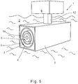
- Fig. 5 shows a fourth embodiment of a conductivity meter 1 for measuring an electrical conductivity of a liquid medium 2 with a housing 3, a conductive first measuring cell 7 and an inductive second measuring cell 8 in abstracted representation.
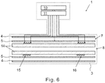
- Fig. 6 shows the embodiment in a sectional view.
- the conductivity meter 1 according to this embodiment no longer has only conductive measuring cells, but also the inductive second measuring cell 8.
- the first measuring cell 7 has a first conductivity measuring range and is formed by the first electrode 4 and the second electrode 5, wherein the two electrodes 4, 5 are cylindrical and arranged on the housing 3, whereby the first measuring cell 7 is arranged on the housing 3 is.
- the second measuring cell 8 has a second conductivity measuring range and a hollow cylindrical carrier 14, which is likewise arranged on the housing 3 and on which a transmitting coil 15 and a receiving coil 16 are wound.
- the cylindrical support 14, the first electrode 4 and the second electrode 5 are arranged coaxially with each other.
- the medium 2 is in particular between the first electrode 4 and the second electrode 5 and with the electrodes 4, 5 in contact. Furthermore, the medium 2 is also in the hollow-cylindrical carrier 14.
- the first measuring cell 7 and the second measuring cell 8 are designed such that the first conductivity measuring range and the second conductivity measuring range overlap one another, so that a first overlap conductivity range arises.
- the conductivity meter 1 has a control device 10 with a changeover switch 11, wherein the control device 10 is designed to control the changeover switch 11.
- the control device 10 is also designed to control the measuring cells 7, 8 beyond.
- the changeover switch 11 allows the use of the single control device 10 with the plurality of measuring cells 7, 8.
- the changeover switch 11 connects, controlled by the control device 10, the control device 10 either with the first measuring cell 7 or the second measuring cell 8, so that the control device 10 in Operation at a time in each case with one of the measuring cells 7, 8 determines a conductivity of the liquid medium 2.
- the connection between the control device 10 and one of the measuring cells 7, 8 is exclusive, which means that the other measuring cell is then not controllable by the control device 10.
- the design of the control device 10 for controlling the measuring cells 7, 8 comprises in particular the design for determining a conductivity of a medium with the measuring cells 7, 8.
- Fig. 7 shows a fifth embodiment of a conductivity meter 1 in an abstracted sectional view. This embodiment corresponds to the fourth embodiment, apart from the differences shown below, which is why, moreover, the comments on the fourth embodiment apply correspondingly to the fifth embodiment.
- the fifth exemplary embodiment of the conductivity meter 1 like the fourth exemplary embodiment, has a conductive first measuring cell 7 and an inductive second measuring cell 8.
- the measuring cells 7, 8 are not coaxial with each other, but arranged parallel to each other in a plane perpendicular to the support shaft 12.
- the arrangement parallel to each other is a special form of an arrangement next to each other.
- Fig. 8 shows a sixth embodiment of a conductivity meter 1 in an abstracted sectional view. This embodiment corresponds to the fourth embodiment, apart from the differences shown below, which is why the remarks to the fourth embodiment apply mutatis mutandis to the sixth embodiment.
- the sixth exemplary embodiment of the conductivity meter 1 like the fourth exemplary embodiment, has a conductive first measuring cell 7 and an inductive second measuring cell 8.
- the measuring cells 7, 8 are not coaxial with each other, but arranged coaxially in series one behind the other.
- the first measuring cell 7 is arranged in front of the second measuring cell 8, wherein in other embodiments, a reverse arrangement is given.
- Fig. 9 shows a seventh embodiment of a conductivity meter 1 in an abstracted sectional view. This embodiment corresponds to the fourth embodiment, apart from the differences shown below, which is why, for the rest, the statements on the fourth exemplary embodiment apply correspondingly to the seventh exemplary embodiment.
- the seventh embodiment of the conductivity meter 1 has, like the fourth embodiment, a conductive first measuring cell 7 and an inductive second measuring cell 8. However, the measuring cells 7, 8 are not arranged coaxially with one another, but the first measuring cell 7 is arranged below the second measuring cell 8 with respect to the holding shaft 12.
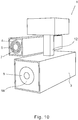
- Fig. 10 shows an eighth embodiment of a conductivity meter 1 in an abstracted representation. This embodiment corresponds to the fourth embodiment except for those shown below Differences, why, moreover, the comments on the fourth embodiment apply mutatis mutandis to the eighth embodiment.
- the eighth exemplary embodiment of the conductivity meter 1 like the fourth exemplary embodiment, has a conductive first measuring cell 7 and an inductive second measuring cell 8.
- the measuring cells 7, 8 are not arranged coaxially with each other, but is the first measuring cell 7 on one side of the holding shaft 12 and the second measuring cell 8 is arranged at one end of the holding shaft 12.
Landscapes
- Chemical & Material Sciences (AREA)
- Physics & Mathematics (AREA)
- General Physics & Mathematics (AREA)
- Life Sciences & Earth Sciences (AREA)
- Electrochemistry (AREA)
- Health & Medical Sciences (AREA)
- Chemical Kinetics & Catalysis (AREA)
- Analytical Chemistry (AREA)
- Biochemistry (AREA)
- General Health & Medical Sciences (AREA)
- Immunology (AREA)
- Pathology (AREA)
- Investigating Or Analyzing Materials By The Use Of Electric Means (AREA)
- Measurement Of Resistance Or Impedance (AREA)
Applications Claiming Priority (1)
| Application Number | Priority Date | Filing Date | Title |
|---|---|---|---|
| DE102016118526.4A DE102016118526A1 (de) | 2016-09-29 | 2016-09-29 | Leitfähigkeitsmessgerät zur Messung einer elektrischen Leitfähigkeit eines flüssigen Mediums |
Publications (2)
| Publication Number | Publication Date |
|---|---|
| EP3301436A1 true EP3301436A1 (fr) | 2018-04-04 |
| EP3301436B1 EP3301436B1 (fr) | 2023-06-07 |
Family
ID=59955409
Family Applications (1)
| Application Number | Title | Priority Date | Filing Date |
|---|---|---|---|
| EP17192511.8A Active EP3301436B1 (fr) | 2016-09-29 | 2017-09-22 | Appareil de mesure de conductivité destiné à mesurer une conductivité électrique d'un milieu liquide |
Country Status (4)
| Country | Link |
|---|---|
| US (1) | US10393686B2 (fr) |
| EP (1) | EP3301436B1 (fr) |
| CN (1) | CN107884623B (fr) |
| DE (1) | DE102016118526A1 (fr) |
Families Citing this family (1)
| Publication number | Priority date | Publication date | Assignee | Title |
|---|---|---|---|---|
| CN116165458B (zh) * | 2022-12-07 | 2023-11-07 | 湖南烯能新材料有限公司 | 一种石墨烯导电浆料的导电性能检测装置与方法 |
Citations (4)
| Publication number | Priority date | Publication date | Assignee | Title |
|---|---|---|---|---|
| US4949581A (en) * | 1989-06-15 | 1990-08-21 | Rosemount Inc. | Extended measurement capability transmitter having shared overpressure protection means |
| US20130214797A1 (en) * | 2012-01-20 | 2013-08-22 | Seuffer gmbH & Co. KG | Sensor apparatus for detecting properties of liquid |
| CN103675349A (zh) * | 2013-12-11 | 2014-03-26 | 江苏物联网研究发展中心 | 多量程的叉指电容加速度计 |
| US20140208859A1 (en) * | 2011-10-05 | 2014-07-31 | Canon Anelva Corporation | Diaphragm-type pressure gauge |
Family Cites Families (22)
| Publication number | Priority date | Publication date | Assignee | Title |
|---|---|---|---|---|
| US4808931A (en) * | 1987-04-13 | 1989-02-28 | General Technology, Inc. | Conductivity probe |
| DE3724104A1 (de) | 1987-07-21 | 1989-02-02 | Almatec Maschinenbau Gmbh | Druckluftbetriebene doppelmembranpumpe |
| CN1010252B (zh) * | 1988-01-11 | 1990-10-31 | 重庆大学 | 测量生物介电特性的六环电极装置 |
| DE9414343U1 (de) | 1994-09-03 | 1994-11-03 | Südwestsalz-Vertriebsgesellschaft mbH, 74177 Bad Friedrichshall | Glatteisfrühwarnsystem |
| DE19844489A1 (de) | 1998-09-29 | 2000-03-30 | Conducta Endress & Hauser | Verfahren zum Bestimmen der elektrischen Leitfähigkeit von Flüssigkeiten |
| DE10233312A1 (de) | 2002-07-22 | 2004-03-04 | Westfaliasurge Gmbh | Verfahren und Vorrichtung zur Bestimmung eines Volumenstroms während eines Melkvorgangs einer fließenden Milch |
| EP1444486A1 (fr) | 2001-11-16 | 2004-08-11 | WestfaliaSurge GmbH | Procede et dispositif permettant de determiner le debit volumetrique de lait s'ecoulant pendant le processus de traite |
| DE10163760C5 (de) * | 2001-12-28 | 2012-02-02 | Ebro Electronic Gmbh & Co. Kg | Vorrichtung und Verfahren zum Messen des Zustandes von Ölen und Fetten |
| EP1439388A1 (fr) * | 2003-01-20 | 2004-07-21 | Ecole Polytechnique Fédérale de Lausanne (EPFL) | Dispositif de mesure de la qualité et/ou de la dégradation d'un fluide; notamment d'une huile alimentaire |
| DE10353938A1 (de) | 2003-11-18 | 2005-06-23 | Fresenius Medical Care Deutschland Gmbh | Sensorkarte zur Bestimmung von Analyten in Flüssigkeits- oder Gasproben und Verfahren zur Herstellung einer solchen Sensorkarte |
| CN1776124B (zh) * | 2004-11-16 | 2010-12-22 | 玛博-移动自动控制公司 | 用于施工机器的控制传感器 |
| US7313502B2 (en) * | 2006-02-23 | 2007-12-25 | Rockwell Automation Technologies, Inc. | System and method to combine and weight multiple sensors with overlapping sensing range to create a measurement system utilized in a high integrity or safety environment |
| JP5310412B2 (ja) * | 2009-09-08 | 2013-10-09 | アイシン・エィ・ダブリュ株式会社 | コイルの非破壊検査方法 |
| PL2612140T3 (pl) * | 2010-09-03 | 2017-10-31 | Los Alamos Nat Security Llc | Zintegrowany, akustyczny separator faz i urządzenie oraz sposób monitorowania wielofazowej, płynnej kompozycji |
| FR2978828B1 (fr) * | 2011-08-02 | 2013-09-06 | Snecma | Capteur multi-electrode pour determiner la teneur en gaz dans un ecoulement diphasique |
| CN103251407A (zh) * | 2012-02-15 | 2013-08-21 | 乔国锋 | 多维阻抗断层扫描装置 |
| DE102012106551A1 (de) | 2012-07-19 | 2014-01-23 | Endress & Hauser Meßtechnik GmbH & Co. KG | Verfahren und Vorrichtung zur Kalibrierung eines Leitfähigkeitssensors |
| DE202012010505U1 (de) | 2012-11-02 | 2012-12-18 | Knürr GmbH | Wärmeübertragungsvorrichtung |
| DE102014109366A1 (de) | 2014-07-04 | 2016-01-07 | Endress + Hauser Conducta Gesellschaft für Mess- und Regeltechnik mbH + Co. KG | Induktiver Leitfähigkeitssensor zum Messen der spezifischen elektrischen Leitfähigkeit eines Mediums |
| CN105223379B (zh) * | 2015-09-29 | 2018-06-08 | 武汉工程大学 | 一种岩土渗流监测传感器及制备方法 |
| DE102015116993A1 (de) | 2015-10-06 | 2017-04-06 | Rainer Fakesch | Rettungssystem |
| DE102016104549B3 (de) | 2016-03-11 | 2016-11-03 | Krohne Messtechnik Gmbh | Verfahren zum Betreiben eines induktiven Leitfähigkeitssensors und diesbezüglicher induktiver Leitfähgikeitssensor |
-
2016
- 2016-09-29 DE DE102016118526.4A patent/DE102016118526A1/de not_active Withdrawn
-
2017
- 2017-09-22 EP EP17192511.8A patent/EP3301436B1/fr active Active
- 2017-09-29 US US15/720,148 patent/US10393686B2/en active Active
- 2017-09-29 CN CN201710906191.1A patent/CN107884623B/zh active Active
Patent Citations (4)
| Publication number | Priority date | Publication date | Assignee | Title |
|---|---|---|---|---|
| US4949581A (en) * | 1989-06-15 | 1990-08-21 | Rosemount Inc. | Extended measurement capability transmitter having shared overpressure protection means |
| US20140208859A1 (en) * | 2011-10-05 | 2014-07-31 | Canon Anelva Corporation | Diaphragm-type pressure gauge |
| US20130214797A1 (en) * | 2012-01-20 | 2013-08-22 | Seuffer gmbH & Co. KG | Sensor apparatus for detecting properties of liquid |
| CN103675349A (zh) * | 2013-12-11 | 2014-03-26 | 江苏物联网研究发展中心 | 多量程的叉指电容加速度计 |
Non-Patent Citations (1)
| Title |
|---|
| CONDUCTIVITY ANALYZER GUIDE: "Technical Information", 16 July 2009 (2009-07-16), pages 1 - 48, XP055442027, Retrieved from the Internet <URL:https://web-material3.yokogawa.com/TI12D08A01-01E_015.pdf> [retrieved on 20180118] * |
Also Published As
| Publication number | Publication date |
|---|---|
| US20180088065A1 (en) | 2018-03-29 |
| CN107884623A (zh) | 2018-04-06 |
| CN107884623B (zh) | 2022-12-27 |
| EP3301436B1 (fr) | 2023-06-07 |
| DE102016118526A1 (de) | 2018-03-29 |
| US10393686B2 (en) | 2019-08-27 |
Similar Documents
| Publication | Publication Date | Title |
|---|---|---|
| DE19917261C2 (de) | Elektromagnetische Durchflußmesseranordnung | |
| DE3433148C2 (de) | Anordnung zur Erfassung räumlicher Inhomogenitäten in einem Dielektrikum | |
| DE202013011690U1 (de) | Messwiderstand | |
| EP1462770A2 (fr) | Capteur de Hall avec décalage compensé | |
| DE2120407B2 (de) | Kapazitäts-Meßschaltung | |
| DE102014117821A1 (de) | Sensorsystem für ein Lenkrad eines Kraftfahrzeugs, Lenkrad mit einem solchen Sensorsystem und Verfahren zum Betrieb eines solchen Sensorsystems | |
| DE102021110370A1 (de) | Stromsensor | |
| EP3715796A1 (fr) | Dispositif de mesure de débit magnétique-inducteur pourvu d'agencement de mesure de conductivité et procédé de fonctionnement d'un dispositif de mesure de débit magnétique-inducteur pourvu d'agencement de mesure de conductivité | |
| DE60029573T2 (de) | Verbesserte stromfühleranordnung für niederspannungs-leistungsschalter | |
| EP0772054B1 (fr) | Procédé et appareil pour tester des structures de conducteur | |
| EP3301436A1 (fr) | Appareil de mesure de conductivité destiné à mesurer une conductivité électrique d'un milieu liquide | |
| DE102011106940A1 (de) | Positionsmesseinrichtung mit Randkompensation | |
| DE102015213784B4 (de) | Positionsmesssystem mit Empfängerspulen, die über Schaltmittel differentiell zusammenschaltbar sind | |
| EP0711978B1 (fr) | Procédé et dispositif pour déterminer la position réelle d'un objet par balayage capacitif | |
| CH693826A5 (de) | Vorrichtung an Kettenwirkmaschinen zum Positionieren eines Fadenfuehrers. | |
| DE102012013554A1 (de) | Einrichtung zum Abgleich von Metallsuchspulen | |
| DE102006038648B4 (de) | Vorrichtung zur Funktionskontrolle und/oder Kalibrierung eines Leitwertsensors und Verfahren zur Korrektur damit gemessener Werte | |
| EP3070436B1 (fr) | Systeme de mesure de position comprenant des moyens d'etalonnage | |
| DE102013224235A1 (de) | Sensorsystem zur kapazitiven Abstandsmessung | |
| DE102020122065B4 (de) | Kontaktanordnung mit einer Messvorrichtung zum Erfassen eines Kontaktierungszustands der Kontaktanordnung mittels eines akustischen Signals | |
| DE102008064544A1 (de) | Positions-/Wegmesssystem und Verfahren zur Bestimmung der Position eines Gebers | |
| DE102017127114A1 (de) | Konzept zum erfassen einer position eines schlittens eines linearen transportsystems | |
| CH711878B1 (de) | Verfahren und Vorrichtung zum Bestimmen des spezifischen Längenwiderstandes einer mehrdrähtigen Leitung. | |
| CH711009B1 (de) | Massverkörperung mit signalkompensierenden Markierungen. | |
| EP4671700A1 (fr) | Procédé de fonctionnement d'un débitmètre à induction magnétique et débitmètre à induction magnétique |
Legal Events
| Date | Code | Title | Description |
|---|---|---|---|
| PUAI | Public reference made under article 153(3) epc to a published international application that has entered the european phase |
Free format text: ORIGINAL CODE: 0009012 |
|
| STAA | Information on the status of an ep patent application or granted ep patent |
Free format text: STATUS: THE APPLICATION HAS BEEN PUBLISHED |
|
| AK | Designated contracting states |
Kind code of ref document: A1 Designated state(s): AL AT BE BG CH CY CZ DE DK EE ES FI FR GB GR HR HU IE IS IT LI LT LU LV MC MK MT NL NO PL PT RO RS SE SI SK SM TR |
|
| AX | Request for extension of the european patent |
Extension state: BA ME |
|
| STAA | Information on the status of an ep patent application or granted ep patent |
Free format text: STATUS: REQUEST FOR EXAMINATION WAS MADE |
|
| 17P | Request for examination filed |
Effective date: 20181001 |
|
| RBV | Designated contracting states (corrected) |
Designated state(s): AL AT BE BG CH CY CZ DE DK EE ES FI FR GB GR HR HU IE IS IT LI LT LU LV MC MK MT NL NO PL PT RO RS SE SI SK SM TR |
|
| STAA | Information on the status of an ep patent application or granted ep patent |
Free format text: STATUS: EXAMINATION IS IN PROGRESS |
|
| 17Q | First examination report despatched |
Effective date: 20200330 |
|
| GRAP | Despatch of communication of intention to grant a patent |
Free format text: ORIGINAL CODE: EPIDOSNIGR1 |
|
| STAA | Information on the status of an ep patent application or granted ep patent |
Free format text: STATUS: GRANT OF PATENT IS INTENDED |
|
| INTG | Intention to grant announced |
Effective date: 20230119 |
|
| GRAS | Grant fee paid |
Free format text: ORIGINAL CODE: EPIDOSNIGR3 |
|
| GRAA | (expected) grant |
Free format text: ORIGINAL CODE: 0009210 |
|
| STAA | Information on the status of an ep patent application or granted ep patent |
Free format text: STATUS: THE PATENT HAS BEEN GRANTED |
|
| AK | Designated contracting states |
Kind code of ref document: B1 Designated state(s): AL AT BE BG CH CY CZ DE DK EE ES FI FR GB GR HR HU IE IS IT LI LT LU LV MC MK MT NL NO PL PT RO RS SE SI SK SM TR |
|
| REG | Reference to a national code |
Ref country code: GB Ref legal event code: FG4D Free format text: NOT ENGLISH |
|
| REG | Reference to a national code |
Ref country code: CH Ref legal event code: EP Ref country code: AT Ref legal event code: REF Ref document number: 1576566 Country of ref document: AT Kind code of ref document: T Effective date: 20230615 |
|
| REG | Reference to a national code |
Ref country code: DE Ref legal event code: R096 Ref document number: 502017014802 Country of ref document: DE |
|
| P01 | Opt-out of the competence of the unified patent court (upc) registered |
Effective date: 20230816 |
|
| REG | Reference to a national code |
Ref country code: LT Ref legal event code: MG9D |
|
| REG | Reference to a national code |
Ref country code: NL Ref legal event code: MP Effective date: 20230607 |
|
| PG25 | Lapsed in a contracting state [announced via postgrant information from national office to epo] |
Ref country code: SE Free format text: LAPSE BECAUSE OF FAILURE TO SUBMIT A TRANSLATION OF THE DESCRIPTION OR TO PAY THE FEE WITHIN THE PRESCRIBED TIME-LIMIT Effective date: 20230607 Ref country code: NO Free format text: LAPSE BECAUSE OF FAILURE TO SUBMIT A TRANSLATION OF THE DESCRIPTION OR TO PAY THE FEE WITHIN THE PRESCRIBED TIME-LIMIT Effective date: 20230907 Ref country code: ES Free format text: LAPSE BECAUSE OF FAILURE TO SUBMIT A TRANSLATION OF THE DESCRIPTION OR TO PAY THE FEE WITHIN THE PRESCRIBED TIME-LIMIT Effective date: 20230607 |
|
| PG25 | Lapsed in a contracting state [announced via postgrant information from national office to epo] |
Ref country code: RS Free format text: LAPSE BECAUSE OF FAILURE TO SUBMIT A TRANSLATION OF THE DESCRIPTION OR TO PAY THE FEE WITHIN THE PRESCRIBED TIME-LIMIT Effective date: 20230607 Ref country code: NL Free format text: LAPSE BECAUSE OF FAILURE TO SUBMIT A TRANSLATION OF THE DESCRIPTION OR TO PAY THE FEE WITHIN THE PRESCRIBED TIME-LIMIT Effective date: 20230607 Ref country code: LV Free format text: LAPSE BECAUSE OF FAILURE TO SUBMIT A TRANSLATION OF THE DESCRIPTION OR TO PAY THE FEE WITHIN THE PRESCRIBED TIME-LIMIT Effective date: 20230607 Ref country code: LT Free format text: LAPSE BECAUSE OF FAILURE TO SUBMIT A TRANSLATION OF THE DESCRIPTION OR TO PAY THE FEE WITHIN THE PRESCRIBED TIME-LIMIT Effective date: 20230607 Ref country code: HR Free format text: LAPSE BECAUSE OF FAILURE TO SUBMIT A TRANSLATION OF THE DESCRIPTION OR TO PAY THE FEE WITHIN THE PRESCRIBED TIME-LIMIT Effective date: 20230607 Ref country code: GR Free format text: LAPSE BECAUSE OF FAILURE TO SUBMIT A TRANSLATION OF THE DESCRIPTION OR TO PAY THE FEE WITHIN THE PRESCRIBED TIME-LIMIT Effective date: 20230908 |
|
| PG25 | Lapsed in a contracting state [announced via postgrant information from national office to epo] |
Ref country code: FI Free format text: LAPSE BECAUSE OF FAILURE TO SUBMIT A TRANSLATION OF THE DESCRIPTION OR TO PAY THE FEE WITHIN THE PRESCRIBED TIME-LIMIT Effective date: 20230607 |
|
| PG25 | Lapsed in a contracting state [announced via postgrant information from national office to epo] |
Ref country code: SK Free format text: LAPSE BECAUSE OF FAILURE TO SUBMIT A TRANSLATION OF THE DESCRIPTION OR TO PAY THE FEE WITHIN THE PRESCRIBED TIME-LIMIT Effective date: 20230607 |
|
| PG25 | Lapsed in a contracting state [announced via postgrant information from national office to epo] |
Ref country code: IS Free format text: LAPSE BECAUSE OF FAILURE TO SUBMIT A TRANSLATION OF THE DESCRIPTION OR TO PAY THE FEE WITHIN THE PRESCRIBED TIME-LIMIT Effective date: 20231007 |
|
| PG25 | Lapsed in a contracting state [announced via postgrant information from national office to epo] |
Ref country code: SM Free format text: LAPSE BECAUSE OF FAILURE TO SUBMIT A TRANSLATION OF THE DESCRIPTION OR TO PAY THE FEE WITHIN THE PRESCRIBED TIME-LIMIT Effective date: 20230607 Ref country code: SK Free format text: LAPSE BECAUSE OF FAILURE TO SUBMIT A TRANSLATION OF THE DESCRIPTION OR TO PAY THE FEE WITHIN THE PRESCRIBED TIME-LIMIT Effective date: 20230607 Ref country code: RO Free format text: LAPSE BECAUSE OF FAILURE TO SUBMIT A TRANSLATION OF THE DESCRIPTION OR TO PAY THE FEE WITHIN THE PRESCRIBED TIME-LIMIT Effective date: 20230607 Ref country code: PT Free format text: LAPSE BECAUSE OF FAILURE TO SUBMIT A TRANSLATION OF THE DESCRIPTION OR TO PAY THE FEE WITHIN THE PRESCRIBED TIME-LIMIT Effective date: 20231009 Ref country code: IS Free format text: LAPSE BECAUSE OF FAILURE TO SUBMIT A TRANSLATION OF THE DESCRIPTION OR TO PAY THE FEE WITHIN THE PRESCRIBED TIME-LIMIT Effective date: 20231007 Ref country code: EE Free format text: LAPSE BECAUSE OF FAILURE TO SUBMIT A TRANSLATION OF THE DESCRIPTION OR TO PAY THE FEE WITHIN THE PRESCRIBED TIME-LIMIT Effective date: 20230607 Ref country code: CZ Free format text: LAPSE BECAUSE OF FAILURE TO SUBMIT A TRANSLATION OF THE DESCRIPTION OR TO PAY THE FEE WITHIN THE PRESCRIBED TIME-LIMIT Effective date: 20230607 |
|
| PG25 | Lapsed in a contracting state [announced via postgrant information from national office to epo] |
Ref country code: PL Free format text: LAPSE BECAUSE OF FAILURE TO SUBMIT A TRANSLATION OF THE DESCRIPTION OR TO PAY THE FEE WITHIN THE PRESCRIBED TIME-LIMIT Effective date: 20230607 |
|
| REG | Reference to a national code |
Ref country code: DE Ref legal event code: R097 Ref document number: 502017014802 Country of ref document: DE |
|
| PLBE | No opposition filed within time limit |
Free format text: ORIGINAL CODE: 0009261 |
|
| STAA | Information on the status of an ep patent application or granted ep patent |
Free format text: STATUS: NO OPPOSITION FILED WITHIN TIME LIMIT |
|
| PG25 | Lapsed in a contracting state [announced via postgrant information from national office to epo] |
Ref country code: DK Free format text: LAPSE BECAUSE OF FAILURE TO SUBMIT A TRANSLATION OF THE DESCRIPTION OR TO PAY THE FEE WITHIN THE PRESCRIBED TIME-LIMIT Effective date: 20230607 |
|
| REG | Reference to a national code |
Ref country code: CH Ref legal event code: PL |
|
| PG25 | Lapsed in a contracting state [announced via postgrant information from national office to epo] |
Ref country code: SI Free format text: LAPSE BECAUSE OF FAILURE TO SUBMIT A TRANSLATION OF THE DESCRIPTION OR TO PAY THE FEE WITHIN THE PRESCRIBED TIME-LIMIT Effective date: 20230607 |
|
| 26N | No opposition filed |
Effective date: 20240308 |
|
| PG25 | Lapsed in a contracting state [announced via postgrant information from national office to epo] |
Ref country code: LU Free format text: LAPSE BECAUSE OF NON-PAYMENT OF DUE FEES Effective date: 20230922 |
|
| REG | Reference to a national code |
Ref country code: BE Ref legal event code: MM Effective date: 20230930 |
|
| GBPC | Gb: european patent ceased through non-payment of renewal fee |
Effective date: 20230922 |
|
| PG25 | Lapsed in a contracting state [announced via postgrant information from national office to epo] |
Ref country code: SI Free format text: LAPSE BECAUSE OF FAILURE TO SUBMIT A TRANSLATION OF THE DESCRIPTION OR TO PAY THE FEE WITHIN THE PRESCRIBED TIME-LIMIT Effective date: 20230607 Ref country code: LU Free format text: LAPSE BECAUSE OF NON-PAYMENT OF DUE FEES Effective date: 20230922 Ref country code: IT Free format text: LAPSE BECAUSE OF FAILURE TO SUBMIT A TRANSLATION OF THE DESCRIPTION OR TO PAY THE FEE WITHIN THE PRESCRIBED TIME-LIMIT Effective date: 20230607 Ref country code: MC Free format text: LAPSE BECAUSE OF FAILURE TO SUBMIT A TRANSLATION OF THE DESCRIPTION OR TO PAY THE FEE WITHIN THE PRESCRIBED TIME-LIMIT Effective date: 20230607 |
|
| REG | Reference to a national code |
Ref country code: IE Ref legal event code: MM4A |
|
| PG25 | Lapsed in a contracting state [announced via postgrant information from national office to epo] |
Ref country code: IE Free format text: LAPSE BECAUSE OF NON-PAYMENT OF DUE FEES Effective date: 20230922 |
|
| PG25 | Lapsed in a contracting state [announced via postgrant information from national office to epo] |
Ref country code: GB Free format text: LAPSE BECAUSE OF NON-PAYMENT OF DUE FEES Effective date: 20230922 |
|
| PG25 | Lapsed in a contracting state [announced via postgrant information from national office to epo] |
Ref country code: CH Free format text: LAPSE BECAUSE OF NON-PAYMENT OF DUE FEES Effective date: 20230930 |
|
| PG25 | Lapsed in a contracting state [announced via postgrant information from national office to epo] |
Ref country code: IE Free format text: LAPSE BECAUSE OF NON-PAYMENT OF DUE FEES Effective date: 20230922 Ref country code: GB Free format text: LAPSE BECAUSE OF NON-PAYMENT OF DUE FEES Effective date: 20230922 Ref country code: FR Free format text: LAPSE BECAUSE OF NON-PAYMENT OF DUE FEES Effective date: 20230930 Ref country code: CH Free format text: LAPSE BECAUSE OF NON-PAYMENT OF DUE FEES Effective date: 20230930 |
|
| PG25 | Lapsed in a contracting state [announced via postgrant information from national office to epo] |
Ref country code: BE Free format text: LAPSE BECAUSE OF NON-PAYMENT OF DUE FEES Effective date: 20230930 |
|
| PG25 | Lapsed in a contracting state [announced via postgrant information from national office to epo] |
Ref country code: BG Free format text: LAPSE BECAUSE OF FAILURE TO SUBMIT A TRANSLATION OF THE DESCRIPTION OR TO PAY THE FEE WITHIN THE PRESCRIBED TIME-LIMIT Effective date: 20230607 |
|
| REG | Reference to a national code |
Ref country code: AT Ref legal event code: MM01 Ref document number: 1576566 Country of ref document: AT Kind code of ref document: T Effective date: 20230922 |
|
| PG25 | Lapsed in a contracting state [announced via postgrant information from national office to epo] |
Ref country code: BG Free format text: LAPSE BECAUSE OF FAILURE TO SUBMIT A TRANSLATION OF THE DESCRIPTION OR TO PAY THE FEE WITHIN THE PRESCRIBED TIME-LIMIT Effective date: 20230607 |
|
| PG25 | Lapsed in a contracting state [announced via postgrant information from national office to epo] |
Ref country code: AT Free format text: LAPSE BECAUSE OF NON-PAYMENT OF DUE FEES Effective date: 20230922 |
|
| PG25 | Lapsed in a contracting state [announced via postgrant information from national office to epo] |
Ref country code: AT Free format text: LAPSE BECAUSE OF NON-PAYMENT OF DUE FEES Effective date: 20230922 |
|
| PG25 | Lapsed in a contracting state [announced via postgrant information from national office to epo] |
Ref country code: CY Free format text: LAPSE BECAUSE OF FAILURE TO SUBMIT A TRANSLATION OF THE DESCRIPTION OR TO PAY THE FEE WITHIN THE PRESCRIBED TIME-LIMIT; INVALID AB INITIO Effective date: 20170922 |
|
| PG25 | Lapsed in a contracting state [announced via postgrant information from national office to epo] |
Ref country code: HU Free format text: LAPSE BECAUSE OF FAILURE TO SUBMIT A TRANSLATION OF THE DESCRIPTION OR TO PAY THE FEE WITHIN THE PRESCRIBED TIME-LIMIT; INVALID AB INITIO Effective date: 20170922 |
|
| PG25 | Lapsed in a contracting state [announced via postgrant information from national office to epo] |
Ref country code: TR Free format text: LAPSE BECAUSE OF FAILURE TO SUBMIT A TRANSLATION OF THE DESCRIPTION OR TO PAY THE FEE WITHIN THE PRESCRIBED TIME-LIMIT Effective date: 20230607 |
|
| PGFP | Annual fee paid to national office [announced via postgrant information from national office to epo] |
Ref country code: DE Payment date: 20251110 Year of fee payment: 9 |