EP3301669A2 - Dispositif d'affichage et procédé de transition de sous-pixels - Google Patents
Dispositif d'affichage et procédé de transition de sous-pixels Download PDFInfo
- Publication number
- EP3301669A2 EP3301669A2 EP17194155.2A EP17194155A EP3301669A2 EP 3301669 A2 EP3301669 A2 EP 3301669A2 EP 17194155 A EP17194155 A EP 17194155A EP 3301669 A2 EP3301669 A2 EP 3301669A2
- Authority
- EP
- European Patent Office
- Prior art keywords
- sub
- pixel
- color
- horizontal period
- transition
- Prior art date
- Legal status (The legal status is an assumption and is not a legal conclusion. Google has not performed a legal analysis and makes no representation as to the accuracy of the status listed.)
- Ceased
Links
Images


Classifications
-
- G—PHYSICS
- G09—EDUCATION; CRYPTOGRAPHY; DISPLAY; ADVERTISING; SEALS
- G09G—ARRANGEMENTS OR CIRCUITS FOR CONTROL OF INDICATING DEVICES USING STATIC MEANS TO PRESENT VARIABLE INFORMATION
- G09G3/00—Control arrangements or circuits, of interest only in connection with visual indicators other than cathode-ray tubes
- G09G3/20—Control arrangements or circuits, of interest only in connection with visual indicators other than cathode-ray tubes for presentation of an assembly of a number of characters, e.g. a page, by composing the assembly by combination of individual elements arranged in a matrix no fixed position being assigned to or needed to be assigned to the individual characters or partial characters
- G09G3/2003—Display of colours
-
- G—PHYSICS
- G09—EDUCATION; CRYPTOGRAPHY; DISPLAY; ADVERTISING; SEALS
- G09G—ARRANGEMENTS OR CIRCUITS FOR CONTROL OF INDICATING DEVICES USING STATIC MEANS TO PRESENT VARIABLE INFORMATION
- G09G3/00—Control arrangements or circuits, of interest only in connection with visual indicators other than cathode-ray tubes
- G09G3/20—Control arrangements or circuits, of interest only in connection with visual indicators other than cathode-ray tubes for presentation of an assembly of a number of characters, e.g. a page, by composing the assembly by combination of individual elements arranged in a matrix no fixed position being assigned to or needed to be assigned to the individual characters or partial characters
- G09G3/2007—Display of intermediate tones
- G09G3/2074—Display of intermediate tones using sub-pixels
-
- G—PHYSICS
- G09—EDUCATION; CRYPTOGRAPHY; DISPLAY; ADVERTISING; SEALS
- G09G—ARRANGEMENTS OR CIRCUITS FOR CONTROL OF INDICATING DEVICES USING STATIC MEANS TO PRESENT VARIABLE INFORMATION
- G09G3/00—Control arrangements or circuits, of interest only in connection with visual indicators other than cathode-ray tubes
- G09G3/20—Control arrangements or circuits, of interest only in connection with visual indicators other than cathode-ray tubes for presentation of an assembly of a number of characters, e.g. a page, by composing the assembly by combination of individual elements arranged in a matrix no fixed position being assigned to or needed to be assigned to the individual characters or partial characters
- G09G3/22—Control arrangements or circuits, of interest only in connection with visual indicators other than cathode-ray tubes for presentation of an assembly of a number of characters, e.g. a page, by composing the assembly by combination of individual elements arranged in a matrix no fixed position being assigned to or needed to be assigned to the individual characters or partial characters using controlled light sources
- G09G3/30—Control arrangements or circuits, of interest only in connection with visual indicators other than cathode-ray tubes for presentation of an assembly of a number of characters, e.g. a page, by composing the assembly by combination of individual elements arranged in a matrix no fixed position being assigned to or needed to be assigned to the individual characters or partial characters using controlled light sources using electroluminescent panels
- G09G3/32—Control arrangements or circuits, of interest only in connection with visual indicators other than cathode-ray tubes for presentation of an assembly of a number of characters, e.g. a page, by composing the assembly by combination of individual elements arranged in a matrix no fixed position being assigned to or needed to be assigned to the individual characters or partial characters using controlled light sources using electroluminescent panels semiconductive, e.g. using light-emitting diodes [LED]
- G09G3/3208—Control arrangements or circuits, of interest only in connection with visual indicators other than cathode-ray tubes for presentation of an assembly of a number of characters, e.g. a page, by composing the assembly by combination of individual elements arranged in a matrix no fixed position being assigned to or needed to be assigned to the individual characters or partial characters using controlled light sources using electroluminescent panels semiconductive, e.g. using light-emitting diodes [LED] organic, e.g. using organic light-emitting diodes [OLED]
- G09G3/3266—Details of drivers for scan electrodes
-
- G—PHYSICS
- G09—EDUCATION; CRYPTOGRAPHY; DISPLAY; ADVERTISING; SEALS
- G09G—ARRANGEMENTS OR CIRCUITS FOR CONTROL OF INDICATING DEVICES USING STATIC MEANS TO PRESENT VARIABLE INFORMATION
- G09G3/00—Control arrangements or circuits, of interest only in connection with visual indicators other than cathode-ray tubes
- G09G3/20—Control arrangements or circuits, of interest only in connection with visual indicators other than cathode-ray tubes for presentation of an assembly of a number of characters, e.g. a page, by composing the assembly by combination of individual elements arranged in a matrix no fixed position being assigned to or needed to be assigned to the individual characters or partial characters
- G09G3/34—Control arrangements or circuits, of interest only in connection with visual indicators other than cathode-ray tubes for presentation of an assembly of a number of characters, e.g. a page, by composing the assembly by combination of individual elements arranged in a matrix no fixed position being assigned to or needed to be assigned to the individual characters or partial characters by control of light from an independent source
- G09G3/36—Control arrangements or circuits, of interest only in connection with visual indicators other than cathode-ray tubes for presentation of an assembly of a number of characters, e.g. a page, by composing the assembly by combination of individual elements arranged in a matrix no fixed position being assigned to or needed to be assigned to the individual characters or partial characters by control of light from an independent source using liquid crystals
- G09G3/3611—Control of matrices with row and column drivers
- G09G3/3614—Control of polarity reversal in general
-
- G—PHYSICS
- G09—EDUCATION; CRYPTOGRAPHY; DISPLAY; ADVERTISING; SEALS
- G09G—ARRANGEMENTS OR CIRCUITS FOR CONTROL OF INDICATING DEVICES USING STATIC MEANS TO PRESENT VARIABLE INFORMATION
- G09G3/00—Control arrangements or circuits, of interest only in connection with visual indicators other than cathode-ray tubes
- G09G3/20—Control arrangements or circuits, of interest only in connection with visual indicators other than cathode-ray tubes for presentation of an assembly of a number of characters, e.g. a page, by composing the assembly by combination of individual elements arranged in a matrix no fixed position being assigned to or needed to be assigned to the individual characters or partial characters
- G09G3/34—Control arrangements or circuits, of interest only in connection with visual indicators other than cathode-ray tubes for presentation of an assembly of a number of characters, e.g. a page, by composing the assembly by combination of individual elements arranged in a matrix no fixed position being assigned to or needed to be assigned to the individual characters or partial characters by control of light from an independent source
- G09G3/36—Control arrangements or circuits, of interest only in connection with visual indicators other than cathode-ray tubes for presentation of an assembly of a number of characters, e.g. a page, by composing the assembly by combination of individual elements arranged in a matrix no fixed position being assigned to or needed to be assigned to the individual characters or partial characters by control of light from an independent source using liquid crystals
- G09G3/3611—Control of matrices with row and column drivers
- G09G3/3674—Details of drivers for scan electrodes
- G09G3/3677—Details of drivers for scan electrodes suitable for active matrices only
-
- G—PHYSICS
- G09—EDUCATION; CRYPTOGRAPHY; DISPLAY; ADVERTISING; SEALS
- G09G—ARRANGEMENTS OR CIRCUITS FOR CONTROL OF INDICATING DEVICES USING STATIC MEANS TO PRESENT VARIABLE INFORMATION
- G09G2230/00—Details of flat display driving waveforms
-
- G—PHYSICS
- G09—EDUCATION; CRYPTOGRAPHY; DISPLAY; ADVERTISING; SEALS
- G09G—ARRANGEMENTS OR CIRCUITS FOR CONTROL OF INDICATING DEVICES USING STATIC MEANS TO PRESENT VARIABLE INFORMATION
- G09G2300/00—Aspects of the constitution of display devices
- G09G2300/04—Structural and physical details of display devices
- G09G2300/0439—Pixel structures
- G09G2300/0452—Details of colour pixel setup, e.g. pixel composed of a red, a blue and two green components
-
- G—PHYSICS
- G09—EDUCATION; CRYPTOGRAPHY; DISPLAY; ADVERTISING; SEALS
- G09G—ARRANGEMENTS OR CIRCUITS FOR CONTROL OF INDICATING DEVICES USING STATIC MEANS TO PRESENT VARIABLE INFORMATION
- G09G2310/00—Command of the display device
- G09G2310/02—Addressing, scanning or driving the display screen or processing steps related thereto
- G09G2310/0264—Details of driving circuits
- G09G2310/027—Details of drivers for data electrodes, the drivers handling digital grey scale data, e.g. use of D/A converters
-
- G—PHYSICS
- G09—EDUCATION; CRYPTOGRAPHY; DISPLAY; ADVERTISING; SEALS
- G09G—ARRANGEMENTS OR CIRCUITS FOR CONTROL OF INDICATING DEVICES USING STATIC MEANS TO PRESENT VARIABLE INFORMATION
- G09G2310/00—Command of the display device
- G09G2310/02—Addressing, scanning or driving the display screen or processing steps related thereto
- G09G2310/0264—Details of driving circuits
- G09G2310/0297—Special arrangements with multiplexing or demultiplexing of display data in the drivers for data electrodes, in a pre-processing circuitry delivering display data to said drivers or in the matrix panel, e.g. multiplexing plural data signals to one D/A converter or demultiplexing the D/A converter output to multiple columns
-
- G—PHYSICS
- G09—EDUCATION; CRYPTOGRAPHY; DISPLAY; ADVERTISING; SEALS
- G09G—ARRANGEMENTS OR CIRCUITS FOR CONTROL OF INDICATING DEVICES USING STATIC MEANS TO PRESENT VARIABLE INFORMATION
- G09G2310/00—Command of the display device
- G09G2310/08—Details of timing specific for flat panels, other than clock recovery
-
- G—PHYSICS
- G09—EDUCATION; CRYPTOGRAPHY; DISPLAY; ADVERTISING; SEALS
- G09G—ARRANGEMENTS OR CIRCUITS FOR CONTROL OF INDICATING DEVICES USING STATIC MEANS TO PRESENT VARIABLE INFORMATION
- G09G2320/00—Control of display operating conditions
- G09G2320/02—Improving the quality of display appearance
- G09G2320/0242—Compensation of deficiencies in the appearance of colours
-
- G—PHYSICS
- G09—EDUCATION; CRYPTOGRAPHY; DISPLAY; ADVERTISING; SEALS
- G09G—ARRANGEMENTS OR CIRCUITS FOR CONTROL OF INDICATING DEVICES USING STATIC MEANS TO PRESENT VARIABLE INFORMATION
- G09G2320/00—Control of display operating conditions
- G09G2320/02—Improving the quality of display appearance
- G09G2320/0247—Flicker reduction other than flicker reduction circuits used for single beam cathode-ray tubes
-
- G—PHYSICS
- G09—EDUCATION; CRYPTOGRAPHY; DISPLAY; ADVERTISING; SEALS
- G09G—ARRANGEMENTS OR CIRCUITS FOR CONTROL OF INDICATING DEVICES USING STATIC MEANS TO PRESENT VARIABLE INFORMATION
- G09G2320/00—Control of display operating conditions
- G09G2320/02—Improving the quality of display appearance
- G09G2320/0257—Reduction of after-image effects
-
- G—PHYSICS
- G09—EDUCATION; CRYPTOGRAPHY; DISPLAY; ADVERTISING; SEALS
- G09G—ARRANGEMENTS OR CIRCUITS FOR CONTROL OF INDICATING DEVICES USING STATIC MEANS TO PRESENT VARIABLE INFORMATION
- G09G2330/00—Aspects of power supply; Aspects of display protection and defect management
- G09G2330/02—Details of power systems and of start or stop of display operation
- G09G2330/021—Power management, e.g. power saving
-
- G—PHYSICS
- G09—EDUCATION; CRYPTOGRAPHY; DISPLAY; ADVERTISING; SEALS
- G09G—ARRANGEMENTS OR CIRCUITS FOR CONTROL OF INDICATING DEVICES USING STATIC MEANS TO PRESENT VARIABLE INFORMATION
- G09G2360/00—Aspects of the architecture of display systems
- G09G2360/08—Power processing, i.e. workload management for processors involved in display operations, such as CPUs or GPUs
-
- G—PHYSICS
- G09—EDUCATION; CRYPTOGRAPHY; DISPLAY; ADVERTISING; SEALS
- G09G—ARRANGEMENTS OR CIRCUITS FOR CONTROL OF INDICATING DEVICES USING STATIC MEANS TO PRESENT VARIABLE INFORMATION
- G09G3/00—Control arrangements or circuits, of interest only in connection with visual indicators other than cathode-ray tubes
- G09G3/20—Control arrangements or circuits, of interest only in connection with visual indicators other than cathode-ray tubes for presentation of an assembly of a number of characters, e.g. a page, by composing the assembly by combination of individual elements arranged in a matrix no fixed position being assigned to or needed to be assigned to the individual characters or partial characters
- G09G3/22—Control arrangements or circuits, of interest only in connection with visual indicators other than cathode-ray tubes for presentation of an assembly of a number of characters, e.g. a page, by composing the assembly by combination of individual elements arranged in a matrix no fixed position being assigned to or needed to be assigned to the individual characters or partial characters using controlled light sources
- G09G3/30—Control arrangements or circuits, of interest only in connection with visual indicators other than cathode-ray tubes for presentation of an assembly of a number of characters, e.g. a page, by composing the assembly by combination of individual elements arranged in a matrix no fixed position being assigned to or needed to be assigned to the individual characters or partial characters using controlled light sources using electroluminescent panels
- G09G3/32—Control arrangements or circuits, of interest only in connection with visual indicators other than cathode-ray tubes for presentation of an assembly of a number of characters, e.g. a page, by composing the assembly by combination of individual elements arranged in a matrix no fixed position being assigned to or needed to be assigned to the individual characters or partial characters using controlled light sources using electroluminescent panels semiconductive, e.g. using light-emitting diodes [LED]
- G09G3/3208—Control arrangements or circuits, of interest only in connection with visual indicators other than cathode-ray tubes for presentation of an assembly of a number of characters, e.g. a page, by composing the assembly by combination of individual elements arranged in a matrix no fixed position being assigned to or needed to be assigned to the individual characters or partial characters using controlled light sources using electroluminescent panels semiconductive, e.g. using light-emitting diodes [LED] organic, e.g. using organic light-emitting diodes [OLED]
-
- G—PHYSICS
- G09—EDUCATION; CRYPTOGRAPHY; DISPLAY; ADVERTISING; SEALS
- G09G—ARRANGEMENTS OR CIRCUITS FOR CONTROL OF INDICATING DEVICES USING STATIC MEANS TO PRESENT VARIABLE INFORMATION
- G09G3/00—Control arrangements or circuits, of interest only in connection with visual indicators other than cathode-ray tubes
- G09G3/20—Control arrangements or circuits, of interest only in connection with visual indicators other than cathode-ray tubes for presentation of an assembly of a number of characters, e.g. a page, by composing the assembly by combination of individual elements arranged in a matrix no fixed position being assigned to or needed to be assigned to the individual characters or partial characters
- G09G3/34—Control arrangements or circuits, of interest only in connection with visual indicators other than cathode-ray tubes for presentation of an assembly of a number of characters, e.g. a page, by composing the assembly by combination of individual elements arranged in a matrix no fixed position being assigned to or needed to be assigned to the individual characters or partial characters by control of light from an independent source
- G09G3/36—Control arrangements or circuits, of interest only in connection with visual indicators other than cathode-ray tubes for presentation of an assembly of a number of characters, e.g. a page, by composing the assembly by combination of individual elements arranged in a matrix no fixed position being assigned to or needed to be assigned to the individual characters or partial characters by control of light from an independent source using liquid crystals
- G09G3/3607—Control arrangements or circuits, of interest only in connection with visual indicators other than cathode-ray tubes for presentation of an assembly of a number of characters, e.g. a page, by composing the assembly by combination of individual elements arranged in a matrix no fixed position being assigned to or needed to be assigned to the individual characters or partial characters by control of light from an independent source using liquid crystals for displaying colours or for displaying grey scales with a specific pixel layout, e.g. using sub-pixels
Definitions
- the present disclosure relates to a display device, and more particularly, to a display device comprising sub-pixels and a method of using the same.
- LCD liquid crystal display
- PDP plasma display panel
- OLED organic light emitting diode
- a display panel in such a display device includes an active area AA that provides an image to a user and a non-active area NA that is a peripheral area of the active area AA.
- the display panel is typically manufactured by bonding a first substrate serving as an array substrate on which a thin film transistor is formed and a pixel area is defined and a second substrate serving as an upper substrate or a protection substrate on which a black matrix and/or a color filter layer is formed.
- the array substrate or first substrate on which the thin film transistor is formed includes a plurality of gate lines GL extended in a first direction and a plurality of data lines DL extended in a second direction that is perpendicular to the first direction, and each pixel P or sub-pixel SP is defined by a gate line and a data line.
- a gate or source electrode of each of the thin film transistors may be connected to a gate line and a data line.
- the array substrate or first substrate includes a gate driver (e.g., driving circuit) or a data driving circuit provided in the non-active area or outside the panel to supply a gate signal and a data signal required for driving each pixel to each gate line and each data line.
- a gate driver e.g., driving circuit
- a data driving circuit provided in the non-active area or outside the panel to supply a gate signal and a data signal required for driving each pixel to each gate line and each data line.
- each of a plurality of sub-pixels defined at intersections between gate lines and data lines is configured to display one of red (R), green (G), and blue (B).
- a period in which a gate driving signal is applied to a single gate line may be referred to as a horizontal period H.
- a data signal (source signal) is applied to three sub-pixels including R, G, and B and an image is displayed on the corresponding sub-pixels.
- a change of image display between sub-pixels of respective colors may be referred to as a sub-pixel transition or a transition.
- the supply of a source signal to a data line needs to be dynamically switched to perform a sub-pixel transition and, thus, may affect image quality and power consumption. Therefore, it is desirable to optimize a transition method with consideration for display characteristics and power consumption.
- embodiments are directed to a display device and a method of sub-pixel transition that substantially address one or more of the problems due to limitations and disadvantages of the related art.
- An aspect provides a display device capable of suppressing defective display during a sub-pixel transition in a display panel.
- Another aspect provides a display device capable of suppressing defective display caused by a sub-pixel transition by uniformly performing a transition between sub-pixels displaying different colors, and a method of transition.
- Yet another aspect provides a display device capable of reducing defective display caused by a sub-pixel transition by reducing a transition between sub-pixels, and a method of transition.
- Still another aspect provides a display device and a method of transition.
- a display device comprises a display panel including gate lines, data lines, a first color sub-pixel, a second color sub-pixel, and a third color sub-pixel, wherein the first color sub-pixel, the second color sub-pixel, and the third color sub-pixel are defined by intersections between the data lines and gate lines; a data driver configured to apply a source signal to the data lines; and a transition control unit configured to control a sequential supplying of the source signal to the first color sub-pixel, the second color sub-pixel, and the third color sub-pixel during a kth horizontal period H#k and a sequential supplying of the source signal to the third color sub-pixel, the first color sub-pixel, and the second color sub-pixel during a k+1th horizontal period H#(k+1).
- a method of a sub-pixel transition in a display device which includes a first color sub-pixel, a second color sub-pixel, and a third color sub-pixel, and a transition control unit configured to control transitions for the first, second, and third sub-pixels, comprises time-dividing a kth horizontal period into three sub-horizontal periods, and driving the first color sub-pixel during a first sub-horizontal period, the second color sub-pixel during a second sub-horizontal period, and the third color sub-pixel during a third sub-horizontal period; and time dividing a k+1th horizontal period into three sub-horizontal periods, and driving third sub-pixel during a first sub-horizontal period, the first color sub-pixel during a second sub-horizontal period, and the second color sub-pixel during a third sub-horizontal period.
- a display device comprises a display panel including gate lines, data lines, a first color sub-pixel, a second color sub-pixel, and a third color sub-pixel, wherein the first color sub-pixel, the second color sub-pixel, and the third color sub-pixel are defined by intersections between the data lines and gate lines; a data driver configured to apply a source signal to the data lines; a source multiplexer configured to switch a supply of the source signal to each of the data lines; and a transition control unit configured to control a sub-pixel transition to be performed by supplying an ON pulse to the source multiplexer to switch the supply of the source signal to one sub-pixel among the first, second, and third sub-pixels during a first sub-horizontal period of a kth horizontal period H#k, a second sub-horizontal period of a k+1th horizontal period H#(k+1), and a third sub-horizontal period of a k+2th horizontal period H#(k+2).
- first, second, A, B, (a), and (b) can be used. These terms are used only to differentiate the components from other components. Therefore, the nature, order, sequence, or number of the corresponding components is not limited by these terms. It is to be understood that when one element is referred to as being “connected to” or “coupled to” another element, it may be directly connected to or directly coupled to another element, connected to or coupled to another element, having still another element “intervening” therebetween, or “connected to” or “coupled to” another element via still another element.
- FIG. 1 is a plan view of a related art display panel and illustrates a structure in which a plurality of sub-pixels is formed.
- a plurality of gate lines GL and data lines DL is formed, and a pixel or sub-pixel is defined by each intersection between a gate line and a data line.
- each intersection constitutes a sub-pixel SP that displays image data of one of colors R, G, and B, and three sub-pixels of three colors can be defined as a single pixel.
- a display device may include a gate driver G-IC disposed inside or outside the display panel and configured to supply a gate driving signal to a gate line and a data driver D-IC configured to supply a source signal to a data line while controlling the gate driver.
- G-IC gate driving signal or gate clock
- An image output method of the display device is as follows.
- a total of 'm' number of gate lines and 'n' number of data lines may be disposed in the display panel.
- a period in which a gate driving signal is supplied to a single gate line may be defined as a horizontal period 1H.
- the data driver D-IC supplies a source signal in a batch to the n number of data lines to display an image. That is, an image is output to a total of n number of sub-pixels disposed on the gate lines during a horizontal period.
- a horizontal period may be divided into three sub-horizontal periods (or could be alternatively referred to as horizontal sub-periods), and then, an image of only one specific color may be displayed during each sub-horizontal period.
- a gate driving signal is applied to a first gate line GL1 during a first horizontal period H1 and a source signal may be applied only to the data lines 1, 4, 7, and the like during a first sub-horizontal period 1 st 1/3H to drive the R sub-pixels, applied only to the data lines 2, 5, 8, and the like during a second sub-horizontal period 2 nd 1/3H to drive the G sub-pixels, and applied only to the data lines 3, 6, 9, and the like during a third sub-horizontal period 3 rd 1/3H to drive the B sub-pixels.
- the switching unit may be implemented as a transistor such as an FET.
- a switching unit corresponding to each data line needs to be ON/OFF controlled in synchronization with each sub-horizontal period, and first color sub-pixel driving needs to be switched to second color sub-pixel driving.
- Such a driving switch for each color may be defined as a sub-pixel transition or simply as a transition.
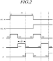
- FIG. 2 illustrates a signal timing chart of a related art sub-pixel transition in the display panel as illustrated in FIG. 1 .
- a control pulse for switching a R sub-pixel driving is applied during a first sub-horizontal period 1 st 1/3H of the horizontal period, and then, control pulses for driving G and B sub-pixels are applied during second and third sub-horizontal periods.
- a rising transition and a falling transition of a control pulse for R sub-pixel driving are denoted as TRU and TRF, respectively, and rising and falling transitions for G and B are also denoted in the same manner (TGU, TGF, TBU, and TBF).
- TGU rising transition and a falling transition of a control pulse for R sub-pixel driving
- Such a transition needs to control the corresponding switching unit. Therefore, as the number of transitions performed to all the colors during the same period (for example, 1 frame, and the like) is increased, complexity of control is increased and power consumption is also increased.
- a method for reducing the number of sub-pixel transitions in the driving method for each color may be provided.
- a method of reducing the number of transitions as compared with a related art method in which two transitions are performed to each color during a horizontal period will be referred to as a "less transition.”
- FIGs. 3A and 3B illustrate an example of a less transition method for reducing the number of transitions for each color.
- a color driven during a last sub-horizontal period of a kth horizontal period H#k is disposed so as to be driven during a first horizontal period of a k+1th horizontal period H#(k+1).
- the overall number of transitions can be reduced.
- FIGs. 3A and 3B illustrate that when sub-pixel colors to be displayed in sequence during one sub-horizontal period are denoted as R, G, and B, the colors are repeatedly displayed in order of RGB, BGR, and RGB. That is, colors driven during a kth horizontal period are disposed in reverse order of colors driven during a previous (k-1)th horizontal period.
- FIG. 3A is a signal timing chart according to the less transition method
- FIG. 3B illustrates colors of an image displayed in sequence.
- the number of transitions to G is a total of four (two rising transitions and two falling transitions), which is equal to the numbers as illustrated in FIG. 1 and FIG. 2 and the number of transition to each of R and B is a total of two (one rising transition and one falling transition), which is a decrease as compared with the numbers as illustrated in FIG. 1 and FIG. 2 .
- FIGs. 3A and 3B a total of two transitions are performed to each of R and B during two horizontal periods and a total of four transitions are performed to G during two horizontal periods, and, thus, G may have image output characteristics different from those of R and B.
- a switching unit for driving each color (sub-pixel) is turned OFF, i.e., if a falling transition is performed, there is a driving voltage change which is referred to as a kick back voltage, and the kick back voltage causes temporary flicker or image sticking.
- an inversion method for inverting the polarity of a driving voltage in each frame may be employed to suppress degradation of a liquid crystal caused by long-time application of a unidirectional electric field to the liquid crystal.
- various inversion methods such as a frame inversion method, a line inversion method, a column inversion method, or a dot inversion method has been applied.
- the column inversion method is a method of changing the polarity in each column (vertical line). In the column inversion method, the polarity of R, G, and B data is inverted.
- a switching unit is switched between -9 V (or 5.2 V) and +9 V (or +5.2 V) and a difference in kick back voltage caused by the above-described falling transition is gradually increased. Therefore, the above-described display defect may be further increased.
- a frame frequency generally indicating the number of frames in one second is 60 Hz to 120 Hz
- display defects may not considerably appear.
- a frame frequency can be lowered to about 30 Hz or less during an operation of outputting a still image or document to reduce power consumption. In this case, flicker or image sticking caused by a difference in number of transitions for each color may cause high display defects.
- FIG. 4 is a plan view of a display panel including a less transition method according to an example embodiment
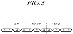
- FIG. 5 illustrates an order of displaying colors according to the less transition method according to an example embodiment.
- a display device configured to perform a new less transition method and includes a display panel including gate lines and data lines and sub-pixels of respective colors defined by intersections between the data lines and the gate lines, a data driver (D-IC) 410 configured to apply a source signal to the data lines, and a transition control unit 420 configured to perform a less transition according to the present exemplary embodiment under the control of the data driver.
- D-IC data driver
- the transition control unit performs a control to sequentially supply a first color sub-pixel, a second color sub-pixel, and a third color sub-pixel with a corresponding source signal during a kth horizontal period and sequentially supply the third color sub-pixel, the first color sub-pixel, and the second color sub-pixel with a corresponding source signal during a k+1th horizontal period.
- a first color is R
- a second color is G
- a third color is B
- R, G, and B sub-pixels are sequentially driven during a first horizontal period and B, R, and G sub-pixels are sequentially driven during a second horizontal period.
- driving is performed in reverse order of the driving performed in a previous horizontal period, whereas in the example embodiment as illustrated in FIG. 3 , a last color of a previous horizontal period is first driven and then the other colors except the last color of the previous horizontal period are sequentially driven.
- an equivalent reduction (33%) of number of transitions compared with the related art transition (of FIG. 1 and FIG. 2 ) can be secured as illustrated in FIG. 3 .
- the same number of transitions is performed to each color.
- the display device further includes a source multiplexer 440 configured to switch the supply of a source signal to each data line.
- the transition control unit performs the above-described less transition by controlling the source multiplexer.
- the source multiplexer includes a plurality of switching elements, S-MUX, connected to each data line.
- the S-MUX may be applied with an S-MUX control signal capable of controlling ON/OFF of the S-MUX.
- the application of S-MUX control signal may be controlled by the data driver D-IC or the transition control unit 420.
- the switching elements are disposed between the data driver (D-IC) 120 and each data line.
- the S-MUX may be configured as a thin film transistor TFT. More specifically, a pixel PIXEL may include three sub-pixels including an R sub-pixel, a G sub-pixel, and a B sub-pixel. The sub-pixels are connected to data lines DL1 to DL3, respectively, and the first gate line GL1.
- a first scan signal is applied to a first gate line during a horizontal period H.
- a first source signal, a second source signal, and a third source signal are applied in sequence to a first data line DL1, a second data line DL2, and a third data line DL3, respectively.
- a horizontal period is divided into three sub-horizontal periods.
- driving may be performed to output the image during a second horizontal period of a k+1th horizontal period H#(k+1)and a third sub-horizontal period of a k+2th horizontal period H#(k+2).
- the transition control unit 420 performs an operation of selectively turning ON one of S-MUX1 to S-MUX3 according to the above-described transition rule.
- the S-MUX structure makes it possible to effectively control a transition according to the present exemplary embodiment.
- a transition driver performs a control to supply an ON pulse to an S-MUX1(R) during the first sub-horizontal period of the kth horizontal period, the second horizontal period of the k+1th horizontal period H#(k+1), and the third sub-horizontal period of the k+2th horizontal period H#(k+2) for R color so as to turn on the S-MUX1, and turn off the S-MUX2(G) and the S-MUX3(B) during that time.
- the color driven in the above-described order is not necessarily R, and G or B may be the color.
- the S-MUX1 is turned ON during the first sub-horizontal period of the kth horizontal period for a specific color (R from among W, R, G, and B)
- driving may be performed to turn ON the S-MUX1 during the second horizontal period of the k+1th horizontal period, the third sub-horizontal period of the k+2th horizontal period, and a fourth sub-horizontal period of a k+3th horizontal period and turn OFF the others S-MUX2(G), S-MUX3(B), and S-MUX4(W).
- the transition control signal may be generated by the data driver 410 or a separate timing controller and then applied.
- the source multiplexer 440 has a concept including all kinds of elements or circuits disposed between the respective data lines and the data driver and configured to switch the application of a source signal from the data driver to the corresponding data line.
- FIG. 4 illustrates that the transition control unit 420 is separate from the data driver 410, the transition control unit 420 may be implemented to be included in the data driver.
- the display panel included in the display device according to the present exemplary embodiment is not limited to a specific type. All kinds of display panels such as a liquid crystal display, an organic light emitting diode (OLED) display device, a plasma display panel, and an electrophoretic display device may be used as long as they include sub-pixels for displaying three or more colors and have transitions for each color.
- OLED organic light emitting diode
- plasma display panel a plasma display panel
- electrophoretic display device may be used as long as they include sub-pixels for displaying three or more colors and have transitions for each color.
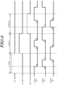
- FIG. 6 illustrates a signal timing chart for implementing a less transition according to an example embodiment.
- the transition control unit 420 applies an ON pulse to the S-MUX1 during a first sub-horizontal period 1 st 1/3H in a state where a gate driving clock GCL #k is applied to a kth gate line during the kth horizontal period H#k, and, thus, supplies a source signal to a total of 3/n number of R sub-pixels. Thereafter, during a second sub-horizontal period 2 nd 1/3H, the transition control unit 420 applies an ON pulse to the S-MUX2(G), and, thus, supplies the source signal to G sub-pixels. Thereafter, during a third sub-horizontal period 3 rd 1/3H, the transition control unit 420 applies an ON pulse to the S-MUX3(B), and, thus, supplies the source signal to B sub-pixels.
- the transition control unit 420 applies an ON pulse to the S-MUX3(B) during a first sub-horizontal period 1 st 1/3H in a state where a gate driving clock GCL #k+1 is applied to a k+1th gate line, and, thus, supplies the source signal to a total of 3/n number of B sub-pixels.
- the B sub-pixels are continuously driven without a transition from the third sub-horizontal period 3 rd 1/3H of the kth horizontal period H#k to the first sub-horizontal period 1 st 1/3H of the k+1th horizontal period H#(k+1).
- the transition control unit 420 supplies an ON pulse to the S-MUX1(R) so as to apply the source signal to R sub-pixels driven during the first sub-horizontal period of the previous horizontal period unlike the less transition, as illustrated in FIG. 3 .
- the transition control unit 420 supplies an ON pulse to the S-MUX2(G) so as to apply the source signal to G sub-pixels driven during the second sub-horizontal period of the previous horizontal period unlike the less transition, as illustrated in FIG. 3 .
- the transition control unit 420 applies an ON pulse to the S-MUX2(G) during a first sub-horizontal period 1 st 1/3H in a state where a gate driving clock GCL #k+2 is applied to a k+2th gate line, and, thus, supplies the source signal to a total of 3/n number of G sub-pixels.
- the G sub-pixels are continuously driven without a transition from the third sub-horizontal period 3 rd 1/3H of the k+1th horizontal period to the first sub-horizontal period 1 st 1/3H of the k+2th horizontal period.
- the transition control unit 420 supplies an ON pulse to the S-MUX3(B) so as to apply the source signal to B sub-pixels driven during the first sub-horizontal period of the previous k+1th horizontal period unlike the less transition, as illustrated in FIG. 3 .
- the transition control unit 420 supplies an ON pulse to the S-MUX1(R) so as to apply the source signal to R sub-pixels driven during the second sub-horizontal period of the k+1th horizontal period unlike the less transition as illustrated in FIG. 3 .
- a total of four transitions i.e., two rising transitions and two falling transitions, are performed to each color during three horizontal periods, as illustrated in FIG. 6 . That is, a total of four transitions are performed to each of three colors in the same manner, and, thus, a total of twelve transitions are performed to all of the colors.
- the number of transitions is reduced by 33%. That is, according to the less transition method of the example embodiment, the reduction of number of transitions equivalent to the reduction (33%) as illustrated in FIG. 3 can be achieved and the same number of transitions is performed to each color unlike the less transition as illustrated in FIG. 3 .
- each color has the same total number of transitions and also has the same number of falling transitions which cause display defects. Therefore, display defects caused by a difference in number of transitions for each color does not occur fundamentally.
- the reduction of number of transitions equivalent to the reduction (33%) as illustrated in FIG. 3 can be achieved and display defects can be suppressed by equalizing the number of transitions for each color.
- FIG. 7 illustrates an order of displaying colors according to a less transition method according to another exemplary embodiment.
- the sub-pixels have three colors R, G, and B.
- the concept of the present disclosure is not limited thereto and can be applied to a display device including sub-pixels of four or more colors in a similar manner.
- RGB organic light emitting diode (OLED) display device all of sub-pixels of three colors R, G, and B may be turned on to express a white color. Therefore, a display panel has low durability with low efficiency, and, thus, may not be suitable for a large-size display panel.
- a so-called WRGB organic light emitting diode display panel further including a white (W) sub-pixel in addition to R, G, and B sub-pixels may be used.
- FIG. 7 illustrates an example embodiment where the sub-pixels have four colors W, R, G, and B.
- the transition control unit may sequentially supply a source signal to a first color, a second color, a third color, and a fourth color during the kth horizontal period H#k. In this case, sub-pixels are driven in order of the fourth color, the first color, the second color, and the third color during the k+1th horizontal period.
- FIG. 7 illustrates an example where the less transition method according to the example embodiment is applied to a display panel in which sub-pixels of four colors are disposed in order of R, G, B, and W.
- the kth horizontal period H#k is divided into four horizontal periods (1/4H) and then driving is performed in order of R, G, B, and W during the respective sub-horizontal periods. Then, during the k+1th horizontal period, driving is performed in order of W, R, G, and B, and during the k+2th horizontal period, driving is performed in order of B, W, R, and G. Then, during the k+3th horizontal period, driving is performed in order of G, B, W, and R. Then, from a subsequent k+4th horizontal period, driving is repeated in the above-described order of the kth to k+3th horizontal periods.
- the example embodiment can be applied to the case where sub-pixels of three or more colors are included, and can reduce the number of transitions and can also suppress display defects caused by a difference in display characteristics of each color by equalizing the number of transitions for each color.
- FIG. 8 illustrates a less transition method according to yet another exemplary embodiment and illustrates an exemplary embodiment in which a different ON pulse width is set for each color.
- widths of ON pulses for respective colors are equal to each other. That is, in the exemplary embodiments illustrated up to FIG. 7 , driving is controlled for each of sub-horizontal periods divided from a horizontal period in the same number as the number of colors.
- a data voltage output to R, G, and B pixels is inverted by the above-described inversion function, holding timing for a green (G) data voltage may be reduced as compared with the other colors. That is, if a transition is performed in a display device driven by the column inversion method, the polarity of a data voltage output to an R sub-pixel, a G sub-pixel, and a B sub-pixel adjacent to each other is changed. Therefore, although the polarity of a data voltage output to the R sub-pixel is the same as the polarity of a data voltage output to the B sub-pixel, the polarity of a data voltage output to the G sub-pixel is opposite to the polarity of the R and B data voltages.
- a period in which a data voltage is actually output during an ON-pulse section for driving the corresponding S-MUX may be shorter in G than in R and B.
- G in the middle of a change between different polarities has a shorter data voltage holding time (source holding time) than an actual input due to a delay caused by rising/falling transitions.
- source holding time the G color more highly affects the luminance than the R and B colors. Therefore, a relatively short holding time of the G color as described above may cause a decrease in luminance.
- an ON-pulse width of an S-MUX controlling G sub-pixels may be set to be greater than an ON-pulse width for controlling R and B sub-pixels.
- an order of sub-pixel transition for each color is the same as that of the exemplary embodiment as illustrated in FIG. 6 , but when setting sub-horizontal periods for each color in a horizontal period, an ON-pulse width PWG of an S-MUX2 control signal for driving G sub-pixels is set to be greater than ON pulse widths PWR and PWB of S-MUX1(R) and S-MUX3(B) for controlling R and B sub-pixels.
- the transition control unit divides the kth horizontal period into three sub-horizontal periods and controls a width of a second sub-horizontal period corresponding to driving of G sub-pixels to be greater than widths of first and third sub-horizontal periods.
- a horizontal period for driving the k+1th gate line is divided in order for a third sub-horizontal period corresponding to driving of G sub-pixels to be greater than first and second sub-horizontal periods.
- the transition control unit according to the example embodiment as illustrated in FIG. 8 separately performs an operation of controlling an order of transitions and an operation of controlling a sub-horizontal period corresponding to driving of G sub-pixels to be greater than sub-horizontal periods for R and B sub-pixels in each horizontal period at the same time.
- a data voltage holding time of G sub-pixels can be adjusted to be equivalent to those of R and B sub-pixels, and, thus, the luminance can be maintained in an inversion-type display device.
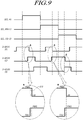
- FIG. 9 illustrates a less transition method according to still another example embodiment and illustrates a configuration in which ON pulses of respective colors are partially overlapped.
- the insufficient charging time may become a more sensitive issue due to a delay of a switching element occurring during a transition.
- ON pulses for driving the S-MUX for transition control are partially overlapped to partly improve such deterioration of image quality.
- the transition control unit controls ON pulse of two colors in transition to be partially overlapped. For example, during a R-G transition process as a first transition in the kth horizontal period, the transition control unit controls a rising transition TGU of the S-MUX2(G) to occur before the occurrence of a falling transition TRF of the S-MUX1(R).
- the G color most affects the luminance due to a reduction in holding time caused by inversion of a data voltage. Therefore, ON pulse widths can be controlled to be partially overlapped in a transition related to the G color.
- sub-horizontal periods are equally divided and ON pulses for R and B colors are synchronized with the divided sub-horizontal periods, and a start timing of a rising transition TGU of the G color may be controlled to occur before the occurrence of a falling transition TRF of the R color and a falling transition TGF of the G color may be controlled to occur before the occurrence of a rising transition TBU of the B color.
- a decrease in luminance of the G color occurring in the inversion method can be reduced without an additional control to asymmetrically divide sub-horizontal periods.
- FIG. 10 illustrates a less transition method according to a modification of the example of FIG. 9 and illustrates a configuration in which S-MUX ON pulses of respective colors are partially overlapped and ON periods of source signals for the respective colors are adjusted to suppress color mixing.
- ON periods of S-MUXs are set to be partially overlapped to secure a charging time, there may be mixing of colors.
- ON periods of S-MUXs are set to be partially overlapped for each color so as to secure a charging time, but ON periods of source signals for the respective colors during sub-horizontal periods are set not to be overlapped with each other. Thus, color mixing can be suppressed.
- FIG. 10 illustrates that ON periods of S-MUXs are set to be partially overlapped during a period of a transition to the G color but ON periods (indicated by a dotted line in FIG. 10 ) of source signals for the R and B colors are set not to be overlapped with an ON period of a source signal for the G color to suppress a decrease in luminance of the G color and color mixing. That is, as illustrated in the enlarged areas A and B of FIG. 10 , in a transition from R to G, an R source signal (dotted line) is controlled to be turned OFF before the occurrence of a falling transition of the S-MUX for the R color, and, thus, color mixing with the G signal can be suppressed. Meanwhile, it should be understood that although not illustrated in the drawing, a transition control method configured as described below is also included in the present specification.
- a transition control method is performed by a display device including a first color sub-pixel, a second color sub-pixel, and a third color sub-pixel and a transition control unit configured to control a transition for each color.
- the transition control method includes repeatedly performing a first step in which a kth horizontal period is time-divided into three sub-horizontal periods, and then, a first color sub-pixel is driven during a first sub-horizontal period, a second color sub-pixel is driven during a second sub-horizontal period, and a third color sub-pixel is driven during a third sub-horizontal period and a second step in which a subsequent k+1th horizontal period is time-divided into three sub-horizontal periods, and then, the third color sub-pixel is driven during a first sub-horizontal period, the first color sub-pixel is driven during a second sub-horizontal period, and the second color sub-pixel is driven during a third sub-horizontal period.
- the number of transitions can be reduced as compared with the related art transition method, and the numbers of sub-pixel transitions for respective colors are equalized to each other. Thus, it is possible to suppress display defects caused by a sub-pixel transition.
- the sub-pixel transition when a sub-pixel transition is performed to a first color, a second color, and a third color in sequence during a kth horizontal period, the sub-pixel transition is performed to the third color, the first color, and the second color in sequence during a k+1th horizontal period.
- the overall number of transitions can be reduced and the numbers of sub-pixel transitions for the respective colors can be equal to each other. Therefore, it is possible to maintain excellent image output characteristics.
- an ON-pulse width of an S-MUX controlling a G color sub-pixel may be controlled to be greater than an ON-pulse width for controlling R and B color sub-pixels.
- a number of transitions between sub-pixels is reduced.
- the numbers of sub-pixel transitions for respective colors are equalized to each other.
- a sub-pixel transition when a sub-pixel transition is performed to a first color, a second color, and a third color in sequence during a kth horizontal period, a sub-pixel transition is performed to the third color, the first color, and the second color in sequence during a k+1th horizontal period.
- the overall number of transitions can be reduced and the numbers of sub-pixel transitions for the respective colors can be equal to each other.
- S-MUX source multiplexer
- the S-MUX is controlled to perform a sub-pixel transition to the third color, the first color, and the second color in sequence during a k+1th horizontal period.
Landscapes
- Engineering & Computer Science (AREA)
- Physics & Mathematics (AREA)
- Computer Hardware Design (AREA)
- General Physics & Mathematics (AREA)
- Theoretical Computer Science (AREA)
- Chemical & Material Sciences (AREA)
- Crystallography & Structural Chemistry (AREA)
- Control Of Indicators Other Than Cathode Ray Tubes (AREA)
- Liquid Crystal Display Device Control (AREA)
- Electroluminescent Light Sources (AREA)
- Liquid Crystal (AREA)
Applications Claiming Priority (1)
| Application Number | Priority Date | Filing Date | Title |
|---|---|---|---|
| KR1020160125354A KR102509164B1 (ko) | 2016-09-29 | 2016-09-29 | 표시장치 및 그를 이용한 서브픽셀 트랜지션 방법 |
Publications (2)
| Publication Number | Publication Date |
|---|---|
| EP3301669A2 true EP3301669A2 (fr) | 2018-04-04 |
| EP3301669A3 EP3301669A3 (fr) | 2018-05-23 |
Family
ID=59997282
Family Applications (1)
| Application Number | Title | Priority Date | Filing Date |
|---|---|---|---|
| EP17194155.2A Ceased EP3301669A3 (fr) | 2016-09-29 | 2017-09-29 | Dispositif d'affichage et procédé de transition de sous-pixels |
Country Status (6)
| Country | Link |
|---|---|
| US (1) | US10467941B2 (fr) |
| EP (1) | EP3301669A3 (fr) |
| JP (1) | JP6469798B2 (fr) |
| KR (1) | KR102509164B1 (fr) |
| CN (1) | CN107886885A (fr) |
| TW (1) | TWI635471B (fr) |
Families Citing this family (12)
| Publication number | Priority date | Publication date | Assignee | Title |
|---|---|---|---|---|
| US10748495B2 (en) * | 2018-04-12 | 2020-08-18 | Wuhan China Star Optoelectronics Technology Co., Ltd. | Pixel driving circuit and liquid crystal display circuit with the same |
| CN110400538B (zh) * | 2018-04-19 | 2021-02-09 | 群创光电股份有限公司 | 电子装置 |
| KR102563109B1 (ko) * | 2018-09-04 | 2023-08-02 | 엘지디스플레이 주식회사 | 디스플레이 장치 |
| CN111105761B (zh) * | 2018-10-29 | 2022-04-22 | 北京小米移动软件有限公司 | 显示面板及其控制方法、显示装置 |
| US10984697B2 (en) * | 2019-01-31 | 2021-04-20 | Novatek Microelectronics Corp. | Driving apparatus of display panel and operation method thereof |
| US11594200B2 (en) * | 2019-01-31 | 2023-02-28 | Novatek Microelectronics Corp. | Driving apparatus of display panel and operation method thereof |
| CN109817150A (zh) * | 2019-03-28 | 2019-05-28 | 京东方科技集团股份有限公司 | 一种像素驱动方法、像素驱动装置及显示装置 |
| CN112216219A (zh) * | 2019-07-09 | 2021-01-12 | 成都辰显光电有限公司 | 像素排布结构、显示面板和显示装置 |
| KR102747274B1 (ko) | 2019-12-27 | 2024-12-26 | 엘지디스플레이 주식회사 | 표시 장치 |
| CN111477180B (zh) * | 2020-04-21 | 2024-04-12 | 京东方科技集团股份有限公司 | 一种显示面板及其驱动方法、显示装置 |
| CN112289268A (zh) | 2020-11-02 | 2021-01-29 | 武汉华星光电技术有限公司 | 显示面板的驱动方法及装置 |
| JP2024160562A (ja) * | 2023-05-01 | 2024-11-14 | 株式会社ジャパンディスプレイ | エレクトロクロミックデバイス |
Citations (2)
| Publication number | Priority date | Publication date | Assignee | Title |
|---|---|---|---|---|
| US20040017341A1 (en) * | 2002-06-10 | 2004-01-29 | Katsuhiko Maki | Drive circuit, electro-optical device and driving method thereof |
| US20040150599A1 (en) * | 2002-11-21 | 2004-08-05 | Seiko Epson Corporation | Driver circuit, electro-optical device, and drive method |
Family Cites Families (51)
| Publication number | Priority date | Publication date | Assignee | Title |
|---|---|---|---|---|
| JP2003167556A (ja) | 2001-11-29 | 2003-06-13 | Hitachi Ltd | マトリックス型表示装置、その駆動制御装置及び駆動制御方法 |
| JP5027976B2 (ja) | 2002-07-15 | 2012-09-19 | セイコーエプソン株式会社 | 電気光学装置、電子機器及び電気光学装置の駆動方法 |
| TW567678B (en) * | 2002-10-08 | 2003-12-21 | Ind Tech Res Inst | Driving system for Gamma correction |
| JP4694134B2 (ja) * | 2004-03-09 | 2011-06-08 | 株式会社 日立ディスプレイズ | 表示装置 |
| JP4049162B2 (ja) * | 2004-06-18 | 2008-02-20 | セイコーエプソン株式会社 | 電気光学装置及び電子機器 |
| JP2006119581A (ja) * | 2004-09-24 | 2006-05-11 | Koninkl Philips Electronics Nv | アクティブマトリクス型液晶表示装置およびその駆動方法 |
| US7764255B2 (en) * | 2005-02-09 | 2010-07-27 | Himax Technologies Limited | Liquid crystal on silicon (LCOS) display driving system and the method thereof |
| TWI275056B (en) * | 2005-04-18 | 2007-03-01 | Wintek Corp | Data multiplex circuit and its control method |
| JP2007010946A (ja) | 2005-06-30 | 2007-01-18 | Seiko Epson Corp | 電気光学装置、駆動方法および電子機器 |
| CN101331535A (zh) * | 2005-12-16 | 2008-12-24 | Nxp股份有限公司 | 用于显示器中色彩偏移补偿的设备和方法 |
| US7834868B2 (en) | 2006-02-01 | 2010-11-16 | Tpo Displays Corp. | Systems for displaying images and control methods thereof |
| US7633495B2 (en) * | 2006-02-14 | 2009-12-15 | Tpo Displays Corp. | Driving circuit with low power consumption multiplexer and a display panel and an electronic device using the same |
| JP2008046485A (ja) * | 2006-08-18 | 2008-02-28 | Nec Electronics Corp | 表示装置、表示パネルの駆動装置、及び表示装置の駆動方法 |
| JP2008122517A (ja) | 2006-11-09 | 2008-05-29 | Eastman Kodak Co | データドライバおよび表示装置 |
| KR100896045B1 (ko) | 2007-06-26 | 2009-05-11 | 엘지전자 주식회사 | 유기전계발광표시장치 |
| TW200915281A (en) * | 2007-09-27 | 2009-04-01 | Chunghwa Picture Tubes Ltd | Driving circuit and related driving method of a display panel |
| TWI377555B (en) * | 2007-11-15 | 2012-11-21 | Tpo Displays Corp | Electronic device, dual view display and the signal compensating apparatus and method thereof |
| JP2009139774A (ja) * | 2007-12-10 | 2009-06-25 | Hitachi Displays Ltd | 表示装置 |
| TWI387956B (zh) * | 2008-03-12 | 2013-03-01 | Au Optronics Corp | 實現點反轉的資料多工器架構之液晶顯示裝置及其驅動方法 |
| TW200945310A (en) * | 2008-04-29 | 2009-11-01 | Au Optronics Corp | Driving unit |
| JP5657198B2 (ja) * | 2008-08-07 | 2015-01-21 | グローバル・オーエルイーディー・テクノロジー・リミテッド・ライアビリティ・カンパニーGlobal Oled Technology Llc. | 表示装置 |
| US20100182295A1 (en) * | 2009-01-20 | 2010-07-22 | Chen Ping-Po | Lcd driving circuit and driving method thereof |
| US20100182333A1 (en) * | 2009-01-22 | 2010-07-22 | Shao-Yang Chiang | Color Deviation Compensating Method and Driving Device for an LCD Panel and Related LCD Device |
| CN102376281A (zh) | 2010-08-23 | 2012-03-14 | 联咏科技股份有限公司 | 驱动模块与驱动方法 |
| US8502842B2 (en) * | 2011-05-24 | 2013-08-06 | Apple Inc. | Offsetting multiple coupling effects in display screens |
| US8648845B2 (en) * | 2011-05-24 | 2014-02-11 | Apple Inc. | Writing data to sub-pixels using different write sequences |
| US20130076720A1 (en) * | 2011-09-23 | 2013-03-28 | Ahmad Al-Dahle | Pixel guard lines and multi-gate line configuration |
| WO2013054724A1 (fr) * | 2011-10-11 | 2013-04-18 | シャープ株式会社 | Dispositif d'affichage et procédé d'alimentation de celui-ci |
| KR101985247B1 (ko) | 2011-12-02 | 2019-06-04 | 엘지디스플레이 주식회사 | 액정표시장치와 그 구동 방법 |
| TWI447693B (zh) | 2011-12-07 | 2014-08-01 | Orise Technology Co Ltd | 用於三角式排列顯示面板之像素資料轉換方法及裝置 |
| TWI473061B (zh) * | 2012-10-22 | 2015-02-11 | Au Optronics Corp | 電致發光顯示面板及其驅動方法 |
| KR102007775B1 (ko) * | 2013-01-31 | 2019-10-21 | 엘지디스플레이 주식회사 | 액정표시장치 및 그 구동방법 |
| TWI496130B (zh) * | 2013-03-13 | 2015-08-11 | Au Optronics Corp | 顯示器及其中之信號傳送方法 |
| TWI492212B (zh) | 2013-05-07 | 2015-07-11 | Au Optronics Corp | 驅動裝置及驅動方法 |
| KR102098743B1 (ko) * | 2013-10-02 | 2020-04-09 | 삼성디스플레이 주식회사 | 유기 발광 표시 패널 |
| JP2015079138A (ja) | 2013-10-17 | 2015-04-23 | セイコーエプソン株式会社 | 電気光学装置、電気光学装置の駆動方法及び電子機器 |
| KR102122529B1 (ko) * | 2013-12-10 | 2020-06-12 | 엘지디스플레이 주식회사 | 표시장치용 구동회로 |
| KR102254623B1 (ko) * | 2013-12-13 | 2021-05-24 | 삼성디스플레이 주식회사 | 유기 발광 표시 장치 |
| KR102137079B1 (ko) * | 2014-03-03 | 2020-07-24 | 삼성디스플레이 주식회사 | 유기 발광 표시 장치 |
| TWI539432B (zh) | 2014-07-07 | 2016-06-21 | 友達光電股份有限公司 | 畫素電路及其控制方法與具該電路的顯示裝置 |
| TWI543056B (zh) * | 2014-08-14 | 2016-07-21 | 群創光電股份有限公司 | 顯示裝置及觸控顯示裝置 |
| TWI529695B (zh) | 2014-09-15 | 2016-04-11 | 友達光電股份有限公司 | 顯示面板及其中之信號傳送方法 |
| US20160093260A1 (en) * | 2014-09-29 | 2016-03-31 | Innolux Corporation | Display device and associated method |
| CN105632387B (zh) * | 2014-11-05 | 2018-11-27 | 群创光电股份有限公司 | 显示装置 |
| CN104751766B (zh) * | 2015-04-08 | 2017-08-29 | 京东方科技集团股份有限公司 | 一种显示面板、其驱动方法及显示装置 |
| CN104991389A (zh) * | 2015-07-16 | 2015-10-21 | 武汉华星光电技术有限公司 | 显示面板及其驱动方法 |
| US20170017325A1 (en) * | 2015-07-17 | 2017-01-19 | Innolux Corporation | Touch display device |
| CN105118431A (zh) * | 2015-08-31 | 2015-12-02 | 上海和辉光电有限公司 | 像素驱动电路及其驱动方法和显示装置 |
| CN107492351B (zh) * | 2016-06-13 | 2019-12-10 | 上海和辉光电有限公司 | 显示装置、像素驱动电路及其驱动方法 |
| CN106205555A (zh) * | 2016-08-30 | 2016-12-07 | 武汉华星光电技术有限公司 | 显示装置及其亮度调整方法 |
| CN106448584B (zh) * | 2016-08-31 | 2018-12-18 | 深圳市华星光电技术有限公司 | 一种四色面板的过驱动方法 |
-
2016
- 2016-09-29 KR KR1020160125354A patent/KR102509164B1/ko active Active
-
2017
- 2017-08-24 US US15/685,421 patent/US10467941B2/en active Active
- 2017-09-13 TW TW106131375A patent/TWI635471B/zh active
- 2017-09-28 CN CN201710899321.3A patent/CN107886885A/zh active Pending
- 2017-09-29 EP EP17194155.2A patent/EP3301669A3/fr not_active Ceased
- 2017-09-29 JP JP2017190528A patent/JP6469798B2/ja active Active
Patent Citations (2)
| Publication number | Priority date | Publication date | Assignee | Title |
|---|---|---|---|---|
| US20040017341A1 (en) * | 2002-06-10 | 2004-01-29 | Katsuhiko Maki | Drive circuit, electro-optical device and driving method thereof |
| US20040150599A1 (en) * | 2002-11-21 | 2004-08-05 | Seiko Epson Corporation | Driver circuit, electro-optical device, and drive method |
Also Published As
| Publication number | Publication date |
|---|---|
| JP6469798B2 (ja) | 2019-02-13 |
| US10467941B2 (en) | 2019-11-05 |
| US20180090046A1 (en) | 2018-03-29 |
| JP2018055100A (ja) | 2018-04-05 |
| EP3301669A3 (fr) | 2018-05-23 |
| CN107886885A (zh) | 2018-04-06 |
| KR102509164B1 (ko) | 2023-03-13 |
| KR20180035963A (ko) | 2018-04-09 |
| TW201814680A (zh) | 2018-04-16 |
| TWI635471B (zh) | 2018-09-11 |
Similar Documents
| Publication | Publication Date | Title |
|---|---|---|
| US10467941B2 (en) | Display device and method of sub-pixel transition | |
| US8451206B2 (en) | Liquid crystal display and method with field sequential driving and frame polarity reversal | |
| JP5414974B2 (ja) | 液晶表示装置 | |
| US20100315402A1 (en) | Display panel driving method, gate driver, and display apparatus | |
| US8232932B2 (en) | Display device | |
| CN100527208C (zh) | 液晶显示器及其驱动方法 | |
| WO2018094803A1 (fr) | Procédé de pilotage d'un panneau d'affichage à quatre couleurs primaires rvbb | |
| JP2016539365A (ja) | 液晶パネルの駆動回路、駆動方法及び液晶表示装置 | |
| WO2014000384A1 (fr) | Panneau d'affichage ainsi que procédé de commande et dispositif d'affichage associés | |
| US8669927B2 (en) | Liquid crystal display device and driving method thereof | |
| US10942405B2 (en) | Display device | |
| US9595233B2 (en) | Display device and driving method thereof | |
| JP2009251608A (ja) | 液晶ディスプレイモジュール及び液晶ディスプレイ駆動方法 | |
| TWI416497B (zh) | 液晶顯示裝置之驅動方法及其相關裝置 | |
| TWI657423B (zh) | 時序控制器與顯示面板驅動器的溫度管理方法 | |
| KR100542769B1 (ko) | 액정표시장치 및 그 구동방법 | |
| KR100853771B1 (ko) | 액정표시장치 | |
| KR20110107585A (ko) | 액정 표시장치 및 구동방법 | |
| KR20180007456A (ko) | 표시 장치 | |
| KR20030056350A (ko) | 액정표시패널과 그의 구동장치 및 구동방법 | |
| JP2006030835A (ja) | アレイ基板、液晶ディスプレイおよびそれらの駆動方法 | |
| KR20130051740A (ko) | 액정표시장치 및 그 구동방법 | |
| KR101192800B1 (ko) | 액정표시장치 및 이의 구동방법 | |
| KR102560740B1 (ko) | 액정표시장치 | |
| KR20170124870A (ko) | 표시장치 및 이의 동작방법 |
Legal Events
| Date | Code | Title | Description |
|---|---|---|---|
| PUAI | Public reference made under article 153(3) epc to a published international application that has entered the european phase |
Free format text: ORIGINAL CODE: 0009012 |
|
| 17P | Request for examination filed |
Effective date: 20170929 |
|
| AK | Designated contracting states |
Kind code of ref document: A2 Designated state(s): AL AT BE BG CH CY CZ DE DK EE ES FI FR GB GR HR HU IE IS IT LI LT LU LV MC MK MT NL NO PL PT RO RS SE SI SK SM TR |
|
| AX | Request for extension of the european patent |
Extension state: BA ME |
|
| PUAL | Search report despatched |
Free format text: ORIGINAL CODE: 0009013 |
|
| AK | Designated contracting states |
Kind code of ref document: A3 Designated state(s): AL AT BE BG CH CY CZ DE DK EE ES FI FR GB GR HR HU IE IS IT LI LT LU LV MC MK MT NL NO PL PT RO RS SE SI SK SM TR |
|
| AX | Request for extension of the european patent |
Extension state: BA ME |
|
| RIC1 | Information provided on ipc code assigned before grant |
Ipc: G09G 3/20 20060101ALI20180417BHEP Ipc: G09G 3/3208 20160101ALN20180417BHEP Ipc: G09G 3/36 20060101AFI20180417BHEP |
|
| RBV | Designated contracting states (corrected) |
Designated state(s): AL AT BE BG CH CY CZ DE DK EE ES FI FR GB GR HR HU IE IS IT LI LT LU LV MC MK MT NL NO PL PT RO RS SE SI SK SM TR |
|
| 17Q | First examination report despatched |
Effective date: 20181220 |
|
| STAA | Information on the status of an ep patent application or granted ep patent |
Free format text: STATUS: THE APPLICATION HAS BEEN REFUSED |
|
| 18R | Application refused |
Effective date: 20191223 |