EP3301694A1 - Refroidissement de composants inductifs - Google Patents
Refroidissement de composants inductifs Download PDFInfo
- Publication number
- EP3301694A1 EP3301694A1 EP16191437.9A EP16191437A EP3301694A1 EP 3301694 A1 EP3301694 A1 EP 3301694A1 EP 16191437 A EP16191437 A EP 16191437A EP 3301694 A1 EP3301694 A1 EP 3301694A1
- Authority
- EP
- European Patent Office
- Prior art keywords
- iron core
- packages
- iron
- cooling
- sub
- Prior art date
- Legal status (The legal status is an assumption and is not a legal conclusion. Google has not performed a legal analysis and makes no representation as to the accuracy of the status listed.)
- Withdrawn
Links
- 238000001816 cooling Methods 0.000 title claims abstract description 57
- 230000001939 inductive effect Effects 0.000 title claims abstract description 12
- XEEYBQQBJWHFJM-UHFFFAOYSA-N Iron Chemical group [Fe] XEEYBQQBJWHFJM-UHFFFAOYSA-N 0.000 claims abstract description 147
- 239000002826 coolant Substances 0.000 claims abstract description 47
- 238000004804 winding Methods 0.000 claims abstract description 45
- 229910052742 iron Inorganic materials 0.000 claims abstract description 38
- 238000000034 method Methods 0.000 claims abstract description 6
- 125000006850 spacer group Chemical group 0.000 claims description 24
- 239000007788 liquid Substances 0.000 claims description 9
- 230000000694 effects Effects 0.000 abstract description 8
- 210000002414 leg Anatomy 0.000 description 25
- 230000005291 magnetic effect Effects 0.000 description 11
- 230000004907 flux Effects 0.000 description 6
- 230000001965 increasing effect Effects 0.000 description 5
- 239000010410 layer Substances 0.000 description 5
- 238000005452 bending Methods 0.000 description 4
- 238000010276 construction Methods 0.000 description 2
- 239000000110 cooling liquid Substances 0.000 description 2
- 239000000853 adhesive Substances 0.000 description 1
- 230000001070 adhesive effect Effects 0.000 description 1
- 230000015572 biosynthetic process Effects 0.000 description 1
- 239000004020 conductor Substances 0.000 description 1
- 230000007423 decrease Effects 0.000 description 1
- 230000001419 dependent effect Effects 0.000 description 1
- 238000010292 electrical insulation Methods 0.000 description 1
- 230000005294 ferromagnetic effect Effects 0.000 description 1
- 238000012423 maintenance Methods 0.000 description 1
- 238000004519 manufacturing process Methods 0.000 description 1
- 239000000463 material Substances 0.000 description 1
- 239000002184 metal Substances 0.000 description 1
- 229910052751 metal Inorganic materials 0.000 description 1
- 230000008092 positive effect Effects 0.000 description 1
- 239000002356 single layer Substances 0.000 description 1
- 230000006641 stabilisation Effects 0.000 description 1
- 238000011105 stabilization Methods 0.000 description 1
- 230000002123 temporal effect Effects 0.000 description 1
- 210000000689 upper leg Anatomy 0.000 description 1
- 229910000859 α-Fe Inorganic materials 0.000 description 1
Images



Classifications
-
- H—ELECTRICITY
- H01—ELECTRIC ELEMENTS
- H01F—MAGNETS; INDUCTANCES; TRANSFORMERS; SELECTION OF MATERIALS FOR THEIR MAGNETIC PROPERTIES
- H01F27/00—Details of transformers or inductances, in general
- H01F27/08—Cooling; Ventilating
-
- H—ELECTRICITY
- H01—ELECTRIC ELEMENTS
- H01F—MAGNETS; INDUCTANCES; TRANSFORMERS; SELECTION OF MATERIALS FOR THEIR MAGNETIC PROPERTIES
- H01F27/00—Details of transformers or inductances, in general
- H01F27/28—Coils; Windings; Conductive connections
- H01F27/2876—Cooling
Definitions
- the invention relates to an iron core for an inductive component, wherein the iron core comprises a plurality of iron sheets arranged in parallel, wherein the iron core is wrapped at least in sections with at least one winding.
- the invention further relates to a reactor, a transformer and a pulse inverter with such an iron core. Furthermore, the invention relates to a method for cooling such an iron core.
- Inductive components also referred to as inductors.
- the group of these devices includes devices that generate a magnetic flux.
- a large number of these components conduct this magnetic flux in an iron core.
- the iron core is made of a magnetically highly conductive material such as a ferrite.
- the iron core often includes yokes and thighs.
- windings are placed around the iron core. With the help of the magnetic field, i. the magnetic flux, it is also possible to exchange energy between different windings or even parts of windings. For example, transformers use this principle.
- Inductors are needed in particular when voltage sources with different instantaneous values are to be electrically connected. This is true, for example, if, with the aid of pulse-controlled inverters, also referred to as power converters, power is to be obtained from a power supply network or fed into this network.
- Pulse inverters generate approximately rectangular voltages, in which only the temporal mean value can be continuously adjusted, while the mains voltage is continuous (usually approximately sinusoidal).
- inductance usually chokes are used, which have one or more current-carrying windings on a ferromagnetic core.
- the invention has for its object to improve an inductive component with respect to its cooling.
- an iron core for an inductive component wherein the iron core comprises a plurality of iron sheets arranged in parallel, wherein the iron core is at least partially wrapped with at least one winding, wherein the iron sheets are arranged in at least two sub-packages, wherein the iron sheets of the respective Partial packages are arranged in layers, wherein the different sub-packages have a distance from one another, wherein a gap between the sub-packages is formed by the distance, wherein the intermediate space can be flowed through by a coolant.
- the object is achieved by a choke or a transformer with such an iron core.
- the object is achieved by pulse inverters with such an iron core or with such a choke or with such a transformer, wherein the power converter has a means for generating a coolant flow, in particular a fan or a coolant pump. Furthermore, the object is achieved by a method for cooling such an iron core or such a throttle or such a transformer, wherein by means of a means for generating a flow of coolant, in particular by means of a fan or a coolant pump, a flow of the coolant is generated in the intermediate space.
- the invention is based on the finding that the cooling of an inductive component can be improved by changing the iron core.
- a main aspect is to give the magnetic circuit formed by the iron core, an inductive component, a larger surface area, so that the losses incurred in the volume can be more easily delivered to a coolant.
- the invention affects with increasing size of inductive components, because otherwise the power loss increases with the volume stronger than the surface for delivering this power loss to a coolant.
- the laminated core of the iron core is divided into several sub-packages.
- the subpackets are arranged at a distance to each other.
- the gap formed by the gap or the spaces formed between the sub-packages are flowed through by coolant.
- coolant may be a gaseous cooling medium such as air, which is caused by a fan in flow.
- a cooling liquid can also be used as the coolant, which is circulated by means of a coolant pump into circulation and thus into a flow.
- the coolant can flow directly along the sub-packages or it can be a cooling body, in particular a liquid cooling body or an air cooling body, are arranged between the sub-packages.
- the improved cooling enables higher flux densities (i.e., currents) and / or frequencies in the winding. Not only the losses of the core can be better dissipated, also the losses of the winding can be given by the existing interstices in the core better to the cooling medium. This results in a better cooling, which allows a higher load at the same temperature by larger currents or higher frequencies.
- the path between the hottest point inside the subpacket and its surface becomes shorter. This reduces the maximum occurring temperature within the iron core. Likewise, at a given maximum temperature in the iron core, a higher temperature can be achieved at the surface of the sub-package. With this higher temperature, the heat can be better delivered to the cooling medium. The cooling effect increases with it and it can be higher currents and / or frequencies in the winding achieve. Likewise, this high electrical performance can be realized with a small size and low weight.
- a cooling body in particular a liquid cooling body, is arranged in the intermediate space.
- the heat sink may be configured to further increase the effective surface area. In the case of a heat sink for the cooling medium air, this can be done for example by cooling fins. Thus, the cooling capacity can be further increased.
- a liquid heat sink is possible. With this and other connecting parts such as hoses a defined coolant circuit is generated.
- the cooling liquid can circulate, for example, circulated by a pump and receive heat from the iron core and / or the winding and deliver it to the environment, for example by means of a heat exchanger. Also by this configuration, the electrical conductivity of the core and thus also the corresponding throttle or the transformer can be further increased.
- spacers are arranged between the sub-packages. These spacers ensure that the gap is maintained over the life and does not change. In addition, the spacers give the structure of the iron core high stability.
- the spacer is formed by an insulating strip, a welded U-profile or a spacer pin. These embodiments of the spacer have proven to be particularly inexpensive and / or durable.
- the spacer is formed by a further sheet iron, wherein the further iron sheet is identical to one of the iron plates arranged in parallel, wherein the further iron sheet at least in sections has an upstand.
- the spacer can be used as a spacer the same sheet iron as it comes with the sub-packages used.
- a particular advantage is that this has the same magnetic and thermal properties as the iron sheets of the sub-packages. Therefore, the spacer contributes to guiding the magnetic flux. Due to the same thermal properties, stresses due to different temperature expansions are avoided.
- the bends are preferably formed by bending the edges of the iron sheet in the vicinity of the legs. These Aufkantonne can extend over parts of the outer edge or over the full length of the iron sheet.
- the iron core on three legs Inductive components for connection to a three-phase power supply network or to a three-phase network often have three legs.
- the three legs are usually arranged not only parallel but also in a plane. This results in a conventional construction for the middle leg compared to the outer legs thermally significant unfavorable conditions. This applies to both the cooling, ie cooling, of the iron core as well as the winding. Due to the new structure, the thermal properties of all three legs can be adapted to each other by the spaces between the individual sub-packages such that the same, at least almost the same, thermal conditions are present. Thus, the middle leg is not heated much more in operation than the outside.
- FIG. 1 and the FIG. 2 each show a structure of an already known throttle 7 with three legs 9, to which windings 8 are mounted.
- a throttle 7 with three legs 9 is also referred to as a three-arm throttle.
- the three legs 9 would be constructed identically, only for reasons of clarity, the different methods for cooling at a throttle 7 are shown here in only one figure. It shows the FIG. 1 a front view of the throttle 7, while the FIG. 2 the throttle in a section through the plane II of FIG. 1 represents.
- the throttle 7 essentially comprises the magnetic circuit, which is also referred to as the core or iron core 1, and the windings 8.
- the iron core 1 comprises legs 9 and yokes 10 which connect the legs 9 to one another.
- a closed magnetic circuit can form through the legs 9 via the yokes 10.
- the winding 8 can enclose the core without clearance (left leg 9), be applied at a distance from the core (middle leg 9), which are realized for example by winding spacers 30, or in multiple layers with intermediate cooling channels be divided (right leg 9), with additional winding spacers 30 between the individual windings 8 for stabilization can be used here.
- the coolable surface of the winding 8 increases from left to right. This increases the capacity of the winding to release power loss in the form of heat to the environment. Since the right-hand winding can be better penetrated by the cooling medium, more arrows are shown here.
- the iron core 1 can deliver losses through the yokes 10 and through the winding 8 therethrough, provided that the winding is applied to the iron core (left leg 9), via the yokes 10 and the uncovered surfaces of the iron core 1 under the winding 8 (middle and right leg 9).
- the remaining surfaces are shaded by the yokes 10 and are therefore only partially suitable for cooling.
- the leg 9 shown in the middle therefore has only the two in FIG. 2 horizontally displayed free surfaces under the winding, which are not shaded by the yokes and thus better suited for cooling than those in FIG. 2 perpendicular surfaces of the iron core 1, which are shadowed by the yokes. These horizontal surfaces are thus suitable in particular for the cooling of iron core 1 and / or winding 8.
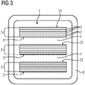
- FIG. 3 shows a section through an iron core 1, which has three sub-packages 3.
- the entire iron core 1 including the yokes 10 is divided into these three sub-packages 3.
- the representation of the yoke 10 has been omitted for reasons of clarity.
- To recognize are also the individual iron sheets 2, each layered a sub-package 3 form. Between the sub-packages 3 is a gap 4, through which the cooling medium, in particular air, can flow.
- three sub-packages 3 are present.
- the number of sub-packages 3 can be chosen arbitrarily, for example as a function of the power loss of the core or of the winding.
- To the iron core 1 around a winding 8 is arranged.
- This illustration shows only one leg 9 and applies analogously to possible further legs of a closed iron core 1.
- the cooling medium in particular cooling air, flows in the cross-sectional view in an advantageous manner perpendicular to the plane of the drawing. Since the yokes 10 are divided into sub-packages 3, the surface 31 which is particularly effective for cooling is increased in comparison to an arrangement without individual sub-packages 3. In this case, a division of the winding 8 in separately cooled layers is possible. For the sake of clarity, no winding spacers 30 are shown in this figure, although these can have a positive effect on the stability of the structure. While in a core of the prior art, the coolable surface results from the circumference of the core, the effective for the cooling surface 31 increases by the division of the core 1 on sub-packages. 3
- FIG. 4 shows the iron core 1 in a perspective view, in which no distance between individual sub-packages 3 exists.
- the centers of the side surfaces of the core are poorly ventilated and thus insufficiently cooled (hatched areas shown).
- the cooling medium in particular air, can pass between the sub-packages 3 and cool both the iron core 1 and the windings 8, not shown here.
- the cooling medium in particular air, can pass between the sub-packages 3 and cool both the iron core 1 and the windings 8, not shown here.
- the cooling medium in particular air
- FIG. 6 shows the section through the embodiment of a three-armature choke.
- the representation of the yoke 10 has been omitted for reasons of clarity.
- This has a flow region 33 (dash-dotted outline) in which a satisfactory cooling effect can be achieved by the flowing cooling medium.
- FIG. 7 explained.
- the winding spacers 30 are arranged in the winding 8 where they are in coincidence with the sub-package 3 of the iron core 1.
- the coolant passage is the least obstructed, especially in the region of the interstices 4, which continues through the winding 8.
- FIG. 7 is unlike the Figures 3 and 6 also shown the yoke 10. To avoid repetition, reference is made to the description of these figures and to the reference numerals introduced there.
- the winding 8 can be as in FIG. 3 (single-layer winding) or as in FIG. 6 (multilayer / double-layer winding) be executed. It is clear from this figure that the division of the iron core 1 into subpackets 3 also continues via the yoke 10 and also brings advantages in the region of the yokes 10. Through the spaces in the region of the yoke 10, the cooling air can flow through better, so that even in the region of the legs 9 a better cooling effect can be achieved.
- the flow region 33 results from the fact that the arrangement extends in sub-packages both over leg 9 and yoke 10.
- the gaps in the iron core in the region of the yoke 10 allow a better cooling flow in this area, so that this as flow area 33 in the FIG. 7 is marked (dash-dotted lines).
- the flow of coolant through the yoke 10, in particular by the local yoke plates would be shadowed so that the flow velocity there at most very low would fail.
- the cooling medium in particular the cooling air.
- FIGS. 8 to 13 show several embodiments of the spacers 6, which are arranged between the sub-packages 3 and thus ensure the permanent formation of the gaps 4.
- the individual sub-packages 3 advantageously again comprise a plurality of iron sheets 2.
- a spacer 6 a Isolierstoffmann 61.
- the insulating strip remains in position. Additionally or alternatively, it is possible to fix the insulating strip by means of an adhesive on the sub-packages 3.
- FIG. 9 shows a U-profile 62, preferably made of metal, in particular iron, to produce the gap 4.
- the U-profile 62 can be welded to one or both adjacent sub-packages to produce a permanent and non-positive connection.
- FIG. 10 serves a spacer pin 63 for producing the gap 4 between the sub-packages 3.
- This spacer pin 63 may preferably be carried out with a bore so that a screw through the spacer bolt 63 holds the sub-packages 3 with an intermediate gap 4 in position.
- FIG. 11 shows an embodiment in which the spacer is formed from a further iron sheet 21.
- the further iron sheet 21 corresponds to the iron sheet 2, which, however, is subjected to at least one further processing step. This is the edge of the other iron sheet 21 upended, ie bent over.
- the Figures 12 and 13 show representations of a plan view of the further iron sheet 21 from FIG. 11 correspond. To avoid repetition, reference is made to the previously explained figures and to the reference numerals introduced there.
- the upstand 22 By bending over the other iron sheet 21 results in the edges of the upstand 22. To make this easy to produce, it has proven to be advantageous to provide cuts in the other iron sheet, in the Figures 12 and 13 are visible as cut edges 40. As a result, the upstand 22 can be produced particularly easily with less effort from an iron sheet 2.
- the upstand 22 may be formed over a complete side length, as in FIG. 13 represented, or even only partially executed, as in FIG. 12 shown.
- FIG. 14 shows an embodiment in which a heat sink 5 is arranged in the intermediate space 4 between two of the sub-packages 3. Laterally there are inlet and outlet so that the liquid cooling medium can circulate in the cooling circuit and thereby can transport heat away from the iron core 1 and / or the windings 8.
- the heat sink shown here for a liquid cooling is often referred to as a cooling bag.
- a heat sink for air cooling for example, with cooling fins in the space 4 between the sub-packages 3 are arranged and thus improve air cooling in terms of their effect (cooling behavior) even at low flow velocities of the cooling medium and / or high temperatures of the cooling medium.
- the invention relates to an iron core for an inductive component, wherein the iron core comprises a plurality of parallel iron plates, wherein the iron core is at least partially wrapped with at least one winding.
- the iron sheets in at least two sub-packages to be arranged wherein the iron sheets of the respective sub-packages are arranged in layers, wherein the different sub-packages have a distance from each other, wherein the space between the sub-packages is formed by the distance, wherein the intermediate space can be flowed through by a coolant.
- the invention relates to a reactor and a transformer with such an iron core.
- the invention relates to a method for cooling such an iron core, wherein by means of a means for generating a coolant flow, in particular a fan or a coolant pump, a flow of the coolant is generated in the intermediate space.
Landscapes
- Engineering & Computer Science (AREA)
- Power Engineering (AREA)
- Transformer Cooling (AREA)
Priority Applications (1)
| Application Number | Priority Date | Filing Date | Title |
|---|---|---|---|
| EP16191437.9A EP3301694A1 (fr) | 2016-09-29 | 2016-09-29 | Refroidissement de composants inductifs |
Applications Claiming Priority (1)
| Application Number | Priority Date | Filing Date | Title |
|---|---|---|---|
| EP16191437.9A EP3301694A1 (fr) | 2016-09-29 | 2016-09-29 | Refroidissement de composants inductifs |
Publications (1)
| Publication Number | Publication Date |
|---|---|
| EP3301694A1 true EP3301694A1 (fr) | 2018-04-04 |
Family
ID=57083150
Family Applications (1)
| Application Number | Title | Priority Date | Filing Date |
|---|---|---|---|
| EP16191437.9A Withdrawn EP3301694A1 (fr) | 2016-09-29 | 2016-09-29 | Refroidissement de composants inductifs |
Country Status (1)
| Country | Link |
|---|---|
| EP (1) | EP3301694A1 (fr) |
Citations (3)
| Publication number | Priority date | Publication date | Assignee | Title |
|---|---|---|---|---|
| US3183461A (en) * | 1962-02-05 | 1965-05-11 | Westinghouse Electric Corp | Magnetic core structure with cooling passages therein |
| GB1094069A (en) * | 1964-12-17 | 1967-12-06 | Ass Elect Ind | Improvements in laminated magnetic cores |
| EP2402962A1 (fr) * | 2010-06-30 | 2012-01-04 | Vetco Gray Controls Limited | Transformateur |
-
2016
- 2016-09-29 EP EP16191437.9A patent/EP3301694A1/fr not_active Withdrawn
Patent Citations (3)
| Publication number | Priority date | Publication date | Assignee | Title |
|---|---|---|---|---|
| US3183461A (en) * | 1962-02-05 | 1965-05-11 | Westinghouse Electric Corp | Magnetic core structure with cooling passages therein |
| GB1094069A (en) * | 1964-12-17 | 1967-12-06 | Ass Elect Ind | Improvements in laminated magnetic cores |
| EP2402962A1 (fr) * | 2010-06-30 | 2012-01-04 | Vetco Gray Controls Limited | Transformateur |
Similar Documents
| Publication | Publication Date | Title |
|---|---|---|
| DE69723435T2 (de) | Steuerbarer induktor | |
| EP2688183B1 (fr) | Bobine électrique fabriquée selon une technique de coulage | |
| DE69503521T3 (de) | Synchronmotor mit dauermagneten | |
| DE102019215015A1 (de) | Transversalflussmaschine | |
| EP2549495A1 (fr) | Transformateur à sec | |
| DE69216657T2 (de) | Gasisoliertes, elektrisches Gerät | |
| DE102017205510A1 (de) | Statorbaugruppe und Statorkern des ineinandergreifenden Typs | |
| DE102016201258A1 (de) | Elektrischer Spannungswandler mit mehreren Speicherdrosseln | |
| DE102017130089A1 (de) | Mit Spalten versehener Transformator | |
| DE102009030067A1 (de) | Kühlkörper für eine Drossel oder einen Transformator und Drossel und Transformator mit einem solchen Kühlkörper | |
| DE102013009588A1 (de) | Transformator und Verfahren zur Anbringung von Wicklungen | |
| DE112017007456T5 (de) | Resonanzdämpfungselement und leistungsumsetzer mit diesem | |
| EP1344230B1 (fr) | Transformateur moyenne frequence | |
| DE112022000924T5 (de) | Spulengerät und Leistungskonvertierungsgerät | |
| DE2647654C2 (fr) | ||
| DE102004012743A1 (de) | Magnetanordnung für Trag-, Führ- und/oder Bremssysteme bei Magnetschwebefahrzeugen | |
| DE102015110142A1 (de) | Induktives Bauteil für eine Stromschiene | |
| DE102015118652A1 (de) | Spulenanordnung | |
| WO2018033451A1 (fr) | Bobine de puissance symétrique à multiples phases | |
| EP3301694A1 (fr) | Refroidissement de composants inductifs | |
| DE202015101501U1 (de) | Aufbau des Spulenkörpers eines Transformators | |
| DE102012217607A1 (de) | Vorrichtung zum Kühlen | |
| DE102007045267A1 (de) | Gehäuselose dynamoelektrische Maschine | |
| EP0124809B1 (fr) | Composant inductif | |
| DE19920268C1 (de) | Induktivitätsanordnung |
Legal Events
| Date | Code | Title | Description |
|---|---|---|---|
| PUAI | Public reference made under article 153(3) epc to a published international application that has entered the european phase |
Free format text: ORIGINAL CODE: 0009012 |
|
| AK | Designated contracting states |
Kind code of ref document: A1 Designated state(s): AL AT BE BG CH CY CZ DE DK EE ES FI FR GB GR HR HU IE IS IT LI LT LU LV MC MK MT NL NO PL PT RO RS SE SI SK SM TR |
|
| AX | Request for extension of the european patent |
Extension state: BA ME |
|
| STAA | Information on the status of an ep patent application or granted ep patent |
Free format text: STATUS: THE APPLICATION IS DEEMED TO BE WITHDRAWN |
|
| 18D | Application deemed to be withdrawn |
Effective date: 20181005 |