EP3301698A2 - Mechanische verriegelung, schaltvorrichtung mit dualer stromversorgung und verfahren zum betrieb davon - Google Patents
Mechanische verriegelung, schaltvorrichtung mit dualer stromversorgung und verfahren zum betrieb davon Download PDFInfo
- Publication number
- EP3301698A2 EP3301698A2 EP17306296.9A EP17306296A EP3301698A2 EP 3301698 A2 EP3301698 A2 EP 3301698A2 EP 17306296 A EP17306296 A EP 17306296A EP 3301698 A2 EP3301698 A2 EP 3301698A2
- Authority
- EP
- European Patent Office
- Prior art keywords
- power supply
- supply switch
- interlock
- interlock lever
- switching device
- Prior art date
- Legal status (The legal status is an assumption and is not a legal conclusion. Google has not performed a legal analysis and makes no representation as to the accuracy of the status listed.)
- Withdrawn
Links
Images


Classifications
-
- H—ELECTRICITY
- H01—ELECTRIC ELEMENTS
- H01H—ELECTRIC SWITCHES; RELAYS; SELECTORS; EMERGENCY PROTECTIVE DEVICES
- H01H9/00—Details of switching devices, not covered by groups H01H1/00 - H01H7/00
- H01H9/20—Interlocking, locking, or latching mechanisms
- H01H9/26—Interlocking, locking, or latching mechanisms for interlocking two or more switches
-
- H—ELECTRICITY
- H02—GENERATION; CONVERSION OR DISTRIBUTION OF ELECTRIC POWER
- H02J—ELECTRIC POWER NETWORKS; CIRCUIT ARRANGEMENTS OR SYSTEMS FOR SUPPLYING OR DISTRIBUTING ELECTRIC POWER; SYSTEMS FOR STORING ELECTRIC ENERGY
- H02J9/00—Circuit arrangements for emergency or stand-by power supply, e.g. for emergency lighting
- H02J9/04—Circuit arrangements for emergency or stand-by power supply, e.g. for emergency lighting in which the distribution system is disconnected from the normal source and connected to a standby source
- H02J9/06—Circuit arrangements for emergency or stand-by power supply, e.g. for emergency lighting in which the distribution system is disconnected from the normal source and connected to a standby source with automatic change-over, e.g. UPS systems
- H02J9/061—Circuit arrangements for emergency or stand-by power supply, e.g. for emergency lighting in which the distribution system is disconnected from the normal source and connected to a standby source with automatic change-over, e.g. UPS systems for DC powered loads
-
- H—ELECTRICITY
- H01—ELECTRIC ELEMENTS
- H01H—ELECTRIC SWITCHES; RELAYS; SELECTORS; EMERGENCY PROTECTIVE DEVICES
- H01H2300/00—Orthogonal indexing scheme relating to electric switches, relays, selectors or emergency protective devices covered by H01H
- H01H2300/018—Application transfer; between utility and emergency power supply
Definitions
- Embodiments of the disclosure relate to a technical field of a dual power supply switching device, and in particular to a mechanical interlock for a dual power supply switching device, a dual power supply switching device, and a method for operating the dual power supply switching device.
- a dual power supply switching device is used for continuously supplying electrical power.
- the application of dual power supply switching device is becoming wider.
- power interruption will lead to disorder, and may even causes life threat to the people.
- Relevant industry standards regulates that a power distribution system thereof must have an emergency power supply.
- the other power supply In order to switch different power supplies without interruption, when one power supply is turned on, the other power supply should be prevented from being switched on from an off state; in an intermediate position where both switches are opened, a situation should also be avoided in which a misoperation causes simultaneous closing of the two power supplies so that the two power supplies are turned on simultaneously.
- one of the objects of the embodiments of the disclosure is to provide a mechanical interlock for dual power supply switching device, a dual power supply switching device, and a method of operating the dual power supply switching device, which can at least address one or more technical problems existing in the above prior art.
- a mechanical interlock for dual power supply switching device and configured to prevent the dual power supply switching device from being closed simultaneously, comprising: a first interlock lever coupled with a crank of a spindle of one power supply switch of the dual power supply switching device and configured to move in response to the closing of said one power supply switch, wherein when said one power supply switch is closed, the spindle of said one power supply switch is rotated in a first direction; a second interlock lever pivotally connected with the first interlock lever and also pivotally connected with a base of the dual power supply switching device, the second interlock lever being configured to rotate in a second direction opposite to the first direction in response to the movement of the first interlock lever; wherein a trip lever of another power supply switch of the dual power supply switching device is configured to be in a rotation path of the second interlock lever and is configured to be abutted by the second interlock lever in the rotation path of the second interlock lever so as to keep the tripped state of the other power supply switch.
- the first interlock lever is provided with a slide groove so that the first interlock lever is coupled with the spindle of said one power supply switch in a way of sliding relative to each other.
- a biasing member is disposed between a crank of the spindle of said one power supply switch and the first interlock lever, and is configured to apply a force to the first interlock lever in response to the closing of said one power supply switch so as to accelerate the movement of the second interlock lever.
- the spindle of said one power supply switch is provided with a damping member for weakening kinetic energy of the spindle of said one power supply switch during closing.
- the damping member is a spring, an end of which is disposed on the spindle of said one power supply switch, another end of which is disposed on a housing of the dual power supply switching device, and the spring is configured to apply a resistant force to the spindle of said one power supply switch at least at an early stage of the closing movement of said one power supply switch.
- the mechanical interlock further comprises a blocking assembly which moves in association with the closing movement of said one power supply switch and which is configured such that when the other power supply switch is normally closed, the blocking assembly is located outside the closing path of the other power supply switch, and when said one power supply switch and the other power supply switch are closed simultaneously, at least one part of the blocking assembly moves to the closing path of the other power supply switch in association with the closing movement of said one power supply switch, and blocks the closing movement of the other power supply switch.
- a blocking assembly which moves in association with the closing movement of said one power supply switch and which is configured such that when the other power supply switch is normally closed, the blocking assembly is located outside the closing path of the other power supply switch, and when said one power supply switch and the other power supply switch are closed simultaneously, at least one part of the blocking assembly moves to the closing path of the other power supply switch in association with the closing movement of said one power supply switch, and blocks the closing movement of the other power supply switch.
- the blocking assembly comprises a blocking link, an end of which is pivotally connected to the housing of the dual power supply switching device, another end of which is coupled with the second interlock lever in a way of sliding relative to each other, the blocking link being configured to rotate when driven by the second interlock lever during the closing of said one power supply switch so as to abut the crank of the spindle of the other power supply switch.
- the blocking link comprises a protrusion which protrudes towards the spindle of the other power supply switch from the blocking link.
- a dual power supply switching device comprising: one power supply switch; another power supply switch; and mechanical interlocks as described above arranged on both sides of the dual power supply switching device in a centrally symmetrical manner.
- a method for operating a dual power supply switching device comprises one power supply switch, another power supply switch and mechanical interlocks arranged on both sides of the dual power supply switching device in a centrally symmetrical manner, and the method comprises: in response to the closing of one power supply switch, rotating a spindle of the one power supply switch in a first direction so as to drive a first interlock lever of the mechanical interlock in movement; in response to the movement of the first interlock lever, rotating a second interlock lever of the mechanical interlock in a second direction opposite to the first direction; and configuring a trip lever of the other power supply switch of the dual power supply switching device in a rotation path of the second interlock lever, and in the rotation path of the second interlock lever, causing the trip lever of the other power supply switch to abut the second interlock lever so as to keep the tripped state of the other power supply switch.
- the method further comprises causing the first interlock lever and the spindle of said one power supply switch to slide relative to each other during the closing of said one power supply switch.
- the method further comprises applying a force to the first interlock lever in response to the closing of said one power supply switch so as to accelerate the movement of the second interlock lever.
- the method further comprises weakening kinetic energy of the spindle of said one power supply switch during the closing of said one power supply switch.
- the method further comprises applying a resistant force to the spindle of said one power supply switch at least at an early stage of the closing movement of said one power supply switch.
- the method further comprises causing a blocking assembly not to hinder the closing path of the other power supply switch when the other power supply switch is normally closed, and causing the blocking assembly to move to the closing path of the other power supply switch in association with the closing movement of said one power supply switch and block the closing movement of the other power supply switch, when said one power supply switch and the other power supply switch are closed simultaneously.
- the method further comprises causing a blocking link of the blocking assembly to rotate when driven by the second interlock lever so as to abut a crank of the spindle of the other power supply switch, during the closing of said one power supply switch, and causing the blocking link and the second interlock lever to slide relative to each other when the second interlock lever drives the blocking link to move.
- the method further comprises using a protrusion, which protrudes towards the spindle of the other power supply switch from the blocking link, to block the closing of the other power supply switch during the closing of said one power supply switch.
- the mechanical interlock, the dual power supply switching device and the method of operating the dual power supply switching device according to the disclosure can provide safe and reliable interlocking, and prevent safety accidents such as short circuit between power supplies or the like.
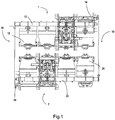
- the dual power supply switching device comprises: one power supply switch 1; another power supply switch 2; and two mechanical interlocks 10 arranged on both sides of the dual power supply switching device in a centrally symmetrical manner.
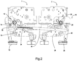
- Fig. 2 illustrates details of the structure of the mechanical interlock 10 according to an embodiment of the disclosure.
- the mechanical interlock 10 comprises: a first interlock lever 30 that is coupled with a crank of a spindle 12 of the one power supply switch 1 of the dual power supply switching device and is configured to move in response to the closing of said one power supply switch 1, wherein when said one power supply switch 1 is closed, the spindle 12 of said one power supply switch 1 is rotated in a first direction; a second interlock lever 40 that is pivotally connected with the first interlock lever 30, is also pivotally connected with a base of the dual power supply switching device, and is configured to rotate in a second direction opposite to the first direction in response to the movement of the first interlock lever 30; wherein a trip lever 24 of the other power supply switch 2 of the dual power supply switching device is configured to be in a rotation path of the second interlock lever 40 and is configured to be abutted (or contacted) by the second interlock lever 40 in the rotation path of the second interlock lever 40 so as to keep the other power supply switch 2 at a tripped (or opened) state
- the spindle of one power supply switch serves as an active lever which moves in association with the mechanical interlock; the mechanical interlock, as a follower device, acts upon a mechanical trip lever of the other power supply switch so as to maintain the tripped state of the other power supply switch, thus reliably avoiding a simultaneous closing of the two power supplies; even if in a situation of misoperation, simultaneous closing of the two power supplies can be avoided.
- a crank is fixedly connected with the spindle 12 of said one power supply switch 1, an end of the first interlock lever 30 is hinged to the crank or forms a sliding pair with the crank, the first interlock lever 30 is hinged to the second interlock lever 40, and the first interlock lever 30 is also hinged to a base (which is a fixed element).
- the first interlock lever 30 moves as the crank rotates, thus driving the second interlock lever 40 to swing around a shaft hinged to the base.
- the first interlock lever 30 is provided with a slide groove 32 so that the first interlock lever 30 is coupled with the spindle 12 of said one power supply switch 1 in a way of sliding relative to each other.
- the sliding pair can be used to alleviate the difficulty in designing the positions of the spindles, the crank, the first and second interlock levers as well as the travel stroke of the trip lever, thus effectively avoiding interference between elements.
- a hinged connection can be also used between the crank and the first interlock lever according to the rotation angles of the spindles, the length of the crank, the positions of the first and second interlock levers and the travel of the trip lever.
- a biasing member 34 is disposed between a crank of the spindle 12 of said one power supply switch 1 and the first interlock lever 30, and is configured to bias the first interlock lever 30 in response to the closing of said one power supply switch 1 so as to accelerate the movement of the second interlock lever 40.
- the biasing member is for example a spring, an end of which is disposed on the crank, and the other end of which is disposed on the first interlock lever 30. A pre-tensioning force is applied to the spring.
- the crank contacts a side of the slide groove (which is an oblong hole in the illustrated example) that has a shorter length.
- the pre-tensioning force is preferably larger than a tripping force for tripping the other mechanism of the other power supply switch. In this situation, the tripping of the other power supply switch can be triggered more quickly.
- the inventor of the application has conducted detailed simulation analysis on the force components for closing and opening, and has found that by providing a damping member so as to consume the closing energy at an early stage of closing, the energy accumulated for driving the spindles is optimally smaller than zero before the movable and stationary contacts contact each other; that is, a movement in the opening direction is satisfied, and it is ensured that a short circuit between the two power supplies will not occur, thus protecting the safety of lines.
- the damping member is a spring, an end of which is disposed on the spindle of said one power supply switch, another end of which is disposed on a housing of the dual power supply switching device, and which is configured to apply a resistant force to the spindle of said one power supply switch at least at an early stage of the closing movement of said one power supply switch.
- the mechanical interlock 10 further comprises a blocking assembly 50 which moves in association with the closing movement of said one power supply switch 1 and which is configured such that when the other power supply switch 2 is normally closed, the blocking assembly 50 is located outside the closing path of the other power supply switch 2, and when said one power supply switch 1 and the other power supply switch 2 are closed simultaneously, at least one part of the blocking assembly 50 moves to the closing path of the other power supply switch 2 in association with the closing movement of said one power supply switch 1, and blocks the closing movement of the other power supply switch 2.
- a blocking assembly 50 which moves in association with the closing movement of said one power supply switch 1 and which is configured such that when the other power supply switch 2 is normally closed, the blocking assembly 50 is located outside the closing path of the other power supply switch 2, and when said one power supply switch 1 and the other power supply switch 2 are closed simultaneously, at least one part of the blocking assembly 50 moves to the closing path of the other power supply switch 2 in association with the closing movement of said one power supply switch 1, and blocks the closing movement of the other power supply switch 2.
- the blocking assembly 50 comprises a blocking link 52, an end of which is pivotally connected to the housing of the dual power supply switching device, another end of which is coupled with the second interlock lever 40 in a way of sliding relative to each other, and which is configured to rotate when driven by the second interlock lever 40 during the closing of said one power supply switch 1 so as to abut the crank of the spindle 22 of the other power supply switch 2, thus in turn blocking the closing of the other power supply switch 2.
- the blocking link 52 comprises a protrusion 54 which protrudes towards the spindle 22 of the other power supply switch 2 from the blocking link 52.
- the blocking link 52 and the protrusion 54 are the same member or integral member.
- the blocking link 52 is pivotally connected to the housing of the dual power supply switching device, and is also slidingly coupled with the second interlock lever 40.
- the blocking link 52 and the protrusion 54 will rotate together (clockwise in the drawing) due to being driven by the second interlock lever 40 so that they will come closer to the crank of the spindle 22 of the other power supply switch 2.
- the trip lever 24 is pushed by the second interlock lever 40 until it reaches the limit position, the elastic member will begin to be stretched.
- the spindle 22 drives the crank to rotate (counterclockwise), and the protrusion 54 stops moving due to the blocking link 52.
- the spindle 22 continues to move in the closing direction (counterclockwise) until the crank 22 is blocked by the protrusion 54, the spindles 12, 22 will continue to rotate in the opening direction under the action of opening spring after a small impact, thus ensuring a short circuit between the two power supplies will not occur, thus protecting the safety of lines.
- a method of operating dual power supply switching device is also provided.
- the method of the application can also provide safe and reliable interlocking, and prevent safety accidents such as short circuit between power supplies or the like.
Landscapes
- Physics & Mathematics (AREA)
- Electromagnetism (AREA)
- Business, Economics & Management (AREA)
- Emergency Management (AREA)
- Engineering & Computer Science (AREA)
- Power Engineering (AREA)
- Driving Mechanisms And Operating Circuits Of Arc-Extinguishing High-Tension Switches (AREA)
- Stand-By Power Supply Arrangements (AREA)
Applications Claiming Priority (1)
| Application Number | Priority Date | Filing Date | Title |
|---|---|---|---|
| CN201610875113.5A CN107887200B (zh) | 2016-09-30 | 2016-09-30 | 机械联锁装置、双电源转换开关以及用于操作其的方法 |
Publications (2)
| Publication Number | Publication Date |
|---|---|
| EP3301698A2 true EP3301698A2 (de) | 2018-04-04 |
| EP3301698A3 EP3301698A3 (de) | 2018-04-25 |
Family
ID=60080727
Family Applications (1)
| Application Number | Title | Priority Date | Filing Date |
|---|---|---|---|
| EP17306296.9A Withdrawn EP3301698A3 (de) | 2016-09-30 | 2017-09-29 | Mechanische verriegelung, schaltvorrichtung mit dualer stromversorgung und verfahren zum betrieb davon |
Country Status (2)
| Country | Link |
|---|---|
| EP (1) | EP3301698A3 (de) |
| CN (1) | CN107887200B (de) |
Cited By (6)
| Publication number | Priority date | Publication date | Assignee | Title |
|---|---|---|---|---|
| CN108735534A (zh) * | 2018-06-26 | 2018-11-02 | 上海良信电器股份有限公司 | 一种双电源自动转换开关的机械联锁机构 |
| CN109103045A (zh) * | 2018-10-15 | 2018-12-28 | 国网河南省电力公司济源供电公司 | 一种实现双母线隔离开关主刀地刀机械闭锁装置 |
| CN109360753A (zh) * | 2018-11-06 | 2019-02-19 | 安士缔(中国)电气设备有限公司 | 中压双电源自动切换开关的机械连锁装置及双电源装置 |
| CN110323829A (zh) * | 2019-07-13 | 2019-10-11 | 广东正超电气有限公司 | 双电源切换装置的联锁机构 |
| CN113410074A (zh) * | 2020-03-16 | 2021-09-17 | 施耐德电器工业公司 | 一种双电源转换开关 |
| CN116779355A (zh) * | 2023-08-17 | 2023-09-19 | 希格玛电气(珠海)有限公司 | 一种双电源进线柜的二合一机械联锁装置 |
Families Citing this family (4)
| Publication number | Priority date | Publication date | Assignee | Title |
|---|---|---|---|---|
| CN112447426B (zh) * | 2019-09-04 | 2024-08-13 | Abb瑞士股份有限公司 | 机械联锁装置和双电源供电系统 |
| CN113708161B (zh) * | 2020-05-20 | 2024-12-10 | 霸士电器(昆山)有限公司 | 电连接系统及机械联锁装置 |
| WO2023123281A1 (en) * | 2021-12-30 | 2023-07-06 | Abb Schweiz Ag | Interlock device |
| CN118380283B (zh) * | 2024-06-25 | 2024-09-20 | 亨斯迈(杭州)电力技术有限公司 | 一种用于双电源控制的电磁机械联锁装置 |
Family Cites Families (9)
| Publication number | Priority date | Publication date | Assignee | Title |
|---|---|---|---|---|
| US2531157A (en) * | 1949-08-18 | 1950-11-21 | Gen Electric | Reciprocal dual circuit breaker double interlock mechanism |
| US2573485A (en) * | 1950-10-07 | 1951-10-30 | Gen Electric | Multiple releasable interlocking mechanism for circuit breakers |
| US6486421B1 (en) * | 2000-04-27 | 2002-11-26 | Eaton Corporation | Mechanical interlock with overtravel compensation for coordinating operation of circuit breakers |
| CN102610430B (zh) * | 2012-03-08 | 2016-03-16 | 安徽宇腾真空电气有限责任公司 | 一种永磁式高压真空断路器 |
| CN103681031B (zh) * | 2012-08-30 | 2015-12-09 | 上海电科电器科技有限公司 | 转换开关的联锁装置 |
| CN204117887U (zh) * | 2014-09-15 | 2015-01-21 | 浙江正泰电器股份有限公司 | 一种自动转换开关电器的联锁装置 |
| CN205282324U (zh) * | 2015-11-24 | 2016-06-01 | 施耐德电气工业公司 | 双电源转换开关 |
| CN205159152U (zh) * | 2015-11-30 | 2016-04-13 | 施耐德电气工业公司 | 双电源自动转换开关 |
| CN206059218U (zh) * | 2016-09-30 | 2017-03-29 | 施耐德电气工业公司 | 机械联锁装置以及双电源转换开关 |
-
2016
- 2016-09-30 CN CN201610875113.5A patent/CN107887200B/zh active Active
-
2017
- 2017-09-29 EP EP17306296.9A patent/EP3301698A3/de not_active Withdrawn
Non-Patent Citations (1)
| Title |
|---|
| None |
Cited By (8)
| Publication number | Priority date | Publication date | Assignee | Title |
|---|---|---|---|---|
| CN108735534A (zh) * | 2018-06-26 | 2018-11-02 | 上海良信电器股份有限公司 | 一种双电源自动转换开关的机械联锁机构 |
| CN109103045A (zh) * | 2018-10-15 | 2018-12-28 | 国网河南省电力公司济源供电公司 | 一种实现双母线隔离开关主刀地刀机械闭锁装置 |
| CN109360753A (zh) * | 2018-11-06 | 2019-02-19 | 安士缔(中国)电气设备有限公司 | 中压双电源自动切换开关的机械连锁装置及双电源装置 |
| CN109360753B (zh) * | 2018-11-06 | 2024-01-19 | 安士缔(中国)电气设备有限公司 | 中压双电源自动切换开关的机械连锁装置及双电源装置 |
| CN110323829A (zh) * | 2019-07-13 | 2019-10-11 | 广东正超电气有限公司 | 双电源切换装置的联锁机构 |
| CN113410074A (zh) * | 2020-03-16 | 2021-09-17 | 施耐德电器工业公司 | 一种双电源转换开关 |
| CN116779355A (zh) * | 2023-08-17 | 2023-09-19 | 希格玛电气(珠海)有限公司 | 一种双电源进线柜的二合一机械联锁装置 |
| CN116779355B (zh) * | 2023-08-17 | 2024-03-26 | 希格玛电气(珠海)有限公司 | 一种双电源进线柜的二合一机械联锁装置 |
Also Published As
| Publication number | Publication date |
|---|---|
| EP3301698A3 (de) | 2018-04-25 |
| CN107887200B (zh) | 2020-01-03 |
| CN107887200A (zh) | 2018-04-06 |
Similar Documents
| Publication | Publication Date | Title |
|---|---|---|
| EP3301698A2 (de) | Mechanische verriegelung, schaltvorrichtung mit dualer stromversorgung und verfahren zum betrieb davon | |
| US8803640B2 (en) | Remote operated circuit breaker | |
| EP2015340B1 (de) | Verzögerungsausgabegerät für einen Schutzschalter | |
| CN206059218U (zh) | 机械联锁装置以及双电源转换开关 | |
| CN106409563A (zh) | 断路器与三工位开关连锁装置及断路器‑三工位开关装置 | |
| KR100942567B1 (ko) | 가스절연 차단기용 스프링 조작기 | |
| US8772666B2 (en) | Interlock system for switchgear | |
| US7045733B2 (en) | Low-voltage circuit-breaker and corresponding positive-opening-operation device | |
| US9431185B2 (en) | Spring operation device for switchgear | |
| KR20120038468A (ko) | 지연 회로를 갖는 스프링 작동 메커니즘 | |
| KR102226948B1 (ko) | 순시차단용 구동장치 | |
| KR20150134388A (ko) | 스위치 장치용 구동부 | |
| US10008355B2 (en) | Control system for a breaker pole with forcing, and breaker gear | |
| KR101699699B1 (ko) | 회로 차단기용 스위치 잠금장치 | |
| EP4540851B1 (de) | Rückprallschutzvorrichtung und schutzschalter damit | |
| KR101797023B1 (ko) | 부하개폐기의 과투입 방지 구조 | |
| CN221508003U (zh) | 电气开关 | |
| JP2020068143A (ja) | ガス遮断器 | |
| KR200454285Y1 (ko) | 기중차단기의 리바운딩에의한 재투입 방지장치 | |
| KR102820128B1 (ko) | 분리가능한 접촉부들을 갖는 전기 스위칭 유닛 | |
| CN117711887A (zh) | 断路器 | |
| KR200398419Y1 (ko) | 진공 차단기의 다절 링크식 작동기구 | |
| EP3048631A1 (de) | Verfahren zum Betrieb eines Schutzschalters und Schutzschalter | |
| KR200396951Y1 (ko) | 회로차단기 | |
| CN119340168A (zh) | 断路器 |
Legal Events
| Date | Code | Title | Description |
|---|---|---|---|
| PUAI | Public reference made under article 153(3) epc to a published international application that has entered the european phase |
Free format text: ORIGINAL CODE: 0009012 |
|
| STAA | Information on the status of an ep patent application or granted ep patent |
Free format text: STATUS: THE APPLICATION HAS BEEN PUBLISHED |
|
| PUAL | Search report despatched |
Free format text: ORIGINAL CODE: 0009013 |
|
| AK | Designated contracting states |
Kind code of ref document: A2 Designated state(s): AL AT BE BG CH CY CZ DE DK EE ES FI FR GB GR HR HU IE IS IT LI LT LU LV MC MK MT NL NO PL PT RO RS SE SI SK SM TR |
|
| AX | Request for extension of the european patent |
Extension state: BA ME |
|
| RIC1 | Information provided on ipc code assigned before grant |
Ipc: H01H 9/26 20060101ALI20180315BHEP Ipc: H01H 31/10 20060101AFI20180315BHEP |
|
| AK | Designated contracting states |
Kind code of ref document: A3 Designated state(s): AL AT BE BG CH CY CZ DE DK EE ES FI FR GB GR HR HU IE IS IT LI LT LU LV MC MK MT NL NO PL PT RO RS SE SI SK SM TR |
|
| AX | Request for extension of the european patent |
Extension state: BA ME |
|
| STAA | Information on the status of an ep patent application or granted ep patent |
Free format text: STATUS: REQUEST FOR EXAMINATION WAS MADE |
|
| 17P | Request for examination filed |
Effective date: 20180530 |
|
| RBV | Designated contracting states (corrected) |
Designated state(s): AL AT BE BG CH CY CZ DE DK EE ES FI FR GB GR HR HU IE IS IT LI LT LU LV MC MK MT NL NO PL PT RO RS SE SI SK SM TR |
|
| STAA | Information on the status of an ep patent application or granted ep patent |
Free format text: STATUS: EXAMINATION IS IN PROGRESS |
|
| 17Q | First examination report despatched |
Effective date: 20201022 |
|
| STAA | Information on the status of an ep patent application or granted ep patent |
Free format text: STATUS: THE APPLICATION IS DEEMED TO BE WITHDRAWN |
|
| 18D | Application deemed to be withdrawn |
Effective date: 20240403 |