EP3301753A1 - Multiplexvorrichtung und verfahren zur verwendung davon - Google Patents
Multiplexvorrichtung und verfahren zur verwendung davon Download PDFInfo
- Publication number
- EP3301753A1 EP3301753A1 EP17275152.1A EP17275152A EP3301753A1 EP 3301753 A1 EP3301753 A1 EP 3301753A1 EP 17275152 A EP17275152 A EP 17275152A EP 3301753 A1 EP3301753 A1 EP 3301753A1
- Authority
- EP
- European Patent Office
- Prior art keywords
- connection port
- radio frequency
- path
- receive
- transmit
- Prior art date
- Legal status (The legal status is an assumption and is not a legal conclusion. Google has not performed a legal analysis and makes no representation as to the accuracy of the status listed.)
- Withdrawn
Links
- 238000000034 method Methods 0.000 title claims description 10
- 238000001914 filtration Methods 0.000 claims abstract description 5
- 230000008878 coupling Effects 0.000 claims description 26
- 238000010168 coupling process Methods 0.000 claims description 26
- 238000005859 coupling reaction Methods 0.000 claims description 26
- 230000005540 biological transmission Effects 0.000 claims description 15
- 239000003990 capacitor Substances 0.000 claims description 4
- 230000037361 pathway Effects 0.000 description 40
- 238000010586 diagram Methods 0.000 description 10
- 238000002955 isolation Methods 0.000 description 6
- 238000003780 insertion Methods 0.000 description 4
- 230000037431 insertion Effects 0.000 description 4
- MWRWFPQBGSZWNV-UHFFFAOYSA-N Dinitrosopentamethylenetetramine Chemical compound C1N2CN(N=O)CN1CN(N=O)C2 MWRWFPQBGSZWNV-UHFFFAOYSA-N 0.000 description 2
- 238000010295 mobile communication Methods 0.000 description 2
- 230000003321 amplification Effects 0.000 description 1
- 229940112112 capex Drugs 0.000 description 1
- 230000009977 dual effect Effects 0.000 description 1
- 238000005516 engineering process Methods 0.000 description 1
- FEBLZLNTKCEFIT-VSXGLTOVSA-N fluocinolone acetonide Chemical compound C1([C@@H](F)C2)=CC(=O)C=C[C@]1(C)[C@]1(F)[C@@H]2[C@@H]2C[C@H]3OC(C)(C)O[C@@]3(C(=O)CO)[C@@]2(C)C[C@@H]1O FEBLZLNTKCEFIT-VSXGLTOVSA-N 0.000 description 1
- 238000009434 installation Methods 0.000 description 1
- 238000003199 nucleic acid amplification method Methods 0.000 description 1
Images



Classifications
-
- H—ELECTRICITY
- H01—ELECTRIC ELEMENTS
- H01P—WAVEGUIDES; RESONATORS, LINES, OR OTHER DEVICES OF THE WAVEGUIDE TYPE
- H01P1/00—Auxiliary devices
- H01P1/20—Frequency-selective devices, e.g. filters
- H01P1/213—Frequency-selective devices, e.g. filters combining or separating two or more different frequencies
-
- H—ELECTRICITY
- H04—ELECTRIC COMMUNICATION TECHNIQUE
- H04B—TRANSMISSION
- H04B1/00—Details of transmission systems, not covered by a single one of groups H04B3/00 - H04B13/00; Details of transmission systems not characterised by the medium used for transmission
- H04B1/06—Receivers
- H04B1/10—Means associated with receiver for limiting or suppressing noise or interference
- H04B1/12—Neutralising, balancing, or compensation arrangements
Definitions
- This invention relates to multiplexer apparatus and to a method of use thereof, and particularly to multiplexer apparatus of a type for combining and/or splitting radio frequency (RF) signals.
- RF radio frequency
- Mobile phone operators seek to minimise the capital expenditure (capex) required to build a wireless network as well as minimise the ongoing operating expenditure (opex). If an operator provides both 3G (3rd generation mobile communication) and 4G (4th generation mobile communication) wireless network services then a way to reduce opex is for the two networks to share a cell site. However, the sharing of cell sites typically results in complex logistics relating to the installation of the cell sites.
- FIG. 1a An example of a typical cell site arrangement, forming part of a wireless telecommunications network, in which two different wireless technology service networks share the same site, is shown in figure 1a .
- the 3G and 4G services of a particular operator share the same mast.
- the 3G and 4G services are in different frequency operating bands (for example 900MHz and 1800MHz respectively).
- Multiplexing apparatus in the form of a diplexer unit is provided to allow combining and/or splitting of RF signals so that equipment on the mast can be shared.
- the cell site includes a mast 2, at the top of which is mounted a 900MHz antenna 4 for transmitting and/or receiving one or more radio frequency signals in the 900MHz frequency band, and a 1800MHz antenna 6 for transmitting and/or receiving one or more radio frequency signals in the 1800MHz frequency band.
- a diplexer unit 8 is provided at the top of mast 2 for receiving radio frequency signals from the 1800MHz antenna 6 and the 900MHz antenna 4 and combining the same into a common feeder cable 9.
- diplexer unit 8 splits the combined transmit signals in the 900MHz and 1800 MHz frequency bands that have been transmitted along common feeder cable 9 and transmit the 900MHz and 1800MHz signals to the 900MHz antenna 4 and the 1800MHz antenna 6 respectively.
- a further diplexer unit 10 provided at the base of mast 2 splits the combined RF signals in the 900MHz and 1800MHz frequency bands being received from cable 9 for passage to a 900MHz base station (BTS) 12 and 1800MHz base station (BTS) 14 respectively located at the base of mast 2.
- Diplexer unit 10 also takes RF signals transmitted from the BTSs 12, 14 and combines the same for passage along common feeder cable 9 to diplexer unit 8 at the top of the mast.
- Each BTS 12, 14 typically includes a transceiver that generates one or more radio frequency signals for transmission to a mobile phone unit via the antennae 4, 6, as well as receiving one or more radio frequency signals from a mobile phone unit via antennae 4, 6.
- Figure 1b is a circuit diagram showing the filter arrangement of the conventional diplexer unit 10.
- the unit 10 typically comprises a housing 22 having a 900MHz channel port 24 for connection to 900MHz BTS 12, and a 1800MHz channel port 26 for connection to 1800MHz BTS 14.
- a common port 28 is provided for transmitting and/or receiving the combined 1800MHz and 900MHz RF signals.
- Diplexer Unit 10 includes a 900MHz filter 30 provided between the 900MHz channel port 24 and common port 28 for allowing the passage of transmit and/or receive RF signals in the 900MHz frequency band, but for substantially preventing passage of transmit and/or receive RF signals at any other frequency.
- Unit 10 includes a 1800MHz filter 32 provided between the 1800MHz channel port 26 and common port 28 for allowing the passage of transmit and/or receive RF signals in the 1800MHz frequency band, but for substantially preventing passage of transmit and/or receive RF signals at any other frequency.
- the ends 34, 34' of filters 30, 32 are multiplexed together to provide a common signal path 36 connected to common port 28.
- FIG. 2 is a further example of a circuit diagram showing the filter arrangement of a conventional diplexer unit 102.
- the connection port 24 is a transmit port for the transmission of one or more transmit RF signals at a particular RF frequency
- the connection port 26 is a receive port for receiving one or more receive RF signals at a particular RF frequency
- the common port 28 is for connection to an antenna.
- a transmission RF pathway 34 is provided between transmit port 24 and the common port 28, and a receive RF pathway 34' is provided between receive port 26 and the common port 28.
- a transmission filter 30 is provided in transmit pathway 34 for allowing the passage of one or more transmit RF signals at a particular frequency therethrough but to substantially prevent the passage of any other RF signal therethrough, and a receive filter 32 is provided in receive pathway 34' for allowing the passage of one or more receive RF signals at a particular frequency therethrough but to substantially prevent the passage of any other RF signal therethrough.
- One end of each of the filters 30, 32 are multiplexed together as previously described to form a common path to common port 28.
- Amplification means are connected to each of the transmit port 24 and the receive port 26 for amplifying the transmission and receive signals entering and leaving the diplexer unit 102 respectively.
- Multiplexer apparatus including:
- the multiplexer apparatus of the present invention provides significantly improved isolation between the first and second channel ports, or between the transmit connection port and the receive connection port, in use.
- the multiplexer apparatus is in the form of a diplexer unit.
- connection port is electrically terminated in a match, impedance or load that is equal to or substantially equal to a match, impedance or load applied to the common connection port.
- the RF amplitude response in the path between the at least first and second channel connection ports via the first and second paths is equal to or substantially equal to the RF amplitude response in the path between the at least first and second channel connection ports via the third and fourth paths.
- the RF amplitude response in the path between the transmit RF connection port and the receive RF connection port via the first and second paths is equal to or substantially equal to the RF amplitude response in the path between the at least transmit and receive connection ports via the third and fourth paths.
- the path between the at least first and second connection ports, or between the transmit and receive RF connection ports, via the first and second paths has a 180 or substantially 180 degree phase difference to the path between the at least first and second connection ports, or between the transmit and receive RF connection ports, via the third and fourth paths.
- the RF amplitude response between the filter means in the first RF path is equal to or substantially equal to the RF amplitude response of the filter means in the fourth RF path.
- the RF amplitude response between the filter means in the second RF path is equal to or substantially equal to the RF amplitude response of the filter means in the third RF path.
- the filter means within a particular path can consist of a single filter.
- the filter means within a particular path can consist of two or more filters.
- the filter means is typically any device which allows the passage one or more of more RF signals therethrough of a first frequency or set of frequencies, and which prevents or substantially prevents the passage of one or more RF signals therethrough of a frequency other than said first frequency or set of frequencies.
- the filter means can include any or any combination of one or more low pass filters, high pass filters, passband filters, band stop filters and/or the like.
- the filter means in the first and fourth paths are transmission filter means for allowing one or more transmission signals at a first frequency or set of frequencies to pass therethrough, but to prevent or substantially prevent one or more other signals from passing therethrough.
- the filter means in the second and third paths are receive filter means for allowing one or more receive signals at a second of second set of frequencies to pass therethrough, but to prevent or substantially prevent one or more other signals from passing therethrough.
- the first frequency or set of frequencies is different to or substantially different to the second frequency or set of frequencies.
- the further connection port that is electrically terminated can include any or any combination of impedance means or device, resistor means, capacitor means, inductor means, or one or more resistors, capacitors, inductors and/or the like.
- the filter means in any or any combination of the pathways are or include one or more tuneable filters to allow the filter means to be tuned so as to operate at a particular frequency or set of frequencies.
- the one or more tuneable filters are tuneable using tuning means.
- connection port and/or the further connection port are tuneable and/or are provided with or associated with tuning means to allow the match or load applied to the connection ports to be made equal or substantially equal to each other.
- the tuning means can include any or any combination of one or more rotatable screws, threaded screws, tuning screws and/or the like.
- the tuning means are anything that allows the radio frequency response of the filter means, or match, impedance or load applied to the connection ports, to be adjusted in use.
- the multiplexer apparatus includes a housing in which the circuitry of the apparatus is provided.
- the first channel connection port is arranged to receive and/or transmit one or more RF signals at a first frequency, first set of frequencies or first frequency range
- the second channel connection port is arranged to receive and/or transmit one or more RF signals at a second frequency, second set of frequencies or second frequency range.
- the first frequency, first set of frequencies or first frequency range is different or substantially different to the second frequency, second set of frequencies, or second frequency range.
- the first transmit RF connection port is arranged to transmit one or more RF signals at a particular frequency or frequencies
- the second receive RF connection port is arranged to receive one or more RF signals at a particular frequency or frequencies
- the transmit RF signals and the receive RF signals are preferably at different or substantially different frequency or frequencies.
- the 180 degree phase difference in the path between the first and second channel connection ports, or between the transmit and receive RF connection ports, via the first and second RF pathways, and the path between the first and second connection ports, or between the transmit and receive RF connection ports, via the third and fourth RF pathways can be caused by phase shifting means.
- phase shifting means is in the form of a transmission line having an electrical length of 180 degrees.
- phase shifting means is provided in any of the first, second, third or fourth RF paths, and further preferably is provided in any of the first, second, third or fourth RF path between the channel connection port or the receive or transmit connection ports and the filter means in said path.
- the 180 degree phase difference between the path between the first and second channel ports, or between the transmit and receive RF connection ports, via the first and second RF paths, and the path between the first and second channel ports, or between the transmit and receive RF connection ports, via the third and fourth RF paths can be caused by providing at least one different type of coupling within and/or between the paths.
- the at least one different type of coupling could be an electrical coupling, a magnetic coupling, a positive coupling, a negative coupling and/or the like.
- the couplings are provided between one or more resonators or resonating means in or associated with the filter means, between the input or output ports of the filter means and/or the like.
- first and second RF pathways could have all positive couplings provided therein and the third and fourth RF paths could have one negative coupling or vice versa.
- first and second RF paths could have all electrical couplings provided therein and the third and fourth RF paths could have one magnetic coupling provided therein or vice versa.
- the 180 degree phase difference between the first and second RF paths and the third and fourth RF paths can be caused by arranging the first and fourth filter means to have an equal or substantially equal RF amplitude and phase response, and arranging the second and third filter means to have an equal or substantially equal RF amplitude response but a phase response that is opposite or substantially opposite.
- the apparatus includes at least one further circuit of the same or similar type to the first circuit described above.
- the further circuit is a mirror image of the first circuit. This provides a dual multiplexer apparatus or a multi-circuit multiplexer apparatus.
- a method of using multiplexer apparatus including:
- a telecommunication system including multiplexer apparatus.
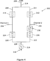
- multiplexer apparatus in the form of a diplexer unit 202 according to an embodiment of the present invention.
- Diplexer unit 202 has a first channel connection port 204 for transmitting and/or receiving RF signals at a first set of frequencies or frequency range, and a second channel connection port 206 for transmitting and/or receiving one or more RF signals at a second set of frequencies or frequency range.
- the first set of frequencies or frequency range is different to the second set of frequencies or frequency range.
- a common connection port 208 is provided.
- a first RF pathway 209 is provided between first channel port 204 and the common connection port 208, and a second RF pathway 211 is provided between second channel port 206 and the common connection port 208.
- a first filter 210 is provided in the first pathway 209 for allowing one or more RF signals of the first set of frequencies or frequency range to pass therethrough but to prevent or substantially prevent one or more RF signals of any other frequency from passing therethrough.
- a second filter 212 is provided in the second pathway 211 for allowing one or more RF signals of the second set of frequencies or frequency range to pass therethrough but to prevent or substantially prevent one or more RF signals of any other frequency from passing therethrough.
- filters 210, 212 are multiplexed together to form a common pathway 214 to join to common connection port 208.
- a fourth or further connection port 216 is provided and this port is electrically terminated with an impedance.
- the impedance is to ground 218.
- a third RF pathway 220 is provided between the first channel port 204 and the fourth connection port 216, and a fourth RF pathway 222 is provided between the second channel port 206 and the fourth connection port 216.
- a third filter 224 is provided in the third pathway 220 for allowing one or more RF signals of a third set of frequencies or frequency range to pass therethrough but to prevent or substantially prevent one or more RF signals of any other frequency from passing therethrough.
- a fourth filter 226 is provided in the fourth pathway 222 for allowing one or more RF signals of a fourth set of frequencies or frequency range to pass therethrough but to prevent or substantially prevent one or more RF signals of any other frequency from passing therethrough.
- the ends of filters 224, 226 are multiplexed together to form a common pathway 228 for connection to fourth connection port 216.
- the third set of frequencies or frequency range is typically equal or substantially equal to the second set of frequencies or frequency range.
- the fourth set of frequencies or frequency range is typically equal to substantially equal to the first set of frequencies or frequency range.
- the match or load of the fourth connection port 216 is equal or substantially equal to the match or load of the common connection port 208. In one example this can be achieved by providing tuning means on or associated with the common connection port 208 and/or the fourth connection port 216.
- the RF amplitude response of one set of diagonally arranged filters in the circuit diagram needs to be equal or substantially equal to the RF amplitude response of the other set of diagonal filters.
- the RF amplitude response of filter 210 is equal to or substantially equal to the RF response of filter 226, and the RF amplitude response of filter 212 is equal to or substantially equal to the RF response of filter 224.
- the path between the first and second connection ports 204, 206 via the first and second RF pathways 209, 211 needs to have a 180 degree or substantially 180 degrees phase difference to the path between the first and second connection ports 204, 206 via the third and fourth RF pathways 220, 222.
- This phase difference can be achieved by suitable choice of couplings.
- the input / output couplings and all inter resonator couplings in the first RF pathway could be of identical type to those in the fourth RF pathway but the second RF pathway could have a single input coupling that was of a different type to an input coupling in the third RF pathway with all other couplings in the second and third RF pathways being of identical type.
- the different types could be achieved by replacing a magnetic coupling with an electrical coupling or vice versa for example.
- the result of the filter arrangement above is that the amplitude of the leakage of RF signals in the path between the first and second connection ports 204, 206 via the first and second RF pathways 209, 211 is equal to or substantially equal to the amplitude of the leakage of second of RF signals in the path between the first and second connection ports 204, 206 via the third and fourth RF pathways 220, 222.
- this allows the leakage of RF signals in the pathways to cancel each other out.
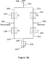
- Figure 3b shows a further embodiment of the present invention with similar circuitry to the embodiment shown in figure 3a .
- the first channel port 204 is a transmission connection port for transmitting one or more RF signals and the second channel port 206 is a receive connection port for receiving one or more RF signals.
- the common channel port 208 is an antenna connection port for transmitting and/or receiving the RF signals.
- the first filter 210 in the first RF pathway 209 and the fourth filter 226 in the fourth RF pathway 222 are both transmit filters for allowing the passage of one or more transmit signals therethrough at a transmission RF frequency or frequency range but preventing or substantially preventing the passage of any other signal therethrough.
- the second filter 212 in the second RF pathway 211 and the third filter 224 in the third RF pathway 220 are both receive filters for allowing the passage of one or more receive signals therethrough at a receive RF frequency or frequency range but preventing or substantially preventing the passage of any other signal therethrough.
- the result of the filter arrangement ensures that the amplitude of the leakage of RF signals between the transmit and receive ports via the first and second pathways 209, 211, is equal to or substantially equal to the amplitude of the leakage of RF signals between the transmit and receive ports via the third and fourth pathways.
- this allows the leakage of RF signals in the pathways to cancel each other out.
- This creates high isolation between the transmission and receive channel ports 204, 206, irrespective of the order of filters used. This allows lower order filters to be used for filters 210, 212, 224 and 226, thereby saving on cost and space and reducing complexity of the apparatus. In addition, lower order filters results in low insertion loss.
- diplexer apparatus according to one embodiment that is similar to the embodiment shown in figure 3a , with the exception that a 180 degree phase shifter 230 is provided in the fourth RF pathway 222 between the second channel port 206 and the fourth filter 226.
- the 180 degree phase shifter in this embodiment is a transmission line having an electrical length of 180 degrees.
- the use of the 180 degree phase shifter allows the filters 210 and 226 to have an equal or substantially equal RF amplitude and phase response, and the filters 212, 224 to have an equal or substantially equal RF amplitude and phase response.
- diplexer apparatus according to one embodiment that is similar to the embodiment shown in figure 3a , with the exception that the filters 210, 212, 224 and 226 are tunable filters, in that the RF response or passband frequency of each of the filters can be tuned using tuning means, such as for example, a tuning screw.
- tuning means such as for example, a tuning screw.
- the ability to use tunable filters in the diplexer unit is as a result of lower order filters being used.
- the filters can be tuned in use in the field.
- the multiplexer apparatus of the present invention could be used in mobile handsets, in satellite systems, in mobile devices, in tablets and/or the like.
Landscapes
- Engineering & Computer Science (AREA)
- Computer Networks & Wireless Communication (AREA)
- Signal Processing (AREA)
- Transceivers (AREA)
Applications Claiming Priority (1)
| Application Number | Priority Date | Filing Date | Title |
|---|---|---|---|
| GBGB1616637.3A GB201616637D0 (en) | 2016-09-30 | 2016-09-30 | Multiplexer apparatus and method of use thereof |
Publications (1)
| Publication Number | Publication Date |
|---|---|
| EP3301753A1 true EP3301753A1 (de) | 2018-04-04 |
Family
ID=57570985
Family Applications (1)
| Application Number | Title | Priority Date | Filing Date |
|---|---|---|---|
| EP17275152.1A Withdrawn EP3301753A1 (de) | 2016-09-30 | 2017-09-29 | Multiplexvorrichtung und verfahren zur verwendung davon |
Country Status (2)
| Country | Link |
|---|---|
| EP (1) | EP3301753A1 (de) |
| GB (1) | GB201616637D0 (de) |
Cited By (2)
| Publication number | Priority date | Publication date | Assignee | Title |
|---|---|---|---|---|
| WO2019192728A1 (en) * | 2018-04-06 | 2019-10-10 | Huawei Technologies Co., Ltd. | A duplex filter arrangement with leakage cancellation |
| DE102018112847A1 (de) * | 2018-05-29 | 2019-12-05 | RF360 Europe GmbH | Multiplexerschaltung mit verbesserter Isolation und Multiplexer-Bauelement |
Citations (2)
| Publication number | Priority date | Publication date | Assignee | Title |
|---|---|---|---|---|
| WO2002084686A1 (en) * | 2001-04-11 | 2002-10-24 | Kyocera Wireless Corporation | Band switchable filter |
| US9319208B2 (en) * | 2012-01-10 | 2016-04-19 | Rf Micro Devices, Inc. | RF duplexing device |
-
2016
- 2016-09-30 GB GBGB1616637.3A patent/GB201616637D0/en not_active Ceased
-
2017
- 2017-09-29 EP EP17275152.1A patent/EP3301753A1/de not_active Withdrawn
Patent Citations (2)
| Publication number | Priority date | Publication date | Assignee | Title |
|---|---|---|---|---|
| WO2002084686A1 (en) * | 2001-04-11 | 2002-10-24 | Kyocera Wireless Corporation | Band switchable filter |
| US9319208B2 (en) * | 2012-01-10 | 2016-04-19 | Rf Micro Devices, Inc. | RF duplexing device |
Cited By (5)
| Publication number | Priority date | Publication date | Assignee | Title |
|---|---|---|---|---|
| WO2019192728A1 (en) * | 2018-04-06 | 2019-10-10 | Huawei Technologies Co., Ltd. | A duplex filter arrangement with leakage cancellation |
| CN111869115A (zh) * | 2018-04-06 | 2020-10-30 | 华为技术有限公司 | 具备泄漏消除功能的双工滤波器装置 |
| US11418311B2 (en) | 2018-04-06 | 2022-08-16 | Huawei Technologies Co., Ltd. | Duplex filter arrangement with leakage cancellation |
| DE102018112847A1 (de) * | 2018-05-29 | 2019-12-05 | RF360 Europe GmbH | Multiplexerschaltung mit verbesserter Isolation und Multiplexer-Bauelement |
| WO2019228860A1 (en) * | 2018-05-29 | 2019-12-05 | RF360 Europe GmbH | Multiplexer circuit with improved isolation and multiplexer component |
Also Published As
| Publication number | Publication date |
|---|---|
| GB201616637D0 (en) | 2016-11-16 |
Similar Documents
| Publication | Publication Date | Title |
|---|---|---|
| RU2280335C2 (ru) | Схема передачи для сотовой базовой станции | |
| US7623005B2 (en) | Filter combiner | |
| EP2870699B1 (de) | Sendeempfänger-frontend | |
| KR100377513B1 (ko) | 고주파 무선 회로장치 | |
| CN101647211B (zh) | 基站和移动电话网络的中继天线之间的无线数据传输系统 | |
| US20210006274A1 (en) | Radio frequency front end circuit and communication device | |
| CN109728835B (zh) | 一种多频段收发高隔离度的电路装置 | |
| US6914497B2 (en) | Parallel multistage band-pass filter | |
| DE10200048B4 (de) | Verbindung der Sende- und Empfangseinrichtungen von Multiband-/Multimode-Funkgeräten mit einer oder mehreren Antennen | |
| US9954265B2 (en) | Two-transmitter two-receiver antenna coupling unit for microwave digital radios | |
| US10873309B2 (en) | LC filter, radio-frequency front-end circuit, and communication device | |
| US20180069741A1 (en) | Module for combining signals having different frequencies | |
| EP2929629B1 (de) | Vorrichtung zur ermöglichung einer funkfrequenzauswahl und verfahren zur verwendung davon | |
| EP3301753A1 (de) | Multiplexvorrichtung und verfahren zur verwendung davon | |
| US11177564B2 (en) | Antenna connection circuits | |
| US11757476B2 (en) | Radio frequency module and communication device | |
| US9800301B2 (en) | Antenna sharing device for wireless access node systems in wireless communication network | |
| US10530415B2 (en) | HF circuit and front-end circuit comprising an HF circuit | |
| WO2005034376A1 (de) | Verfahren und vorrichtung zum verbinden der sende- und empfangseinrichtungen von multiband-/multimode-funkgeräten mit einer oder mehreren teilweise gemeinsam genutzten antennen | |
| JP2006514461A (ja) | フロントエンド回路 | |
| WO2018055409A2 (en) | Multiplexing apparatus and method of use thereof | |
| US9583808B2 (en) | Nonreversible circuit device | |
| EP1819061A2 (de) | Frequenzumwandler zum Empfang von Satellitenübertragungen | |
| US6812809B2 (en) | Method of tuning a summing network | |
| US20090111405A1 (en) | Signal matching module for single or multiple systems |
Legal Events
| Date | Code | Title | Description |
|---|---|---|---|
| PUAI | Public reference made under article 153(3) epc to a published international application that has entered the european phase |
Free format text: ORIGINAL CODE: 0009012 |
|
| AK | Designated contracting states |
Kind code of ref document: A1 Designated state(s): AL AT BE BG CH CY CZ DE DK EE ES FI FR GB GR HR HU IE IS IT LI LT LU LV MC MK MT NL NO PL PT RO RS SE SI SK SM TR |
|
| AX | Request for extension of the european patent |
Extension state: BA ME |
|
| STAA | Information on the status of an ep patent application or granted ep patent |
Free format text: STATUS: THE APPLICATION IS DEEMED TO BE WITHDRAWN |
|
| 18D | Application deemed to be withdrawn |
Effective date: 20181005 |