EP3301848B1 - Verfahren und vorrichtung zum empfangen eines steuerkanals für mehrere nummerierungen in einem drahtloskommunikationssystem - Google Patents
Verfahren und vorrichtung zum empfangen eines steuerkanals für mehrere nummerierungen in einem drahtloskommunikationssystem Download PDFInfo
- Publication number
- EP3301848B1 EP3301848B1 EP17194081.0A EP17194081A EP3301848B1 EP 3301848 B1 EP3301848 B1 EP 3301848B1 EP 17194081 A EP17194081 A EP 17194081A EP 3301848 B1 EP3301848 B1 EP 3301848B1
- Authority
- EP
- European Patent Office
- Prior art keywords
- numerology
- data
- channel
- bandwidth
- control channel
- Prior art date
- Legal status (The legal status is an assumption and is not a legal conclusion. Google has not performed a legal analysis and makes no representation as to the accuracy of the status listed.)
- Active
Links
Images


Classifications
-
- H—ELECTRICITY
- H04—ELECTRIC COMMUNICATION TECHNIQUE
- H04W—WIRELESS COMMUNICATION NETWORKS
- H04W72/00—Local resource management
- H04W72/20—Control channels or signalling for resource management
-
- H—ELECTRICITY
- H04—ELECTRIC COMMUNICATION TECHNIQUE
- H04W—WIRELESS COMMUNICATION NETWORKS
- H04W72/00—Local resource management
- H04W72/20—Control channels or signalling for resource management
- H04W72/23—Control channels or signalling for resource management in the downlink direction of a wireless link, i.e. towards a terminal
- H04W72/231—Control channels or signalling for resource management in the downlink direction of a wireless link, i.e. towards a terminal the control data signalling from the layers above the physical layer, e.g. RRC or MAC-CE signalling
-
- H—ELECTRICITY
- H04—ELECTRIC COMMUNICATION TECHNIQUE
- H04W—WIRELESS COMMUNICATION NETWORKS
- H04W72/00—Local resource management
- H04W72/20—Control channels or signalling for resource management
- H04W72/23—Control channels or signalling for resource management in the downlink direction of a wireless link, i.e. towards a terminal
-
- H—ELECTRICITY
- H04—ELECTRIC COMMUNICATION TECHNIQUE
- H04L—TRANSMISSION OF DIGITAL INFORMATION, e.g. TELEGRAPHIC COMMUNICATION
- H04L1/00—Arrangements for detecting or preventing errors in the information received
- H04L1/12—Arrangements for detecting or preventing errors in the information received by using return channel
- H04L1/16—Arrangements for detecting or preventing errors in the information received by using return channel in which the return channel carries supervisory signals, e.g. repetition request signals
- H04L1/18—Automatic repetition systems, e.g. Van Duuren systems
- H04L1/1829—Arrangements specially adapted for the receiver end
- H04L1/1861—Physical mapping arrangements
-
- H—ELECTRICITY
- H04—ELECTRIC COMMUNICATION TECHNIQUE
- H04L—TRANSMISSION OF DIGITAL INFORMATION, e.g. TELEGRAPHIC COMMUNICATION
- H04L27/00—Modulated-carrier systems
- H04L27/26—Systems using multi-frequency codes
- H04L27/2601—Multicarrier modulation systems
- H04L27/2602—Signal structure
- H04L27/26025—Numerology, i.e. varying one or more of symbol duration, subcarrier spacing, Fourier transform size, sampling rate or down-clocking
-
- H—ELECTRICITY
- H04—ELECTRIC COMMUNICATION TECHNIQUE
- H04L—TRANSMISSION OF DIGITAL INFORMATION, e.g. TELEGRAPHIC COMMUNICATION
- H04L5/00—Arrangements affording multiple use of the transmission path
- H04L5/0001—Arrangements for dividing the transmission path
- H04L5/0003—Two-dimensional division
- H04L5/0005—Time-frequency
- H04L5/0007—Time-frequency the frequencies being orthogonal, e.g. OFDM(A) or DMT
-
- H—ELECTRICITY
- H04—ELECTRIC COMMUNICATION TECHNIQUE
- H04L—TRANSMISSION OF DIGITAL INFORMATION, e.g. TELEGRAPHIC COMMUNICATION
- H04L5/00—Arrangements affording multiple use of the transmission path
- H04L5/003—Arrangements for allocating sub-channels of the transmission path
- H04L5/0044—Allocation of payload; Allocation of data channels, e.g. PDSCH or PUSCH
-
- H—ELECTRICITY
- H04—ELECTRIC COMMUNICATION TECHNIQUE
- H04L—TRANSMISSION OF DIGITAL INFORMATION, e.g. TELEGRAPHIC COMMUNICATION
- H04L5/00—Arrangements affording multiple use of the transmission path
- H04L5/003—Arrangements for allocating sub-channels of the transmission path
- H04L5/0053—Allocation of signalling, i.e. of overhead other than pilot signals
- H04L5/0055—Physical resource allocation for ACK/NACK
-
- H—ELECTRICITY
- H04—ELECTRIC COMMUNICATION TECHNIQUE
- H04L—TRANSMISSION OF DIGITAL INFORMATION, e.g. TELEGRAPHIC COMMUNICATION
- H04L5/00—Arrangements affording multiple use of the transmission path
- H04L5/0091—Signalling for the administration of the divided path, e.g. signalling of configuration information
- H04L5/0092—Indication of how the channel is divided
-
- H—ELECTRICITY
- H04—ELECTRIC COMMUNICATION TECHNIQUE
- H04L—TRANSMISSION OF DIGITAL INFORMATION, e.g. TELEGRAPHIC COMMUNICATION
- H04L5/00—Arrangements affording multiple use of the transmission path
- H04L5/0091—Signalling for the administration of the divided path, e.g. signalling of configuration information
- H04L5/0094—Indication of how sub-channels of the path are allocated
-
- H—ELECTRICITY
- H04—ELECTRIC COMMUNICATION TECHNIQUE
- H04W—WIRELESS COMMUNICATION NETWORKS
- H04W72/00—Local resource management
- H04W72/04—Wireless resource allocation
- H04W72/044—Wireless resource allocation based on the type of the allocated resource
- H04W72/0453—Resources in frequency domain, e.g. a carrier in FDMA
-
- H—ELECTRICITY
- H04—ELECTRIC COMMUNICATION TECHNIQUE
- H04W—WIRELESS COMMUNICATION NETWORKS
- H04W72/00—Local resource management
- H04W72/12—Wireless traffic scheduling
- H04W72/1263—Mapping of traffic onto schedule, e.g. scheduled allocation or multiplexing of flows
- H04W72/1273—Mapping of traffic onto schedule, e.g. scheduled allocation or multiplexing of flows of downlink data flows
Definitions
- the subject disclosure relates generally to communications systems, and specifically to efficiently transmitting controls channels in a wireless communications system that uses multiple numerologies.
- the next telecommunications standard will likely use the signal modulation format known as orthogonal frequency divisional multiplexing (OFDM).
- OFDM orthogonal frequency divisional multiplexing
- the new radio access technologies (NR) on which the 5G radio access will be built, will provide networks that support multiple numerologies. Numerology refers to the particular parameters that are selected for performing a given OFDM communication including, for example, subcarrier spacing, symbol duration, cyclic prefix and resource block size.
- the simultaneous usage of multiple numerologies will allow the NR networks to communicate at higher data rates and lower latencies than is presently possible.
- mobile devices are expected to vary in their capabilities in accommodating the different numerologies offered by a given network.
- 3GPP document R1-156529 discloses fundamental physical layer design principles for the downlink of NB-IoT systems.
- US 2007/0195690 A1 discloses flexible time-frequency multiplexing structure for sending data in a wireless communication system.
- the UE is configured to use a first numerology for receiving a control channel. Also, the UE receives information regarding using a second numerology for receiving a first data channel. The UE receives the control channel by using the first numerology and receives the first data channel by using the second numerology.
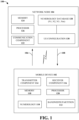
- non-limiting wireless communications system 100 including a mobile device (or UE) 102 and a network 104, for configuring the mobile device 102 for using multiple numerologies, appropriate control channels and partitioned bandwidths, in accordance with one or more embodiments described herein.
- a user equipment (UE) or mobile device 102 e.g., mobile device or other terminology
- a network node 104 e.g., an eNodeB, eNB, network, cell or other terminology.
- the mobile device 102 and/or the network node 104 can be in communication with other mobile devices (not shown) and/or other network nodes (not shown).
- a "link” is a communications channel that connects two or more devices or nodes.
- An uplink (UL 106) refers to a link used for transmission of signals from the mobile device 102 to the network node 104.
- a downlink (DL 108) refers to the link used for transmission of signals from the network node 104 to the mobile device 102. It is noted that although various aspects are discussed with respect to a single mobile device and a single network node, the various aspects discussed herein can be applied to one or more mobile devices and/or one or more network nodes.
- the mobile device 102 can include a numerology component 110, a bandwidth partition component 112, a transmitter component 114, and a receiver component 116. Although illustrated and described with respect to separate components, the transmitter component 114 and the receiver component 116 can be a single transmitter/receiver configured to transmit to and/or receive data to/from the network node 104, other network nodes, and/or other Mobile devices. Through the transmitter component 114 and the receiver component 116, the mobile device 102 can concurrently transmit and receive data, the mobile device 102 can transmit and receive data at different times, or combinations thereof.
- the mobile device 102 can include a control circuit and the processor 120 and the memory 118 can be installed on the control circuit.
- the processor 120 can be configured to execute a program code stored in the memory 118 to perform the various aspects discussed herein and especially with respect to the methodologies illustrated in FIGS. 3-12 .
- the processor 120 can execute the program code in the memory 118 to select numerologies to be used for various transmissions (e.g. transmissions via control channels and data channels) and to apportion partitioned bandwidths for those transmissions.
- the functionality of the numerology component 110 and the bandwidth partition component 112 is described in this disclosure with reference to various methodologies.
- the numerology component 110 contains only one numerology or multiple numerologies.
- numerologies can be added or removed from the numerology component 110.
- Numerology refers to the particular values that are selected for parameters such as subcarrier spacing, symbol times, Fast Fourier Transform (FFT) sizes, etc. for performing orthogonal frequency division multiplexing (OFDM). That is the case in some Long Term Evolution (LTE) complaint mobile phones, wherein only one downlink (DL) numerology is defined for initial access.
- LTE Long Term Evolution
- the numerology is defined to include a 15 KHz subcarrier spacing and the signal and channel to be acquired during initial access are based on 15 KHz numerology.
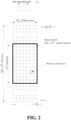
- the OFDM symbols are grouped into resource blocks.
- each resource block would have the length of 5 milliseconds and thus each 1 millisecond transmission time interval (TTI) would transmit two slots (Tslots) of OFDM symbols.
- TTI transmission time interval
- the set of allowed values for N RB DL is given by 3GPP TS 36.104 [6].
- the number of OFDM symbols in a slot depends on the cyclic prefix length and subcarrier spacing configured and is given in Table 6.2.3-1 [reproduced below].
- An antenna port is defined such that the channel over which a symbol on the antenna port is conveyed can be inferred from the channel over which another symbol on the same antenna port is conveyed.
- MBSFN multicast-broadcast single-frequency network
- positioning reference signals positioning reference signals
- UE-specific reference signals associated with PDSCH physical downlink shared channel
- demodulation reference signals associated with EPDCCH enhanced physical downlink control channel
- the network node 104 can include a communication component 122 that can be a transmitter/receiver configured to transmit to and/or receive data from the mobile device 102, other network nodes, and/or other mobile devices. Through the communication component 122, the network node 104 can concurrently transmit and receive data, the network node 104 can transmit and receive data at different times, or combinations thereof.
- the network node 104 can also comprise a memory 124 operatively coupled to a processor 126. The memory 124 can facilitate action to control communication between the network node 104 and the mobile device 102, such that the non-limiting communications system 100 can employ stored protocols and/or algorithms to achieve improved communications in a wireless network as described herein.
- the network node 104 includes a numerology database (or library) 128 and a UE configuration module 130 communicably and/or controllably coupled to the numerology database 128.
- the numerology database 128 includes numerologies N1-Nm that the network node 104 can process.
- one of the numerologies N1-Nm is the default numerology.
- one of the numerologies N1-Nm is the network node 's 104 preferred numerology.
- numerologies can be added or removed from the numerology database 128.
- the UE configuration module 130 is tasked with selecting a proper numerologies for the mobile device 102.
- the UE configuration module 130 is also tasked with selecting proper control channels for the mobile device 102 and informing the mobile device about the selected control channels and their respective numerologies.
- the functionality of the UE configuration module 130 is described in detail below with references to various methodologies of the subject disclosure.
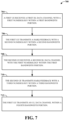
- FIG. 3 illustrates an example, non-limiting methodology by which a UE receives control channel, in accordance with one or more embodiments described herein.
- a UE is configured to use a first numerology for receiving a control channel.
- the UE receives information regarding using a second numerology for receiving a first data channel.
- the UE receives the control channel by using the first numerology.
- the UE receives the first data channel by using the second numerology.
- the first numerology is a default numerology.
- the first numerology is a predefined numerology.
- the first numerology is indicated by a synchronization signal.
- the second numerology is configured by a UE-specific message.
- the second numerology is indicated by the control channel.
- the second numerology can be different for different time intervals.
- the first numerology is cell-specific.
- the control channel and the first data channel are in a same cell.
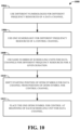
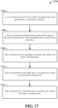
- FIG. 17 illustrates an example, non-limiting methodology by which a UE receives control channel, in accordance with one or more embodiments described herein.
- a UE is configured to use a first numerology for receiving a control channel.
- the UE receives information regarding using a second numerology for transmitting a first data channel.
- the UE receives the control channel by using the first numerology.
- the UE transmits the first data channel by using the second numerology.
- the first numerology is a default numerology.
- the first numerology is a predefined numerology.
- the first numerology is indicated by a synchronization signal.
- the first numerology is configured by a broadcast channel.
- the UE receives a second data channel by using the first numerology.
- the second data channel is a broadcast channel.
- the second data channel is a paging channel.
- the second data channel is a random access response channel.
- the first data channel is for unicast data.
- the first data channel is an UL data channel.
- the control channel schedules the first data channel.
- the second numerology is configured by a radio resource control (RRC) message.
- RRC radio resource control
- the second numerology is configured after the UE enters a connected mode.
- the second numerology is configured by a UE-specific message.
- the second numerology is indicated by the control channel.
- the second numerology can be different for different time intervals.
- the first numerology is cell-specific.
- the control channel and the first data channel are in a same cell.
- the NRs and the 5G networks based on them will have diverse requirements in terms of data rates, latency, and coverage.
- the NRs will support higher data rates, lower latency and higher reliability than current systems, and the devices and methodologies of the present inventions will take advantage of those advanced capabilities.
- the enhanced mobile broadband (eMBB) is expected to support a peak data rate of 20Gbps for downlink and 10Gbps for uplink, and the user experienced data rates expected to be in the order of three times the rate of IMT (international mobile telecommunications)-Advanced.
- IMT international mobile telecommunications
- the ultra reliable and low latency communication (URLLC) systems are expected to provide an ultra-low latency of 0.5 milliseconds for each of UL and DL for user plane latency and a high reliability of 1-10 -5 within 1millisecond).
- massive machine type communication (mMTC) compliant devices will require high connection density (e.g. 1,000,000 devices/km 2 in urban environment), large coverage in harsh environments ([164 dB] maximum coupling loss (MCL)), and extremely long-life battery for low cost devices ([15 years]).
- the 3GPP (3rd Generation Partnership Project) is considering the option is to allow (frequency division multiplexing) FDM/TDM (time division multiplexing) of different types of subframes and/or subbands with different subcarrier numerologies (i.e., different subcarrier-spacing values and correspondingly different OFDM symbol lengths) in a single system bandwidth, where the different subcarrier values are chosen according to the use-case specific requirements.
- a UE may be configured with a single or multiple subcarrier numerologies, possibly depending upon UE capability or category as well as the use cases the UE supports.
- the numerologies used for UL and DL transmission may be different due to different service requirements.
- the network may provide a given numerology with certain bandwidth and certain frequency location within the whole system bandwidth, e.g. 100MHz or 200MHz.
- the bandwidth and frequency location may be adjusted according to certain conditions, e.g. the traffic amount required for each numerology, as shown in a example in FIG. 5 .
- FIG. 5 is an example illustration in which the bandwidth for a given numerology is shown to be contiguous.
- the bandwidth for a given numerology may be non-contiguous (e.g. in frequency domain). Therefore, when a UE is configured with a given numerology, whether or how UE knows the bandwidth partition (e.g. bandwidth and/or frequency location) for that numerology, and thus correctly derives resource allocation for data transmission or reception, requires some consideration. Stated differently, how the UE detects a control channel needs consideration.
- the subject disclosure discloses numerous inventions and alternatives for identifying (or selecting) a message or a channel for carrying information regarding bandwidth partition to a UE.
- information regarding bandwidth partition is signaled by a physical broadcast channel (PBCH) and/or a system information block (SIB).
- PBCH physical broadcast channel
- SIB system information block
- the information regarding bandwidth partition for all numerologies is signaled on a specific numerology. More specifically, preferably the specific numerology is the numerology with which UE detects the corresponding synchronization signal.
- the information is signaled on a per numerology basis, e.g. a numerology would provide its own bandwidth partition in PBCH and/or SIB on the numerology.
- UE assumes a default bandwidth partition on the numerology.
- An example of default bandwidth partition comprises a fixed bandwidth and a frequency location derived from synchronization. For example, the frequency location can be derived from system bandwidth (e.g. the total bandwidth for all numerologies), in addition to synchronization.
- synchronization would determine a first frequency location.
- the first frequency location and an offset value would determine a second frequency location.
- the default bandwidth is located in the second frequency location (e.g. defined by center frequency or starting frequency).
- the offset value is determined from the total system bandwidth.
- the offset value is determined from information carried on MIB or SIB.
- MIB would indicate a first bandwidth partition of a numerology. The first bandwidth partition allows UE to receive some common signaling, e.g. SIB, on the numerology. The common signal would further indicate a second bandwidth partition of the numerology. Thereafter, the following (or subsequent) UE reception would follow the second bandwidth partition.
- the MIB or SIB would indicate a first bandwidth partition of a first numerology.
- the first bandwidth partition allows the UE to receive at least some common signaling, e.g. SIB, on the first numerology.
- the first bandwidth partition would be utilized in the following (or subsequent) communication.
- a UE-specific RRC would further indicate a second bandwidth partition of the numerology. The following UE reception would follow the second bandwidth partition. If the second bandwidth partition of the numerology is absent, UE will continue to use the first bandwidth partition.
- MIB or SIB would indicate a first bandwidth partition of a first numerology.
- the first bandwidth partition allows the UE to receive at least some common signaling, e.g. SIB, on the first numerology.
- the first bandwidth partition would be utilized in the following communication.
- a UE-specific RRC After entering a connected mode, a UE-specific RRC would further configure a second numerology and a second bandwidth partition of the second numerology. The second UE reception would be on the second numerology and would follow the second bandwidth partition.
- a physical control channel is used to carry the information of bandwidth partition.
- the information can be used for a single transmission time interval (TTI).
- TTI transmission time interval
- the information can be used for multiple TTIs. More specifically, preferably the multiple TTIs are within a fixed duration. Alternatively, preferably the multiple TTIs start at predefined timings. Alternatively, preferably the multiple TTIs start a specific number of TTIs (e.g. X TTIs) after receiving the control channel information.
- the bandwidth partition information can be used until new information is received.
- the information is transmitted together with scheduling information. More specifically, preferably the scheduling information is for DL data. Alternatively, preferably the information is transmitted on a specific channel.
- the information includes bandwidth partition for all available numerologies.
- the information includes bandwidth partition for a single numerology.
- the single numerology is the numerology UE is configured with.
- the single numerology is the numerology that the UE decodes a corresponding control channel with.
- the single numerology is indicated in the same control channel.
- the whole system bandwidth is be considered as including potential candidates for a numerology.
- the maximum bandwidth that the UE can receive with the numerology is less than the system bandwidth.
- the network indicates to the UE which resource blocks would be utilized for the data transmission with the numerology that the UE is configured with.
- the UE can ignore a scheduling request if the total resource allocated for the UE is larger than what UE is able to receive, or if the bandwidth indicated is larger than what the UE is able to receive.
- the UE can receive data according to a scheduling request even if the total resource allocated for the UE is larger than what UE is able to receive, or if the bandwidth indicated is larger than what UE is able to receive.
- the UE would only receive the data within the maximum bandwidth that can be received by the UE, and would not receive the data outside the maximum bandwidth.
- the UE may need a way to determine which part of the data includes the valid resource to be counted within the maximum bandwidth. In one example, UE counts the maximum bandwidth starting from the resource block with lowest frequency within the resource allocation. In another example, UE counts the maximum bandwidth starting from the resource block with highest frequency within the resource allocation.
- a UE is configured with a first numerology for a control channel and is informed to use a second numerology for a data channel.
- the data channel is a unicast data channel.
- the second numerology is different form the first numerology.
- the first numerology is a default/predefined numerology.
- the first numerology is a cell-specific numerology.
- the first numerology is the largest numerology.
- the first numerology is indicated on a broadcast channel.
- the broadcast channel does not have an associated control channel.
- the broadcast channel can be transmitted with a fixed or predefined numerology.
- the broadcast channel does have an associated control channel, and the associated control channel is transmitted with a default/predefined numerology.
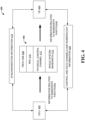
- FIG. 4 summarizes the four alternative methodologies of the subject disclosure discussed above for transmitting information related to bandwidth partition from the cell 402 to the UE 404.
- the four methodologies 406 are shown for carrying the bandwidth partition information from the cell 402 to the UE 404.
- the four methodologies 406 include signaling by way of PBCH and/or SIB 408, signaling by way of RRC 410, using a physical control channel 412 to carry information related to bandwidth partition and providing information about the bandwidth for the whole system bandwidth 414.
- the cell 402 and the UE 404 also exchange synchronization information 418 and information about data channels and control channels 420.
- the synchronization information 418 and the information about data/control channels 420 may include numerologies related information or indications.
- the first numerology is indicated by a synchronization channel. More specifically, preferably a broadcast channel is transmitted with the first numerology.
- the second numerology is UE specifically configured.
- the second numerology is configured after UE entering connected mode.
- the second numerology is indicated by a control channel.
- the control channel is associated with a corresponding unicast data channel which is transmitted with the second numerology.
- the second numerology is applied to the unicast data channel associated with the control channel. More specifically, preferably "associated" means the control channel providing scheduling information for the data channel.
- the second numerology is selected according to a service requirement for the unicast data channel.
- control channel can be used to schedule unicast data.
- control channel can be used to schedule common data, e.g. broadcast information, paging information or random access response.
- control channel and the data channel are multiplexed in the time domain.
- a first numerology is configured for control channel reception. Meaning that the UE tries to decode the control channel with the first numerology. If a control channel is detected and there is a corresponding data channel, the control channel further indicates a second numerology for data channel reception (DL) or transmission (UL).
- the second numerology may be the same as the first numerology or different from the first numerology.
- a default numerology can be defined for a certain type of data channel so that extra indication of numerologies may not be needed for that type of data channel. By doing so, numerologies for data communication can be adapted dynamically to fulfill different requirements while control channel reception can be kept the same to avoid increase in complexity or latency of decoding.
- FIG. 6 illustrates an example methodology in which control channel that is controlled with a specific numerology schedules a data channel to be controlled with a different numerology.
- different frequency regions for data channel scheduling are associated with different control channel candidates. If a control channel candidate is successfully decoded, the corresponding data channel would be scheduled within the associated frequency region. More specifically, preferably the control channel would indicate which resource within the associated frequency region would be used for the data channel.
- a frequency region is a portion of a system bandwidth of a cell.
- UE is configured with the locations/ranges of several frequency regions.
- the frequency region is implicitly derived from the system bandwidth of the cell. In the following, how the association is done is described.
- a control channel candidate within a first frequency region would be associated with the same first frequency region.
- an index of a control channel candidate would be associated with an index of a frequency region. More specifically, preferably the index of the control channel is an index of a control channel element. More specifically, preferably the index of the frequency region follows a frequency order of the frequency region. Preferably, the index of the associated frequency region is derived from the index of the corresponding control channel candidate. More specifically, preferably an equation is used to derive the index. Alternatively, preferably a look-up table is used to derive the index. Preferably, a frequency region closest to a control channel candidate in frequency domain would be associated with the control channel candidate. Preferably, a control channel candidate would determine a frequency location of a frequency region, e.g. the center of the frequency location, and the frequency location would have a configurable or predefined bandwidth.
- a UE is configured with a first numerology for DL data channel and a second numerology for UL data channel and a third numerology for control channel.
- the third numerology is derived from the first numerology and the second numerology. More specifically, preferably the third numerology is the smaller one between the first numerology and the second numerology. Alternatively, preferably the third numerology is the larger one between the first numerology and the second numerology. Preferably, the third numerology is different from the first numerology and the second numerology. Preferably, the third numerology is a default or predefined numerology.
- the various aspects described above can be applied to or implemented in exemplary wireless communication systems and devices described below.
- the various aspects are described mainly in the context of the 3GPP architecture reference model. However, it is understood that with the disclosed information, one skilled in the art could easily adapt for use and implement aspects of the invention in a 3GPP2 network architecture as well as in other network architectures.
- the exemplary wireless communication systems and devices described in this disclosure employ a wireless communication system, supporting a broadcast service. Wireless communication systems are widely deployed to provide various types of communication such as voice, data, and so on.
- CDMA code division multiple access
- TDMA time division multiple access
- OFDMA orthogonal frequency division multiple access
- 3GPP LTE Long Term Evolution
- 3GPP LTE-A Long Term Evolution Advanced
- 3GPP2 UMB Ultra Mobile Broadband
- WiMax Wireless Fidelity
- the first numerology and the second numerology are the same.
- a second UE receives a second DL data channel with the first numerology within the first bandwidth portion.
- the second UE transmits a HARQ feedback with a third numerology corresponding to data in the second downlink data channel within a third bandwidth portion.
- the second numerology and the third numerology are different.
- the second bandwidth portion and the third bandwidth portion do not overlap.
- the third bandwidth portion is located in the first bandwidth portion.
- a location of the first bandwidth portion is configured (or programmed or determined).
- a resource allocation field allocates the first DL data channel within the first bandwidth portion.
- a resource allocation field allocates the first DL data channel cannot schedule data outside the first bandwidth portion.
- the first bandwidth portion is the maximum resource that can be allocated for the first downlink data channel.
- a resource used to carry the HARQ feedback is fixed.
- a resource used to carry the HARQ feedback is configured.
- a resource used to carry the HARQ feedback is derived from the first downlink control channel information.
- a relative location of resource used to carry the HARQ feedback within the second bandwidth portion is fixed.
- a relative location of resource used to carry the HARQ feedback within the second bandwidth portion is configured.
- a relative location of resource used to carry the HARQ feedback within the second bandwidth portion is derived from the first downlink control channel.
- the first numerology and the second numerology are different.
- the first numerology and the third numerology are the different.
- the second bandwidth portion and the third bandwidth portion do not overlap.
- the second bandwidth portion is located in the first bandwidth portion.
- the third bandwidth portion is located in the first bandwidth portion.
- the second bandwidth portion and the first bandwidth portion are multiplexed in time domain.
- the third bandwidth portion and the first bandwidth portion are multiplexed in time domain.
- numerology refers to subcarrier spacing and/or cyclic prefix length.
- a first numerology is configured for DL control/data
- a second numerology is configured for UL control/data.
- a first numerology is configured for DL control, DL data and uplink control and a second numerology configured for uplink data.
- a first numerology is configured for DL data and uplink control, a second numerology configured for uplink data and a third numerology configured for DL control.
- the UL control information other than HARQ feedback includes channel state information.
- UL control information other than HARQ feedback is a scheduling request.
- the UE realizes the location of the third bandwidth portion according to a downlink control channel associated with the downlink data.
- the UE realizes the location of the third bandwidth portion according to a configuration.
- the second bandwidth portion is located in a configured location of the third bandwidth portion.
- the second bandwidth portion is located in a configured location of the third bandwidth portion which is derived from an associated downlink control channel.
- the location is derived from a resource occupied by a downlink control channel.
- the third bandwidth portion and second bandwidth portion are multiplexed in time domain.
- a resource for transmitting the HARQ feedback is selected from resources within the second bandwidth portion.
- a resource for transmitting the HARQ feedback is selected according to a predefined rule.
- a resource for transmitting the HARQ feedback is selected according to a configuration.
- a resource for transmitting the HARQ feedback is indicated by a downlink control channel.
- the first bandwidth portion and the second bandwidth portion do not overlap in the frequency domain.
- a first UE transmits UL data on the first bandwidth portion and transmits HARQ feedback on the second bandwidth portion, with the same numerology.
- a first UE transmits UL data on the first bandwidth portion and transmits HARQ feedback on the second bandwidth portion, with different numerologies.
- the first bandwidth portion is indicated by another signaling.
- the resource allocated for UL data is a subset of the first bandwidth portion.
- the first bandwidth portion and the third bandwidth portion are independently signaled.
- the first bandwidth portion and the third bandwidth portion are different.
- the base station operates in TDD mode.
- FIG. 8 illustrates an example of downlink and uplink bandwidth partition.
- the DL data channel and the corresponding HARQ feedback channel may use different numerologies.
- a subset of UL numerologies can be used for HARQ feedback transmission. Meaning that not all UL numerologies used by a base station can be used for HARQ feedback transmission for a DL data channel with a given numerology.
- the subset of UL numerologies includes numerologies with subcarrier spacing larger than or equal to a subcarrier spacing of a numerology used for DL data.
- the subset of UL numerology includes numerologies with subcarrier spacing twice of or equal to a subcarrier spacing of a numerology used for DL data.
- the subset of UL numerology is numerologies with subcarrier spacing half of or equal to a subcarrier spacing of a numerology used for DL data.
- the subset of UL numerology is numerologies with subcarrier spacing smaller than or equal to a subcarrier spacing of a numerology used for DL data.
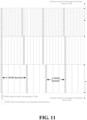
- FIG. 9 illustrates example relationships between bandwidth portions for DL data and corresponding bandwidth portions for HARQ feedbacks.
- edge(s) of some bandwidth portions for HARQ feedbacks are aligned with edge(s) of bandwidth portions for DL data.
- edge(s) of some bandwidth portions for HARQ feedbacks are not aligned with edge(s) of bandwidth portions for DL data.
- there can be multiple bandwidth portions for HARQ feedbacks which are transmitted with the same numerology for a given instance, and which correspond to DL data channels with different numerologies.
- bandwidth portion for downlink data and bandwidth portion for HARQ feedback
- the frequency separation between DL data and HARQ feedback can be minimized, so as to avoid any RF retune between DL data transmission and HARQ feedback transmission.
- the bandwidth portion mentioned in this disclosure relates to a set of resources in a frequency domain which may be described by their respective location(s) and bandwidth(s).
- the required control signaling overhead may be similar for two numerologies, e.g. when same or similar number of UEs are scheduled to use each of the two numerologies.
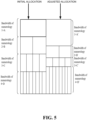
- the granularity (or preset increment) of the number of OFDM symbols for a frequency resource for a data channel with X kHz subcarrier spacing is 4, 8, 12 OFDM symbols. That is restrictive and wasteful when compared with the variant control overhead that is actually/really required.
- inventions of the subject disclosure provide solutions for using only the needed or desired number of OFDM symbols are used for a control channel, e.g. using only 2 OFDM symbols out of the 4 available ones.
- the starting position of the OFDM symbols for numerology of the data channel, within a given time period, is shifted by one OFDM symbol in comparison with the OFDM symbol for the numerology of the control channel.
- the one OFDM symbol for the numerology for the control channel is placed at the beginning of each scheduling unit of the data channel.
- each scheduling unit of the data channel's different frequency resources would comprise different number of OFDM symbols corresponding with the different subcarrier spacings for the data channel.
- FIG. 12 illustrates an example alternative structure in which the OFDM symbols are arranged.
- the number of scheduling units for a data channel e.g. TTI, slot, or mini slot
- the difference between the number of scheduling units used by two frequency resources can be in the order of power of two multiple.
- the starting position of OFDM symbols for numerology of data within a given period, would be shifted by one from the OFDM symbol for control.
- the scheduling units of the data channel for different frequency resources would comprise the same number of OFDM symbols corresponding to subcarrier spacings for the data channel.
- control channel on different OFDM symbols would be used for different beams.
- different base station/TRP beams would be applied for the 4 OFDM symbols.
- the four symbols comprise the same control information. In another embodiment, the four symbols comprise different control information.
- FIG. 18 illustrates an example wireless communication system in which two UEs are interacting with the network node, in accordance with one or more embodiments described herein.
- Components and functions of the network node 104 and the mobile device 102 have been described herein with reference to FIG.1 .
- Mobile device 1812 has similar components and functions as the mobile device 102.
- the mobile device 102 is communicatively coupled with the network node 104 by way of the uplink (UL) 106 and the downlink (DL) 108. As illustrated in FIGS. 3 , 7 and 17 , at least the following communications occur between the network node 104 and the mobile devices 102, 1812.
- Access terminal (AT) 1316 is in communication with antennas 1304 and 1306, where antennas 1304 and 1306 transmit information to access terminal (AT) 1320 over forward link 1322 (e.g., DL) and receive information from access terminal (AT) 1320 over reverse link 1324 (e.g., UL).
- communication links 1316, 1318, 1322, and 1324 may use different frequency for communication.
- forward link 1316 may use a different frequency than that used by reverse link 1318.
- antenna groups each are designed to communicate to access terminals in a sector of the areas covered by access network 1300.
- the transmitting antennas of access network 1300 may utilize beamforming in order to improve the signal-to-noise ratio of forward links for the different access terminals 1314 and 1320. Also, an access network using beamforming to transmit to access terminals scattered randomly through its coverage normally causes less interference to access terminals in neighboring cells than an access network transmitting through a single antenna to all its access terminals.
- An access network may be a fixed station or base station used for communicating with the terminals and may also be referred to as an access point, a Node B, a base station, an enhanced base station, an eNodeB, or some other terminology.
- An access terminal may also be called user equipment (UE), a wireless communication device, terminal, access terminal or some other terminology.
- FIG. 14 illustrates a simplified block diagram of an embodiment a MIMO system 1400 that includes of a transmitter system 1402 (also known as the access network) and a receiver system 1404 (also known as access terminal (AT) or user equipment (UE)) in accordance with one or more embodiments described herein.
- a transmitter system 1402 also known as the access network
- a receiver system 1404 also known as access terminal (AT) or user equipment (UE)
- traffic data for a number of data streams is provided from a data source 1406 to a transmit (TX) data processor 1408.
- TX transmit
- each data stream is transmitted over a respective transmit antenna.
- TX data processor 1408 formats, codes, and interleaves the traffic data for each data stream based on a particular coding scheme selected for that data stream to provide coded data.
- the coded data for each data stream may be multiplexed with pilot data using OFDM techniques.
- the pilot data is typically a known data pattern that is processed in a known manner and may be used at the receiver system to estimate the channel response.
- the multiplexed pilot and coded data for each data stream is then modulated (e.g., symbol mapped) based on a particular modulation scheme (e.g., BPSK, QPSK, M-PSK, or M-QAM) selected for that data stream to provide modulation symbols.
- the data rate, coding, and modulation for each data stream may be determined by instructions performed by processor 1410.
- TX MIMO processor 1412 may further process the modulation symbols (e.g., for OFDM).
- TX MIMO processor 1412 then provides N T modulation symbol streams to N T transmitters (TMTR) 1414a through 1414t.
- TMTR TX MIMO processor 1412 applies beamforming weights to the symbols of the data streams and to the antenna from which the symbol is being transmitted.
- the transmitted modulated signals are received by N R antennas 1418a through 1418r and the received signal from each antenna 1418 is provided to a respective receiver (RCVR) 1420a through 1420r.
- Each receiver 1420 conditions (e.g., filters, amplifies, and downconverts) a respective received signal, digitizes the conditioned signal to provide samples, and further processes the samples to provide a corresponding "received" symbol stream.
- the program code can be executed to perform the techniques illustrated in FIGS. 3-12 , 17 , and 18 .
- the communications device 1500 can receive signals input by a user through the input device 1502, such as a keyboard or keypad, and can output images and sounds through the output device 1504, such as a monitor or speakers.
- the transceiver 1514 is used to receive and transmit wireless signals, delivering received signals to the control circuit 1506, and outputting signals generated by the control circuit 1506 wirelessly.
- FIG. 16 is a simplified block diagram of the program code 1512 shown in FIG. 15 , in accordance with one or more embodiments described herein.
- the program code 1512 includes an application layer 1600, a Layer 3 portion 1602, and a Layer 2 portion 1604, and is coupled to a Layer 1 portion 1606.
- the Layer 3 portion 1602 generally performs radio resource control.
- the Layer 2 portion 1604 generally performs link control.
- the Layer 1 portion 1606 generally performs physical connections.
- the Layer 2 portion 1604 may include a Radio Link Control (RLC) layer and a Medium Access Control (MAC) layer.
- the Layer 3 portion 1602 may include a Radio Resource Control (RRC) layer.
- RLC Radio Link Control
- MAC Medium Access Control
- RRC Radio Resource Control
Landscapes
- Engineering & Computer Science (AREA)
- Signal Processing (AREA)
- Computer Networks & Wireless Communication (AREA)
- Physics & Mathematics (AREA)
- Mathematical Physics (AREA)
- Mobile Radio Communication Systems (AREA)
Claims (9)
- Verfahren, umfassend:Konfigurieren, durch eine Benutzerausrüstung, im Folgenden auch als UE bezeichnet, eine erste Numerologie zum Empfangen eines Steuerkanals (304; 1704) zu verwenden;Empfangen, durch die UE, von Informationen bezüglich der Verwendung einer zweiten Numerologie zum Empfangen oder Senden eines ersten Datenkanals (306; 1706), wobei die zweite Numerologie durch den Steuerkanal angegeben wird;Empfangen, durch die UE, des Steuerkanals unter Verwendung der ersten Numerologie (308; 1708), undEmpfangen oder Senden, durch die UE, des ersten Datenkanals unter Verwendung der zweiten Numerologie (310; 1710),dadurch gekennzeichnet, dassder Steuerkanal den ersten Datenkanal zeitlich plant.
- Verfahren nach Anspruch 1, wobei die erste Numerologie eine vordefinierte Numerologie ist.
- Verfahren nach Anspruch 1 oder 2, wobei die UE einen zweiten Datenkanal unter Verwendung der ersten Numerologie (312; 1712) empfängt.
- Verfahren nach einem der Ansprüche 1 bis 3, wobei der zweite Datenkanal ein gemeinsamer Datenkanal oder ein Rundsendekanal ist.
- Verfahren nach einem der Ansprüche 1 bis 4, wobei der erste Datenkanal für Unicast-Daten ist.
- Verfahren nach einem der Ansprüche 1 bis 5, wobei die zweite Numerologie durch eine Funkressourcensteuerungs- , im Folgenden auch als RRC bezeichnet, -Nachricht konfiguriert wird.
- Verfahren nach einem der Ansprüche 1 bis 6, wobei der Steuerkanal und der erste Datenkanal in einer gleichen Zelle sind.
- Verfahren nach einem der Ansprüche 1 bis 7, wobei die zweite Numerologie für unterschiedliche Zeitintervalle unterschiedlich ist.
- Benutzerausrüstung, im Folgenden auch als UE bezeichnet, zum Durchführen einer Direktzugriffsprozedur, umfassend:eine Steuerschaltung (1506);einen Prozessor (1508), der in der Steuerschaltung (1506) installiert ist; undeinen Speicher (1510), der in der Steuerschaltung (1506) installiert und betriebsfähig mit dem Prozessor (1508) gekoppelt ist;dadurch gekennzeichnet, dassder Prozessor (1508) konfiguriert ist, um einen Programmcode (1512) auszuführen, der in dem Speicher (1510) gespeichert ist, um die in einem der vorhergehenden Ansprüche definierten Verfahrensschritte durchzuführen.
Applications Claiming Priority (3)
| Application Number | Priority Date | Filing Date | Title |
|---|---|---|---|
| US201662402292P | 2016-09-30 | 2016-09-30 | |
| US201662414341P | 2016-10-28 | 2016-10-28 | |
| US201662421572P | 2016-11-14 | 2016-11-14 |
Publications (3)
| Publication Number | Publication Date |
|---|---|
| EP3301848A2 EP3301848A2 (de) | 2018-04-04 |
| EP3301848A3 EP3301848A3 (de) | 2018-06-20 |
| EP3301848B1 true EP3301848B1 (de) | 2025-04-02 |
Family
ID=60019706
Family Applications (1)
| Application Number | Title | Priority Date | Filing Date |
|---|---|---|---|
| EP17194081.0A Active EP3301848B1 (de) | 2016-09-30 | 2017-09-29 | Verfahren und vorrichtung zum empfangen eines steuerkanals für mehrere nummerierungen in einem drahtloskommunikationssystem |
Country Status (7)
| Country | Link |
|---|---|
| US (1) | US10805907B2 (de) |
| EP (1) | EP3301848B1 (de) |
| JP (1) | JP6594940B2 (de) |
| KR (1) | KR102110639B1 (de) |
| CN (1) | CN107889253B (de) |
| ES (1) | ES3024332T3 (de) |
| TW (1) | TWI672016B (de) |
Families Citing this family (30)
| Publication number | Priority date | Publication date | Assignee | Title |
|---|---|---|---|---|
| CN119363307A (zh) * | 2016-09-30 | 2025-01-24 | 诺基亚技术有限公司 | 用于子帧布置的装置和方法 |
| US11172444B2 (en) * | 2016-10-10 | 2021-11-09 | Qualcomm Incorporated | Techniques for power control and management |
| US10355803B2 (en) | 2016-10-24 | 2019-07-16 | Qualcomm Incorporated | Multiplexing reference signals with scalable numerology for new radio (NR) networks |
| CN109891988B (zh) * | 2016-10-27 | 2022-08-09 | 株式会社Kt | 用于在下一代无线网络中调度上行链路信号和下行链路数据信道的方法和设备 |
| KR20180046358A (ko) * | 2016-10-27 | 2018-05-08 | 주식회사 케이티 | 차세대 무선 액세스망을 위한 스케줄링 방법 및 장치 |
| US10334533B2 (en) * | 2016-11-02 | 2019-06-25 | At&T Intellectual Property I, L.P. | Non-orthogonal design for channel state information reference signals for a 5G air interface or other next generation network interfaces |
| US20180160405A1 (en) * | 2016-12-02 | 2018-06-07 | Qualcomm Incorporated | Rate matching and signaling |
| CN108271257B (zh) * | 2016-12-31 | 2021-07-09 | 华为技术有限公司 | 一种资源配置方法及装置 |
| CN108282870B (zh) * | 2017-01-06 | 2021-04-20 | 华为技术有限公司 | 一种资源指示方法、用户设备及网络设备 |
| US10237032B2 (en) | 2017-01-06 | 2019-03-19 | At&T Intellectual Property I, L.P. | Adaptive channel state information reference signal configurations for a 5G wireless communication network or other next generation network |
| US10320512B2 (en) | 2017-01-08 | 2019-06-11 | At&T Intellectual Property I, L.P. | Interference cancelation for 5G or other next generation network |
| US10506630B2 (en) * | 2017-03-24 | 2019-12-10 | Kt Corporation | Method for scheduling downlink data channel or uplink data channel in next radio network and apparatus thereof |
| US10805941B2 (en) * | 2017-03-24 | 2020-10-13 | Sharp Kabushiki Kaisha | Radio resource control (RRC) messages for enhanced scheduling request |
| US10917278B2 (en) * | 2017-04-28 | 2021-02-09 | Nokia Technologies Oy | Frequency-domain transmitters and receivers which adapt to different subcarrier spacing configurations |
| CN109587799B (zh) * | 2017-09-29 | 2023-07-18 | 华为技术有限公司 | 一种信息传输方法及装置 |
| WO2019083702A1 (en) * | 2017-10-23 | 2019-05-02 | Kyocera Corporation | DATA TRANSMISSION WITH MULTIPLE NUMEROLOGIES FOR MULTIPLE DEVICES HAVING CONTROL INFORMATION DEPENDENT ON A COMMON GEOGRAPHIC LOCATION |
| CN109661031B (zh) * | 2017-11-17 | 2020-06-16 | 华为技术有限公司 | 传输寻呼消息的方法、终端设备和网络设备 |
| US10862613B2 (en) | 2018-02-01 | 2020-12-08 | T-Mobile Usa, Inc. | Dynamic numerology based on services |
| US11259351B2 (en) * | 2018-04-19 | 2022-02-22 | Qualcomm Incorporated | EN-DC time division multiplexing and carrier aggregation |
| CN110461003A (zh) * | 2018-05-07 | 2019-11-15 | 华为技术有限公司 | 一种带宽部分bwp的配置信息的确定方法及装置 |
| BR112020022864A2 (pt) * | 2018-05-10 | 2021-02-23 | Ntt Docomo, Inc. | terminal de usuário |
| CN110635871B (zh) * | 2018-06-22 | 2021-08-31 | 华为技术有限公司 | 生成混合自动重传请求harq信息的方法和装置 |
| CN110635870B (zh) * | 2018-06-22 | 2021-05-18 | 华为技术有限公司 | 生成混合自动重传请求harq信息的方法和装置 |
| WO2020010493A1 (en) * | 2018-07-09 | 2020-01-16 | Nokia Shanghai Bell Co., Ltd. | Harq solutions to support multiple active bandwidth parts |
| US11832240B2 (en) * | 2018-09-26 | 2023-11-28 | Beijing Xiaomi Mobile Software Co., Ltd. | Method and device for sidelink communication |
| KR102520124B1 (ko) * | 2019-03-07 | 2023-04-10 | 애플 인크. | 혼합된 뉴머롤로지들을 갖는 주파수 도메인 다중화된(fdmed) dl 채널들로 인한 인터-캐리어 간섭(ici)의 완화 |
| US12342397B2 (en) | 2019-07-23 | 2025-06-24 | Beijing Xiaomi Mobile Software Co., Ltd. | Direct connection communication method and apparatus |
| US11711250B2 (en) | 2020-03-13 | 2023-07-25 | Telefonaktiebolaget Lm Ericsson (Publ) | Multi-numerology frame structure for NR operation in mm-wave frequency bands |
| KR102635797B1 (ko) * | 2020-08-06 | 2024-02-13 | 아서스테크 컴퓨터 인코포레이션 | 무선 통신 시스템의 자원 할당 방법 및 장치 |
| CN115701191A (zh) * | 2021-07-23 | 2023-02-07 | 华为技术有限公司 | 一种配置方法及通信装置 |
Citations (1)
| Publication number | Priority date | Publication date | Assignee | Title |
|---|---|---|---|---|
| US20070195690A1 (en) * | 2006-02-21 | 2007-08-23 | Qualcomm Incorporated | Flexible time-frequency multiplexing structure for wireless communication |
Family Cites Families (27)
| Publication number | Priority date | Publication date | Assignee | Title |
|---|---|---|---|---|
| US6526065B1 (en) * | 1999-01-21 | 2003-02-25 | Industrial Technology Research Institute | Code management system and method for CDMA communication networks |
| US7701844B2 (en) * | 2005-02-09 | 2010-04-20 | Interdigital Technology Corporation | Method and apparatus for recognizing radio link failures associated with HSUPA and HSDPA channels |
| US7827593B2 (en) * | 2005-06-29 | 2010-11-02 | Intel Corporation | Methods, apparatuses, and systems for the dynamic evaluation and delegation of network access control |
| US8477593B2 (en) * | 2006-07-28 | 2013-07-02 | Qualcomm Incorporated | Method and apparatus for sending signaling for data transmission in a wireless communication system |
| WO2008125905A2 (en) | 2006-08-08 | 2008-10-23 | Nortel Networks Limited | Method and system for wireless communication in multiple operating environments |
| KR100880885B1 (ko) * | 2006-12-31 | 2009-01-30 | 포스데이타 주식회사 | 무선통신 시스템에서의 상향링크 신호 전송 장치 및 방법 |
| EP1944896A1 (de) | 2007-01-09 | 2008-07-16 | Matsushita Electric Industrial Co., Ltd. | Konfiguration von Steuerkanälen in einem mobilen Kommunikationssystem |
| US9668265B2 (en) * | 2008-03-28 | 2017-05-30 | Qualcomm Inc. | Technique for mitigating interference in a celllar wireless communication netwok |
| EP3399821B1 (de) * | 2009-03-12 | 2024-02-28 | Sun Patent Trust | Funkendgerät sowie verfahren zum empfangen eines kontrollkanals in abwärtsrichtung |
| US8433251B2 (en) * | 2009-09-28 | 2013-04-30 | Qualcomm Incorporated | Control information signaling |
| KR101676013B1 (ko) | 2010-05-03 | 2016-11-14 | 삼성전자주식회사 | 무선 통신 시스템에서 제어 채널을 재설정하는 방법 및 장치 |
| US9160513B2 (en) * | 2011-07-28 | 2015-10-13 | Qualcomm Incorporated | Method and apparatus for signaling control data of aggregated carriers |
| DK2901793T3 (en) * | 2012-09-27 | 2017-02-13 | ERICSSON TELEFON AB L M (publ) | METHODS AND SYSTEMS FOR TDD-PUCCH-HARQ RESOURCE ALLOCATION FOR ENHANCED PHYSICAL DOWNLINK CONTROL CHANNEL (EPDCCH) |
| WO2014060037A1 (en) | 2012-10-18 | 2014-04-24 | Nokia Solutions And Networks Oy | Communication of control information and data in frames |
| WO2016130175A1 (en) * | 2015-02-11 | 2016-08-18 | Intel IP Corporation | Device, system and method employing unified flexible 5g air interface |
| CN107925536B (zh) * | 2015-07-06 | 2021-10-29 | 瑞典爱立信有限公司 | 用于无线系统中数据传送的资源分配 |
| WO2017018758A1 (ko) * | 2015-07-24 | 2017-02-02 | 엘지전자 주식회사 | 하향링크 제어 정보 수신 방법 및 사용자기기와, 하향링크 제어 정보 전송 방법 및 기지국 |
| US10045345B2 (en) * | 2015-11-06 | 2018-08-07 | Huawei Technologies Co., Ltd. | Systems and methods for self-contained air interface partitions |
| US10225065B2 (en) * | 2015-12-18 | 2019-03-05 | Qualcomm Incorporated | Common control channel subband design and signaling |
| EP4187832A1 (de) * | 2016-01-29 | 2023-05-31 | Ntt Docomo, Inc. | Benutzerendgerät, funkbasisstation und funkkommunikationsverfahren |
| US10638474B2 (en) * | 2016-04-21 | 2020-04-28 | Qualcomm Incorporated | Different numerology for signal transmission |
| US11764914B2 (en) * | 2016-05-09 | 2023-09-19 | Qualcomm Incorporated | Numerology dependent signal transmission |
| WO2017206187A1 (zh) * | 2016-06-03 | 2017-12-07 | 广东欧珀移动通信有限公司 | 传输数据的方法和装置 |
| US10412632B2 (en) * | 2016-08-12 | 2019-09-10 | Qualcomm Incorporated | Adaptive numerology for URLLC |
| JP6877296B2 (ja) * | 2016-08-12 | 2021-05-26 | 華碩電腦股▲ふん▼有限公司 | 無線通信システムにおける測定のためのヌメロロジ帯域幅を決定する方法及び装置 |
| US10887941B2 (en) * | 2016-08-18 | 2021-01-05 | Qualcomm Incorporated | Retaining access to a shared radio frequency spectrum band during an uplink control portion of a transmission structure |
| US11252717B2 (en) * | 2016-09-02 | 2022-02-15 | Huawei Technologies Co., Ltd. | Co-existence of latency tolerant and low latency communications |
-
2017
- 2017-09-29 KR KR1020170127715A patent/KR102110639B1/ko active Active
- 2017-09-29 TW TW106133831A patent/TWI672016B/zh active
- 2017-09-29 CN CN201710910614.7A patent/CN107889253B/zh active Active
- 2017-09-29 US US15/721,136 patent/US10805907B2/en active Active
- 2017-09-29 JP JP2017189915A patent/JP6594940B2/ja active Active
- 2017-09-29 EP EP17194081.0A patent/EP3301848B1/de active Active
- 2017-09-29 ES ES17194081T patent/ES3024332T3/es active Active
Patent Citations (1)
| Publication number | Priority date | Publication date | Assignee | Title |
|---|---|---|---|---|
| US20070195690A1 (en) * | 2006-02-21 | 2007-08-23 | Qualcomm Incorporated | Flexible time-frequency multiplexing structure for wireless communication |
Non-Patent Citations (1)
| Title |
|---|
| INTEL CORPORATION: "On Layer 1 design and procedures for NB-IoT downlink", vol. RAN WG1, no. Anaheim, USA; 20151115 - 20151122, 7 November 2015 (2015-11-07), XP051022356, Retrieved from the Internet <URL:http://www.3gpp.org/ftp/tsg_ran/WG1_RL1/TSGR1_83/Docs/> [retrieved on 20151107] * |
Also Published As
| Publication number | Publication date |
|---|---|
| JP2018061247A (ja) | 2018-04-12 |
| TWI672016B (zh) | 2019-09-11 |
| EP3301848A2 (de) | 2018-04-04 |
| KR20180036618A (ko) | 2018-04-09 |
| US10805907B2 (en) | 2020-10-13 |
| EP3301848A3 (de) | 2018-06-20 |
| ES3024332T3 (en) | 2025-06-04 |
| US20180098312A1 (en) | 2018-04-05 |
| CN107889253B (zh) | 2021-03-23 |
| TW201815111A (zh) | 2018-04-16 |
| JP6594940B2 (ja) | 2019-10-23 |
| CN107889253A (zh) | 2018-04-06 |
| KR102110639B1 (ko) | 2020-05-14 |
Similar Documents
| Publication | Publication Date | Title |
|---|---|---|
| EP3301848B1 (de) | Verfahren und vorrichtung zum empfangen eines steuerkanals für mehrere nummerierungen in einem drahtloskommunikationssystem | |
| US12446010B2 (en) | Method and apparatus of operation considering bandwidth part in next generation wireless communication system | |
| EP3277046B1 (de) | Verfahren und vorrichtung für ein drahtloskommunikationssystem zur ermöglichung einer erstzugangskommunikation zwischen einer mobilen vorrichtung und einer netzwerkzelle mit unterstützung mehrerer numerologien | |
| CN111587554B (zh) | 无线通信系统的信道复用方法和复用的信道传输方法及使用该方法的设备 | |
| US9826540B1 (en) | Uplink transmission in shortened transmission time intervals in a wireless communication system | |
| US20210004038A1 (en) | Method and apparatus for receiving control channel for multiple numerologies in a wireless communications system | |
| CN107196751B (zh) | 用于在蜂窝通信系统中控制通信装置的方法和设备 | |
| CN111049633B (zh) | 在无线通信系统中传输用于终端的控制信道的方法和装置 | |
| CN107534976B (zh) | 用于发送和接收数据信道的方法以及lc设备 | |
| TWI816065B (zh) | 供無線通訊系統中的使用者設備使用的方法、無線通訊系統中的使用者設備及供無線通訊系統中的基地台使用的方法 | |
| CN107949999B (zh) | 用于在通信网络中传送参考信号的方法和设备 | |
| CN116669207A (zh) | 在无线通信系统中发送和接收共享信道的方法以及支持该方法的装置 | |
| US10701710B2 (en) | Method and apparatus for multiplexing transmissions for different services in a wireless communication system | |
| CN119450730A (zh) | 无线通信系统中接收物理控制信道的方法及使用其的设备 | |
| CN118612881A (zh) | 在未授权频带中执行传输的信道接入方法及使用其的设备 | |
| CN112655263B (zh) | 在非许可频带中进行无线通信的方法和装置 | |
| JP2020074536A (ja) | 通信ネットワークにおける参照信号 | |
| KR20250049454A (ko) | 무선 통신 시스템에서 데이터 송수신 방법, 장치 및 시스템 |
Legal Events
| Date | Code | Title | Description |
|---|---|---|---|
| PUAI | Public reference made under article 153(3) epc to a published international application that has entered the european phase |
Free format text: ORIGINAL CODE: 0009012 |
|
| STAA | Information on the status of an ep patent application or granted ep patent |
Free format text: STATUS: THE APPLICATION HAS BEEN PUBLISHED |
|
| AK | Designated contracting states |
Kind code of ref document: A2 Designated state(s): AL AT BE BG CH CY CZ DE DK EE ES FI FR GB GR HR HU IE IS IT LI LT LU LV MC MK MT NL NO PL PT RO RS SE SI SK SM TR |
|
| AX | Request for extension of the european patent |
Extension state: BA ME |
|
| PUAL | Search report despatched |
Free format text: ORIGINAL CODE: 0009013 |
|
| AK | Designated contracting states |
Kind code of ref document: A3 Designated state(s): AL AT BE BG CH CY CZ DE DK EE ES FI FR GB GR HR HU IE IS IT LI LT LU LV MC MK MT NL NO PL PT RO RS SE SI SK SM TR |
|
| AX | Request for extension of the european patent |
Extension state: BA ME |
|
| RIC1 | Information provided on ipc code assigned before grant |
Ipc: H04L 5/00 20060101AFI20180517BHEP |
|
| STAA | Information on the status of an ep patent application or granted ep patent |
Free format text: STATUS: REQUEST FOR EXAMINATION WAS MADE |
|
| 17P | Request for examination filed |
Effective date: 20180924 |
|
| RBV | Designated contracting states (corrected) |
Designated state(s): AL AT BE BG CH CY CZ DE DK EE ES FI FR GB GR HR HU IE IS IT LI LT LU LV MC MK MT NL NO PL PT RO RS SE SI SK SM TR |
|
| STAA | Information on the status of an ep patent application or granted ep patent |
Free format text: STATUS: EXAMINATION IS IN PROGRESS |
|
| 17Q | First examination report despatched |
Effective date: 20201023 |
|
| GRAP | Despatch of communication of intention to grant a patent |
Free format text: ORIGINAL CODE: EPIDOSNIGR1 |
|
| STAA | Information on the status of an ep patent application or granted ep patent |
Free format text: STATUS: GRANT OF PATENT IS INTENDED |
|
| INTG | Intention to grant announced |
Effective date: 20241212 |
|
| GRAS | Grant fee paid |
Free format text: ORIGINAL CODE: EPIDOSNIGR3 |
|
| GRAA | (expected) grant |
Free format text: ORIGINAL CODE: 0009210 |
|
| STAA | Information on the status of an ep patent application or granted ep patent |
Free format text: STATUS: THE PATENT HAS BEEN GRANTED |
|
| AK | Designated contracting states |
Kind code of ref document: B1 Designated state(s): AL AT BE BG CH CY CZ DE DK EE ES FI FR GB GR HR HU IE IS IT LI LT LU LV MC MK MT NL NO PL PT RO RS SE SI SK SM TR |
|
| P01 | Opt-out of the competence of the unified patent court (upc) registered |
Free format text: CASE NUMBER: APP_9321/2025 Effective date: 20250225 |
|
| REG | Reference to a national code |
Ref country code: GB Ref legal event code: FG4D |
|
| REG | Reference to a national code |
Ref country code: CH Ref legal event code: EP |
|
| REG | Reference to a national code |
Ref country code: IE Ref legal event code: FG4D |
|
| REG | Reference to a national code |
Ref country code: DE Ref legal event code: R096 Ref document number: 602017088658 Country of ref document: DE |
|
| REG | Reference to a national code |
Ref country code: ES Ref legal event code: FG2A Ref document number: 3024332 Country of ref document: ES Kind code of ref document: T3 Effective date: 20250604 |
|
| REG | Reference to a national code |
Ref country code: NL Ref legal event code: FP |
|
| PGFP | Annual fee paid to national office [announced via postgrant information from national office to epo] |
Ref country code: FR Payment date: 20250623 Year of fee payment: 9 |
|
| PGFP | Annual fee paid to national office [announced via postgrant information from national office to epo] |
Ref country code: NL Payment date: 20250703 Year of fee payment: 9 |
|
| REG | Reference to a national code |
Ref country code: AT Ref legal event code: MK05 Ref document number: 1782356 Country of ref document: AT Kind code of ref document: T Effective date: 20250402 |
|
| PG25 | Lapsed in a contracting state [announced via postgrant information from national office to epo] |
Ref country code: PT Free format text: LAPSE BECAUSE OF FAILURE TO SUBMIT A TRANSLATION OF THE DESCRIPTION OR TO PAY THE FEE WITHIN THE PRESCRIBED TIME-LIMIT Effective date: 20250804 Ref country code: FI Free format text: LAPSE BECAUSE OF FAILURE TO SUBMIT A TRANSLATION OF THE DESCRIPTION OR TO PAY THE FEE WITHIN THE PRESCRIBED TIME-LIMIT Effective date: 20250402 |
|
| PGFP | Annual fee paid to national office [announced via postgrant information from national office to epo] |
Ref country code: DE Payment date: 20250624 Year of fee payment: 9 |
|
| REG | Reference to a national code |
Ref country code: LT Ref legal event code: MG9D |
|
| PG25 | Lapsed in a contracting state [announced via postgrant information from national office to epo] |
Ref country code: GR Free format text: LAPSE BECAUSE OF FAILURE TO SUBMIT A TRANSLATION OF THE DESCRIPTION OR TO PAY THE FEE WITHIN THE PRESCRIBED TIME-LIMIT Effective date: 20250703 Ref country code: NO Free format text: LAPSE BECAUSE OF FAILURE TO SUBMIT A TRANSLATION OF THE DESCRIPTION OR TO PAY THE FEE WITHIN THE PRESCRIBED TIME-LIMIT Effective date: 20250702 |
|
| PG25 | Lapsed in a contracting state [announced via postgrant information from national office to epo] |
Ref country code: PL Free format text: LAPSE BECAUSE OF FAILURE TO SUBMIT A TRANSLATION OF THE DESCRIPTION OR TO PAY THE FEE WITHIN THE PRESCRIBED TIME-LIMIT Effective date: 20250402 |
|
| PGFP | Annual fee paid to national office [announced via postgrant information from national office to epo] |
Ref country code: IT Payment date: 20250703 Year of fee payment: 9 |
|
| PG25 | Lapsed in a contracting state [announced via postgrant information from national office to epo] |
Ref country code: BG Free format text: LAPSE BECAUSE OF FAILURE TO SUBMIT A TRANSLATION OF THE DESCRIPTION OR TO PAY THE FEE WITHIN THE PRESCRIBED TIME-LIMIT Effective date: 20250402 |
|
| PGFP | Annual fee paid to national office [announced via postgrant information from national office to epo] |
Ref country code: GB Payment date: 20250701 Year of fee payment: 9 |
|
| PG25 | Lapsed in a contracting state [announced via postgrant information from national office to epo] |
Ref country code: HR Free format text: LAPSE BECAUSE OF FAILURE TO SUBMIT A TRANSLATION OF THE DESCRIPTION OR TO PAY THE FEE WITHIN THE PRESCRIBED TIME-LIMIT Effective date: 20250402 |
|
| PG25 | Lapsed in a contracting state [announced via postgrant information from national office to epo] |
Ref country code: AT Free format text: LAPSE BECAUSE OF FAILURE TO SUBMIT A TRANSLATION OF THE DESCRIPTION OR TO PAY THE FEE WITHIN THE PRESCRIBED TIME-LIMIT Effective date: 20250402 |
|
| PG25 | Lapsed in a contracting state [announced via postgrant information from national office to epo] |
Ref country code: RS Free format text: LAPSE BECAUSE OF FAILURE TO SUBMIT A TRANSLATION OF THE DESCRIPTION OR TO PAY THE FEE WITHIN THE PRESCRIBED TIME-LIMIT Effective date: 20250702 |
|
| PG25 | Lapsed in a contracting state [announced via postgrant information from national office to epo] |
Ref country code: IS Free format text: LAPSE BECAUSE OF FAILURE TO SUBMIT A TRANSLATION OF THE DESCRIPTION OR TO PAY THE FEE WITHIN THE PRESCRIBED TIME-LIMIT Effective date: 20250802 |
|
| PG25 | Lapsed in a contracting state [announced via postgrant information from national office to epo] |
Ref country code: LV Free format text: LAPSE BECAUSE OF FAILURE TO SUBMIT A TRANSLATION OF THE DESCRIPTION OR TO PAY THE FEE WITHIN THE PRESCRIBED TIME-LIMIT Effective date: 20250402 |
|
| REG | Reference to a national code |
Ref country code: DE Ref legal event code: R097 Ref document number: 602017088658 Country of ref document: DE |
|
| PG25 | Lapsed in a contracting state [announced via postgrant information from national office to epo] |
Ref country code: SM Free format text: LAPSE BECAUSE OF FAILURE TO SUBMIT A TRANSLATION OF THE DESCRIPTION OR TO PAY THE FEE WITHIN THE PRESCRIBED TIME-LIMIT Effective date: 20250402 Ref country code: DK Free format text: LAPSE BECAUSE OF FAILURE TO SUBMIT A TRANSLATION OF THE DESCRIPTION OR TO PAY THE FEE WITHIN THE PRESCRIBED TIME-LIMIT Effective date: 20250402 |
|
| PG25 | Lapsed in a contracting state [announced via postgrant information from national office to epo] |
Ref country code: CZ Free format text: LAPSE BECAUSE OF FAILURE TO SUBMIT A TRANSLATION OF THE DESCRIPTION OR TO PAY THE FEE WITHIN THE PRESCRIBED TIME-LIMIT Effective date: 20250402 |
|
| PG25 | Lapsed in a contracting state [announced via postgrant information from national office to epo] |
Ref country code: EE Free format text: LAPSE BECAUSE OF FAILURE TO SUBMIT A TRANSLATION OF THE DESCRIPTION OR TO PAY THE FEE WITHIN THE PRESCRIBED TIME-LIMIT Effective date: 20250402 |
|
| PG25 | Lapsed in a contracting state [announced via postgrant information from national office to epo] |
Ref country code: SK Free format text: LAPSE BECAUSE OF FAILURE TO SUBMIT A TRANSLATION OF THE DESCRIPTION OR TO PAY THE FEE WITHIN THE PRESCRIBED TIME-LIMIT Effective date: 20250402 Ref country code: RO Free format text: LAPSE BECAUSE OF FAILURE TO SUBMIT A TRANSLATION OF THE DESCRIPTION OR TO PAY THE FEE WITHIN THE PRESCRIBED TIME-LIMIT Effective date: 20250402 |
|
| PGFP | Annual fee paid to national office [announced via postgrant information from national office to epo] |
Ref country code: ES Payment date: 20251003 Year of fee payment: 9 |
|
| PLBE | No opposition filed within time limit |
Free format text: ORIGINAL CODE: 0009261 |
|
| STAA | Information on the status of an ep patent application or granted ep patent |
Free format text: STATUS: NO OPPOSITION FILED WITHIN TIME LIMIT |
|
| REG | Reference to a national code |
Ref country code: CH Ref legal event code: L10 Free format text: ST27 STATUS EVENT CODE: U-0-0-L10-L00 (AS PROVIDED BY THE NATIONAL OFFICE) Effective date: 20260211 |
|
| 26N | No opposition filed |
Effective date: 20260105 |