EP3301858A1 - Procédé et dispositif de propulsion - Google Patents
Procédé et dispositif de propulsion Download PDFInfo
- Publication number
- EP3301858A1 EP3301858A1 EP16191824.8A EP16191824A EP3301858A1 EP 3301858 A1 EP3301858 A1 EP 3301858A1 EP 16191824 A EP16191824 A EP 16191824A EP 3301858 A1 EP3301858 A1 EP 3301858A1
- Authority
- EP
- European Patent Office
- Prior art keywords
- connection
- network connection
- drive
- network
- signal
- Prior art date
- Legal status (The legal status is an assumption and is not a legal conclusion. Google has not performed a legal analysis and makes no representation as to the accuracy of the status listed.)
- Withdrawn
Links
- 238000000034 method Methods 0.000 title claims abstract description 30
- 238000000926 separation method Methods 0.000 claims abstract description 13
- 230000033001 locomotion Effects 0.000 claims description 8
- 230000005540 biological transmission Effects 0.000 claims description 6
- 230000008054 signal transmission Effects 0.000 description 2
- 241000196324 Embryophyta Species 0.000 description 1
- 230000002457 bidirectional effect Effects 0.000 description 1
- 238000004891 communication Methods 0.000 description 1
- 150000001875 compounds Chemical class 0.000 description 1
- 230000006735 deficit Effects 0.000 description 1
- 230000003111 delayed effect Effects 0.000 description 1
- 230000001419 dependent effect Effects 0.000 description 1
- 238000005516 engineering process Methods 0.000 description 1
- 238000003780 insertion Methods 0.000 description 1
- 230000037431 insertion Effects 0.000 description 1
- 230000010354 integration Effects 0.000 description 1
- 230000003993 interaction Effects 0.000 description 1
- 238000012423 maintenance Methods 0.000 description 1
- 238000007639 printing Methods 0.000 description 1
- 239000004753 textile Substances 0.000 description 1
Images


Classifications
-
- H—ELECTRICITY
- H04—ELECTRIC COMMUNICATION TECHNIQUE
- H04L—TRANSMISSION OF DIGITAL INFORMATION, e.g. TELEGRAPHIC COMMUNICATION
- H04L12/00—Data switching networks
- H04L12/28—Data switching networks characterised by path configuration, e.g. LAN [Local Area Networks] or WAN [Wide Area Networks]
- H04L12/40—Bus networks
- H04L12/40169—Flexible bus arrangements
-
- H—ELECTRICITY
- H04—ELECTRIC COMMUNICATION TECHNIQUE
- H04L—TRANSMISSION OF DIGITAL INFORMATION, e.g. TELEGRAPHIC COMMUNICATION
- H04L12/00—Data switching networks
- H04L12/28—Data switching networks characterised by path configuration, e.g. LAN [Local Area Networks] or WAN [Wide Area Networks]
- H04L12/40—Bus networks
- H04L2012/40208—Bus networks characterized by the use of a particular bus standard
-
- H—ELECTRICITY
- H04—ELECTRIC COMMUNICATION TECHNIQUE
- H04L—TRANSMISSION OF DIGITAL INFORMATION, e.g. TELEGRAPHIC COMMUNICATION
- H04L12/00—Data switching networks
- H04L12/28—Data switching networks characterised by path configuration, e.g. LAN [Local Area Networks] or WAN [Wide Area Networks]
- H04L12/40—Bus networks
- H04L2012/40208—Bus networks characterized by the use of a particular bus standard
- H04L2012/40221—Profibus
-
- H—ELECTRICITY
- H04—ELECTRIC COMMUNICATION TECHNIQUE
- H04L—TRANSMISSION OF DIGITAL INFORMATION, e.g. TELEGRAPHIC COMMUNICATION
- H04L12/00—Data switching networks
- H04L12/28—Data switching networks characterised by path configuration, e.g. LAN [Local Area Networks] or WAN [Wide Area Networks]
- H04L12/40—Bus networks
- H04L2012/4026—Bus for use in automation systems
Definitions
- the invention relates to a method for the separation or connection of drive components and a drive device.
- drive components are connected via a network connection.
- a drive component is understood as an example of a control device, a drive control, a motion control, a programmable logic controller, or a converter (power converter or frequency converter).
- the network connection is used to exchange data or other signals.
- a network connection is via a TCP / IP communication.
- PROFINET PROFINET
- EtherCAT or other special types of network connections are often used to connect drive components.
- a connection of the network connection is also usually manually by the insertion of a cable.
- the object of the invention is to simplify the connectivity in a drive device.
- the object is further achieved by a drive device according to claim 10.
- Examples of drive components are a control device, a motion controller, a programmable logic controller, inverter, and / or a drive controller.
- the drive components are each connected by a network connection.
- the respective network connection is connected and / or disconnected by an application switch.
- the respective drive component controls the application switch for connection and / or disconnection of the network connection.
- the drive device has a plurality of drive components, at least one network connection and an application switch, wherein the network connection is provided for connecting the drive components, wherein the application switch is provided for disconnection and / or connection of a network connection, wherein the respective drive component is designed to control the application switch ,
- the switching unit is designed to disconnect or connect a network connection.
- the separation or connection of the network connection is made by a signal, by a signal connection or by the network connection.
- the signal is intended to connect or disconnect the network connection.
- the signal may have a negative edge for disconnecting the network connection and a positive edge for connecting the network connection.
- the switching unit is preferably designed for an industrial network connection, in particular for "industrial Ethernet".
- the switching unit is designed for carrying out a method described here.
- the switching unit is designed such that it is adjustable, which drive component is provided for connection or disconnection of the network connection.
- the switching unit comprises one or more application switches.
- the switching unit has inputs for network connections.
- the application switches are each used to connect or disconnect two incoming network connections.
- An application switch may also be configured to switch from an incoming network connection to another outgoing network connection.
- a drive device usually comprises drive components such as a motion control, a programmable logic controller, converters and / or an encoder.
- the respective drive component has a network connection for connection to other drive components or a switching unit.
- a network connection is understood in particular to be an Ethernet network connection or a fieldbus for industrial standards such as PROFIBUS, EtherCAT, DriveCLiQ or the like.
- the network connection is advantageously designed as a field bus, in particular in a BUS architecture.
- the network connection can have multiple levels. Preferably there is a higher level network and a network connecting individual drive components.
- An application switch preferably has in each case an input and an output of a network connection.
- the application switch may have an input for a signal connection.
- the application switch is used for disconnection or connection of the respective network connection.
- the application switch in this case preferably operates analogously to a flip-flop switch (bistable flip-flop).
- a signal which is provided in particular by the signal connection or by the network connection to the application switch, connects the network connection between the respectively connected drive components.
- Another signal especially provided by the signal connection, disconnects the network connection.
- the application switch or a switching unit may form its own unit or spatially associated with a drive component.
- the signal can also be supplied to the application switch by means of the network connection.
- the signal connection is integrated in the network connection.
- an application switch is integrated in the switching unit.
- the application switch may be formed by a commercially available microcomputer, preferably a "Raspberry PI".
- the signal is provided by a respective drive component.
- the signal can also be provided by a plurality of drive components, in particular with different priorities.
- a first drive component may provide a low priority signal and a second drive component may provide a high priority signal.
- the application switch is based on the signal with the respective higher priority in the presence of both signals.
- an application switch can also disconnect or connect different network connections with a respective priority.
- the priority can be determined in particular by means of a microcomputer which is assigned to the application switch.
- the signal is from a drive component.
- the network connection and / or an existing signal connection can be used to control the application switch.
- the network connection is an industrial network connection such as ProfiNET or EtherCAT.
- Industrial network connections often have real-time capability and are optimized for industrial use.
- the application switch is connected by a signal connection with the respective drive component.
- the signal connection serves to provide a signal for connection or disconnection of the respective network connection.
- the application switch is connected to the respective drive component via a, optionally separately designed, signal connection.
- the signal connection may also be integrated into the network connection, for example in a free electrical connection that is not required by the network connection.
- the signal connection also allows other signals or states to be transported.
- the state “connected” / “disconnected” of the respective network connection can be queried.
- the signal connection can also be used as a wireless connection, e.g. as a WiFi connection, be configured.
- the signal connection enables a particularly interference-resistant disconnection / connection of a network connection without having to modify the network connection.
- connection and / or the separation of the application switch are specified only by one of the drive components.
- the signal connection is integrated into at least one of the network connections.
- the command data is provided by the network to the application switch.
- the application switch disconnects or connects the network connection based on the contents of the command data.
- the application switch is designed as a microcomputer, so that a generic network signal via the respective network connection separates or connects the network connection.
- a generic network signal via the respective network connection separates or connects the network connection.
- adapt the network protocol if necessary, adapt the network protocol.
- Integrating the signal connection into the network connection eliminates the additional signal connection.
- the respective network connection and / or the signal connection are real-time capable.
- the signal connection is preferably designed such that the respective network connection can be disconnected or connected with the aid of the respective application switch.
- the signal connection can also connect a plurality of drive components to a plurality of application switches. Make sure that a network connection is connected or disconnected in a certain time.
- connection or disconnection of the network connection takes place when the signal connection and / or the network connection has a transmission capacity.
- a separation or connection of a network connection is preferably carried out when setting up an automation device.
- When setting up the data exchange between the drive components is usually low.
- Transmission capacity is low, especially during operation of the automation device.
- the application switch can also receive delayed connect / disconnect signals / commands.
- the connection or the separation of the respective network connection takes place at a later time.
- the time of connection / disconnection is attached to the signal or command.
- the above can limit the load on the network.
- the transmission of data and / or signals by the signal connection and / or by the respective network connection is encrypted.
- an encryption program which has been installed on the respective drive component when setting up the drive device is preferably used.
- VPN Virtual Private Network
- an SSL connection can be provided as a signal connection or as a network connection.
- An encrypted transmission of the data or of the signals can effectively prevent access to the network and / or the signal connection.
- encryption techniques can be used in the signal connection and / or in the network connection.
- signatures are conceivable through specific user methods.
- the signature is attached to the signal or the command in such a case and entitled to disconnect or to connect the respective network connection.
- signatures may also have shares to connect / disconnect certain network connections.
- An encryption is understood to mean that the application switch or the switching unit has a key that can decrypt an incoming encrypted signal.
- a signature is an example of an electronic signature understood, which may be associated with the signal and is provided by the application switch for securely connecting or disconnecting the respective network connection.
- a state of the application switch with a man-machine interface can be entered and / or displayed.
- the human-machine interface is preferably configured as a monitor, as a touch display, as a handheld device or as a keyboard or mouse with a display.
- the state of the network connection (“disconnected” / "connected") is displayed to the user.
- a man-machine interface also has a security function, such as a key switch for the disconnection or connection of the respective network connection.
- the input is saved so that only authorized users can connect and / or disconnect a network connection.
- the authority can be justified by means of VPN, authentication or another dedicated customer procedure.
- an existing human-machine interface is used to display the network connection.
- a human-machine interface is integrated in an engineering tool of the drive device.
- a man-machine interface facilitates the interaction of the drive device with a user.
- the man-machine interface advantageously has a key switch for the security-related possibilities outlined above, e.g. Signature, encryption on.
- the key switch ensures that only an authorized user or drive component can disconnect or connect to a network connection.
- the respective drive device is used to carry out the method carried out here.
- the method is preferably performed by the individual components of the drive device by means of a switching unit or an application switch.
- the network connection without recourse to a parent network is possible.
- the drive system does not depend on the function of the higher-level network.
- this has a human-machine interface (HMI), wherein the man-machine interface is provided for displaying and / or changing the state of the application switch.
- HMI human-machine interface
- a man-machine interface can be designed as a screen, as a keyboard, as a computer mouse or by another known device.
- a representation of the (network) connections for the user is possible.
- Such input is easy and intuitive.
- the drive device has a motion control and a drive control, wherein the drive control optionally has a converter.
- the drive device is designed as a motion controller and / or as a programmable logic controller.
- the inverter is further connected to the drive device with a network connection, insofar as the inverter is not integrated in the drive control.
- the drive device further comprises a switching unit, wherein the switching unit comprises one or more application switches, wherein a plurality of drive components is connected to the switching unit by a respective network connection and wherein the switching unit is provided for connecting the respective drive components.
- a multiplicity of drive components can be connected to each other in a defined manner via a network connection.
- the switching unit preferably serves to form the respective network connection and optionally to control the data flow between the drive components.
- the drive device is an example of part of an industrial plant such as a production machine or a machine tool.
- the drive device may also be part of a printing press, a paper machine or a textile machine.
- FIG. 1 shows a drive device.
- the drive device comprises a control device SE1 and a drive control AS.
- the control device SE1 can be designed as motion control, such as a SIMOTION or a SIMATIC from Siemens AG.
- the drive controller AS can be designed as a programmable logic controller, also referred to as a PLC.
- the drive control AS can be assigned to further converters U, the converters U serving to supply power to drives such as electric motors (not shown).
- the control device SE1 is connected to an engineering tool ET in terms of data technology.
- the engineering tool ET is used for programming the control device SE and / or for programming the drive control AS.
- the drive controller AS and the control device SE1 can also be replaced by other drive components.
- the control device SE1 and the drive control AS are connected by a network connection N1, N2. Between the control device SE1 and the drive control AS, a switching unit is provided.
- the switching unit S comprises a connection for the network connection N1 to the control device SE1 and a network connection N2 for the drive control AS.
- the switching unit S has an application switch AS.
- the application switch AS is used to disconnect or connect the network connection N1, N2.
- the application switch AP is controlled by a signal connection SV.
- the signal connection SV is formed starting from the control device SE1 to the switching unit S.
- the signal connection may also be integrated in the network connection N1.
- the signal connection SV is used to transmit the signal to connect or disconnect the network connection.
- the drive controller AS and the control device SE1 each have a network address NA.
- the network address NA of a device is used to identify the respective device.
- the converter U and / or the switching unit S have a network address NA.
- the engineering tool ET or the control device SE1 serves to provide the signal for opening or connecting the network connection N1, N2 between the control device SE1 and the drive control AS.
- the signal is supplied to the switching unit S by means of the signal connection.
- the signal is used in the switching unit S to control the application switch AP.
- the application switch disconnects or connects the network connection N1, N2 between the control device SE1 and the drive control AS.
- the signal is used to disconnect or connect drive components of certain network addresses NA.
- FIG. 2 shows a further drive device.
- the drive control shown here comprises a first control device SE1 and a second control device SE2. Furthermore, the drive device comprises a drive control AS and a switching unit S.
- the drive control AS is assigned a converter U.
- the first and second control devices SE1, SE2 are each optionally connected to a human-machine interface HMI.
- the respective optional possibility of the human-machine interface HMI is represented by the respective dashed lines.
- the first control device SE1 comprises a movement component MO and a programmable logic controller SPS.
- the second control device SE2 comprises a second programmable logic controller SPS.
- the second control device SE2 moreover comprises a switch for disconnecting or connecting the signal connection SV.
- the second control device SE2 serves to connect or disconnect the signal connection SV between the first control device SE1 and the switching unit S.
- the switching unit S is used to disconnect or connect the network connection N1, N2 between the second control device SE2 and the drive control AS.
- the drive controller AS, the control devices SE1, SE2 and optionally the converter U each have a network address NA.
- a user can connect or disconnect a network connection N0, N1, N2 and / or a signal connection SV.
- FIG. 3 shows a further drive device.
- the drive device shown comprises a first control device SE1 and a second control device SE2 and a switching unit S.
- the switching unit S is used to connect or disconnect the network connection N1, N2 between the first and second control device SE1, SE2.
- the drive device shown here is to be understood as a unit, as indicated by the dashed frame.
- the network connection can be a higher-level network connection, in particular a higher network level.
- the switching unit S serves to connect or disconnect the network connection N1, N2 between the control devices SE1, SE2.
- the switching unit S can be controlled by a signal from the network N.
- the network connection N1, N2 between the first control device SE1 and the second control device SE2 can be connected or disconnected from any point of the network.
- the separation or the connection can be effected by addressing the switching unit S, in particular with an optionally assigned to the switching unit S network address NA.
- a separation or connection of the network connection on the basis of the network addresses NE of the respective control device SS1, SE2 take place.
- the respective control device SE1, SE2 is assigned a network address NA.
- the respective control device SE1, SE2 can prevent or enable the access of the (higher-level) network N to the switching unit S. Therefore, the drive device shown here can also be considered as a local area network or as a local unit.
- FIG. 4 shows a drive controller AS and a network N.
- the network N may be formed as an intranet or other parent network.
- the network N is preferably used to connect a plurality of drive components.
- Connected to the network N is the drive controller AS and an engineering tool ET.
- the drive controller AS has a switching unit S.
- the switching unit S can be controlled by a signal connection SV (not shown) or by the network connection N2.
- the signal connection SV be integrated into the network connection N, N1, N2.
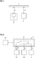
- FIG. 5 shows a switching unit S with drive components SE1, SE2, AS.
- the switching unit S is connected to the first control device SE1, to the second control device SE2 and to the converter U by a respective network connection N, N1, N2.
- the first control device SE1 is also connected to the switching unit S with a signal connection SV.
- the signal connection is integrated into the respective network connection N.
- the switching unit S has an application switch AP, wherein the application switch AP is designed to disconnect or connect the network connections N1, N2 between the drive components SE1, SE2, U. By the application switch AP a variety of different connections of each connected drive components (SE1, SE2, U) can be realized.
- the data flow through the respective network connection N, N1, N2 is bidirectional, as indicated by the double arrows. This also applies to the embodiments shown in the further FIG.
- the switching unit S may be connected to a human-machine interface HMI.
- the man-machine interface HMI is preferably used as an input option of the respective connection / disconnection of the respective network connection N, N1, N2 of the respective drive components SE1, SE2, U with each other.
- connection switch AS is merely exemplary. Therefore, the compounds are shown in dashed lines.
- the human-machine interface HMI is also only optional and therefore shown in dashed lines.
- the invention relates to a method for the separation and / or connection of drive components SE1, SE2, U, AS, ET and a drive device.
- a network connection N1, N2, N is used to connect the drive components SE1, SE2, AS, U, ET.
- An application switch AP is used to connect or disconnect a network connection N1, N2, N.
- the application switch AP is connected to one of the drive components SE1, SE2, AS, U, ET controllable.
- the signal for disconnecting or connecting the network connection N1, N2, N between in each case two drive components SE1, SE2, AS, U, ET is preferably provided by a signal connection SV or the network connection N1, N2, N to the application switch AP.
- network connections N1, N2, N no longer have to be manually connected or disconnected.
Landscapes
- Engineering & Computer Science (AREA)
- Computer Networks & Wireless Communication (AREA)
- Signal Processing (AREA)
- Small-Scale Networks (AREA)
Priority Applications (1)
| Application Number | Priority Date | Filing Date | Title |
|---|---|---|---|
| EP16191824.8A EP3301858A1 (fr) | 2016-09-30 | 2016-09-30 | Procédé et dispositif de propulsion |
Applications Claiming Priority (1)
| Application Number | Priority Date | Filing Date | Title |
|---|---|---|---|
| EP16191824.8A EP3301858A1 (fr) | 2016-09-30 | 2016-09-30 | Procédé et dispositif de propulsion |
Publications (1)
| Publication Number | Publication Date |
|---|---|
| EP3301858A1 true EP3301858A1 (fr) | 2018-04-04 |
Family
ID=57103838
Family Applications (1)
| Application Number | Title | Priority Date | Filing Date |
|---|---|---|---|
| EP16191824.8A Withdrawn EP3301858A1 (fr) | 2016-09-30 | 2016-09-30 | Procédé et dispositif de propulsion |
Country Status (1)
| Country | Link |
|---|---|
| EP (1) | EP3301858A1 (fr) |
Citations (3)
| Publication number | Priority date | Publication date | Assignee | Title |
|---|---|---|---|---|
| WO2001024013A2 (fr) * | 1999-09-30 | 2001-04-05 | Infineon Technologies Ag | Circuit de protection d'un reseau systeme a bus d'acces aleatoire |
| DE102007009042A1 (de) * | 2006-02-28 | 2007-08-30 | Denso Corp., Kariya | Buskommunikationssystem |
| DE102010026768A1 (de) * | 2010-07-10 | 2011-04-21 | Daimler Ag | Kraftfahrzeugsicherheitssystem für eine elektrische Kraftfahrzeugantriebsvorrichtung |
-
2016
- 2016-09-30 EP EP16191824.8A patent/EP3301858A1/fr not_active Withdrawn
Patent Citations (3)
| Publication number | Priority date | Publication date | Assignee | Title |
|---|---|---|---|---|
| WO2001024013A2 (fr) * | 1999-09-30 | 2001-04-05 | Infineon Technologies Ag | Circuit de protection d'un reseau systeme a bus d'acces aleatoire |
| DE102007009042A1 (de) * | 2006-02-28 | 2007-08-30 | Denso Corp., Kariya | Buskommunikationssystem |
| DE102010026768A1 (de) * | 2010-07-10 | 2011-04-21 | Daimler Ag | Kraftfahrzeugsicherheitssystem für eine elektrische Kraftfahrzeugantriebsvorrichtung |
Similar Documents
| Publication | Publication Date | Title |
|---|---|---|
| EP3353610B2 (fr) | Unité de liaison, système de surveillance et procédé permettant de faire fonctionner un système d'automatisation | |
| EP2182418B1 (fr) | Procédé et dispositif d'accès à un module de fonctionnement d'un système d'automatisation | |
| EP1279076A2 (fr) | Procede de commande et installation de production industrielle equipee d'un systeme de commande par le web | |
| EP0917034B1 (fr) | Procédé de surveillance et/ou d'entretien à distance pour machine de moulage à injection | |
| EP4097927B1 (fr) | Adaptateur d'appareil basé sur spe pour connecter un appareil de terrain compatible non ethernet à un système de commande de processus basé sur ethernet | |
| DE10304903A1 (de) | Vorrichtung zur Automatisierung und/oder Steuerung von Werkzeug- oder Produktionsmaschinen | |
| EP2729852A1 (fr) | Procédé de configuration d'un module d'interface de communication dans un système de commande ou d'automatisation | |
| WO2018036708A1 (fr) | Passerelle et procédé de connexion d'un système de source de données à un système informatique | |
| DE202010016362U1 (de) | Anordnung mit einer übergeordneten Steuereinheit und zumindest einem mit der Steuereinheit verbindbaren intelligenten Feldgerät | |
| DE102004051106A1 (de) | Kunststoffverarbeitende Maschine | |
| WO2018215289A1 (fr) | Unité de module permettant de connecter un abonné de bus de données | |
| EP2997427B1 (fr) | Système de commande et procédé de commutation de modules d'entrée/sortie d'un système de commande | |
| DE102016000126A1 (de) | Serielles Bussystem mit Koppelmodulen | |
| EP3528064B1 (fr) | Système de commande et procédé associé de mise en marche, de commande et de surveillance pour des éléments d'alimentation électrique | |
| DE102007054662A1 (de) | Feldgerät | |
| EP3420426B1 (fr) | Dispositif et procede d'adaptation d'une commande numerique sur une machine a commander | |
| EP3125053B1 (fr) | Procede et composant peripherique destines a la transmission de variables hart et unite centrale destinee a lire les variables hart | |
| EP0792078B1 (fr) | Système d'interface pour capteurs-actionneurs | |
| EP3282331B1 (fr) | Unité d'entrée/sortie pour la connection de dispositifs de terrain | |
| EP3301858A1 (fr) | Procédé et dispositif de propulsion | |
| EP2730063A1 (fr) | Module d'interface de communication pour système d'automatisation | |
| EP3331201B1 (fr) | Réseau modbus destiné à une connexion distante redondante | |
| DE102009014620B4 (de) | Adressabhängige Sicherheitscodefolgen für sichere Eingangsslaves bei AS-Interface | |
| EP3244274B1 (fr) | Appareil électrique doté d'une unite fonctionnelle | |
| EP2618522A1 (fr) | Procédé de conception assistée par ordinateur d'une installation d'automatisation |
Legal Events
| Date | Code | Title | Description |
|---|---|---|---|
| PUAI | Public reference made under article 153(3) epc to a published international application that has entered the european phase |
Free format text: ORIGINAL CODE: 0009012 |
|
| AK | Designated contracting states |
Kind code of ref document: A1 Designated state(s): AL AT BE BG CH CY CZ DE DK EE ES FI FR GB GR HR HU IE IS IT LI LT LU LV MC MK MT NL NO PL PT RO RS SE SI SK SM TR |
|
| AX | Request for extension of the european patent |
Extension state: BA ME |
|
| STAA | Information on the status of an ep patent application or granted ep patent |
Free format text: STATUS: THE APPLICATION IS DEEMED TO BE WITHDRAWN |
|
| 18D | Application deemed to be withdrawn |
Effective date: 20181005 |