EP3301975B1 - Appareils et procédés de mesure de cellules voisines inter-rat ou d'interfréquence - Google Patents
Appareils et procédés de mesure de cellules voisines inter-rat ou d'interfréquence Download PDFInfo
- Publication number
- EP3301975B1 EP3301975B1 EP16191012.0A EP16191012A EP3301975B1 EP 3301975 B1 EP3301975 B1 EP 3301975B1 EP 16191012 A EP16191012 A EP 16191012A EP 3301975 B1 EP3301975 B1 EP 3301975B1
- Authority
- EP
- European Patent Office
- Prior art keywords
- inter
- transmitter
- receiver
- feedback receiver
- user equipment
- Prior art date
- Legal status (The legal status is an assumption and is not a legal conclusion. Google has not performed a legal analysis and makes no representation as to the accuracy of the status listed.)
- Not-in-force
Links
Images


Classifications
-
- H—ELECTRICITY
- H03—ELECTRONIC CIRCUITRY
- H03F—AMPLIFIERS
- H03F1/00—Details of amplifiers with only discharge tubes, only semiconductor devices or only unspecified devices as amplifying elements
- H03F1/32—Modifications of amplifiers to reduce non-linear distortion
- H03F1/3241—Modifications of amplifiers to reduce non-linear distortion using predistortion circuits
- H03F1/3247—Modifications of amplifiers to reduce non-linear distortion using predistortion circuits using feedback acting on predistortion circuits
-
- H—ELECTRICITY
- H03—ELECTRONIC CIRCUITRY
- H03F—AMPLIFIERS
- H03F3/00—Amplifiers with only discharge tubes or only semiconductor devices as amplifying elements
- H03F3/20—Power amplifiers, e.g. Class B amplifiers, Class C amplifiers
- H03F3/24—Power amplifiers, e.g. Class B amplifiers, Class C amplifiers of transmitter output stages
-
- H—ELECTRICITY
- H04—ELECTRIC COMMUNICATION TECHNIQUE
- H04B—TRANSMISSION
- H04B1/00—Details of transmission systems, not covered by a single one of groups H04B3/00 - H04B13/00; Details of transmission systems not characterised by the medium used for transmission
- H04B1/38—Transceivers, i.e. devices in which transmitter and receiver form a structural unit and in which at least one part is used for functions of transmitting and receiving
- H04B1/3805—Transceivers, i.e. devices in which transmitter and receiver form a structural unit and in which at least one part is used for functions of transmitting and receiving with built-in auxiliary receivers
-
- H—ELECTRICITY
- H04—ELECTRIC COMMUNICATION TECHNIQUE
- H04B—TRANSMISSION
- H04B17/00—Monitoring; Testing
- H04B17/10—Monitoring; Testing of transmitters
- H04B17/11—Monitoring; Testing of transmitters for calibration
- H04B17/13—Monitoring; Testing of transmitters for calibration of power amplifiers, e.g. gain or non-linearity
-
- H—ELECTRICITY
- H04—ELECTRIC COMMUNICATION TECHNIQUE
- H04L—TRANSMISSION OF DIGITAL INFORMATION, e.g. TELEGRAPHIC COMMUNICATION
- H04L25/00—Baseband systems
- H04L25/02—Details ; arrangements for supplying electrical power along data transmission lines
- H04L25/06—DC level restoring means; Bias distortion correction ; Decision circuits providing symbol by symbol detection
- H04L25/061—DC level restoring means; Bias distortion correction ; Decision circuits providing symbol by symbol detection providing hard decisions only; arrangements for tracking or suppressing unwanted low frequency components, e.g. removal of DC offset
- H04L25/063—Setting decision thresholds using feedback techniques only
-
- H—ELECTRICITY
- H04—ELECTRIC COMMUNICATION TECHNIQUE
- H04W—WIRELESS COMMUNICATION NETWORKS
- H04W36/00—Hand-off or reselection arrangements
- H04W36/24—Reselection being triggered by specific parameters
- H04W36/30—Reselection being triggered by specific parameters by measured or perceived connection quality data
Definitions
- RAT Radio Access Technology
- Handover performance depends on neighboring cell search and measurement update rate.
- UE User Equipment
- 3GPP 3 rd Generation Partnership Project
- a high measurement update rate does not come for free.
- inter-frequency (inter-freq) handover at a fixed point of time, the number of frequency carriers that can be measured in parallel is dominated by the UE's number of Radio Frequency (RF) receiver chains which are available for inter-frequency or inter-RAT measurements.
- RF Radio Frequency
- LTE Long-Term Evolution
- a measurement gap interrupts downlink signal demodulation of the serving cell frequency carrier and switches a Radio Frequency (RF) receiver port to a different frequency carrier to apply search and measurement there.
- the RF receiver port switches back to the serving cell frequency.
- the serving cell data demodulation has to be interrupted regularly for a certain duration, thereby sacrificing DL throughput performance because of the interruption of the serving cell demodulation chain.
- US 2003/0186698 A1 suggests addressing the reduced DL throughput performance by reusing one of the MIMO receivers of a multi-transceiver-MIMO-UE.
- a user equipment for a wireless or cellular communication system.
- the user equipment comprises a transmitter configured to generate a transmit signal, a transmitter feedback receiver coupled to the transmitter and configured to measure a power of the transmit signal in a first mode of operation, and control circuitry configured to select a second mode of operation of the transmitter feedback receiver, in which the transmitter feedback receiver is configured to measure one or more neighboring inter-frequency or inter-RAT cells or base stations.
- a method for measuring one or more neighboring inter-frequency or inter-RAT cells or base stations with a user equipment of a wireless or cellular communication system the user equipment comprising a transmitter configured to generate a transmit signal.
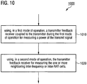
- the method includes using, in a first mode of operation, a transmitter feedback receiver coupled to the transmitter during the first mode of operation for measuring a power of the transmit signal, and using, in a second mode of operation, the transmitter feedback receiver for measuring the one or more neighboring inter-frequency or inter-RAT cells or base stations.
- a cell need not necessarily be part of a cellular communication system, but can more generally be understood as an area served by a base station or access point of a wireless communication system to provide radio coverage in that area.
- the term "cell” can refer to sectors of a cell, to macrocells, microcells, picocells, femtocells, or the like. Typically a cell has associated therewith a unique cell identifier (cell ID).
- cell ID unique cell identifier
- macrocells provide coverage larger than small cells including microcells, picocells, and femtocells.
- Small cells are low-powered radio access nodes that can operate in licensed and unlicensed spectrum that have a range of 10 meters to 1 or 2 kilometers. They are "small" compared to a mobile macrocell, which may have a range of a few tens of kilometers.
- the antennas for macrocells can be mounted on ground-based masts, rooftops and other existing structures, at a height that provides a clear view over the surrounding buildings and terrain.
- a cell may also be a WiFi hotspot, for example.
- an intra-frequency (intra-freq) measurement occurs when a current serving and a potential target cell operate on the same carrier frequency.
- a UE may be able to carry out such measurements without measurement gaps. This is because the RF receiver of the UE may be able to measure reference signals of the target cell while simultaneously performing data communication in the serving cell on the same carrier frequency.
- inter-frequency (inter-freq) measurement occurs when the potential target cell operates on a different carrier frequency as compared to the current serving cell.
- the carrier frequency of the current serving cell may be f 0
- the carrier frequency of the potential target cell may be f 1 .
- inter-RAT (Radio Access Technology) measurement occurs when the target cell operates on a different RAT as compared to the current cell.
- the RAT of the current serving cell may be LTE
- the RAT of the potential target cell may be UMTS (Universal Mobile Telecommunication System) or WiFi (Wireless Fidelity).
- FIG. 1 illustrates an example of an inter-freq measurement scenario 100.
- inter-frequency carriers f1, f2, and f3 are monitored.
- a UE is served in a current cell on carrier frequency f0, while different target cells operate on different carrier frequencies f1, f2 and f3.
- a UE having only one RF receiver is typically not able to carry out target cell measurements without subsequent measurement gaps 110. This is because the RF receiver of UE needs to switch to a different carrier frequency to perform respective measurements and then switch back to f0 to perform data communication.
- measurement gaps 110 are typically needed by the UE (having a single RF receiver chain) to monitor cells on other frequencies than the serving cell, i.e. inter-frequency as well as inter-RAT (e.g.
- Measurement gaps 110 are periods where UE switches off its receiver and transmitter from the serving cell and starts listening to neighboring cells.
- Each measurement gap 110-1, 110-2, and 110-3 interrupts the downlink signals demodulation in the serving cell frequency carrier f0, and switches the RF receiver port to a different frequency carrier to apply search and measurement there. After inter-freq measurement is done, the RF receiver port switches back to the serving cell frequency f0.
- the serving cell data demodulation has to be interrupted every 40ms (or every 80ms depending on eNodeB configurations) for a 6ms duration.
- base stations may also be referred to as NodeB or eNodeB according to 3GPP terminology.
- the DL throughput performance is sacrificed because of the interruption of the serving cell demodulation chain.
- the shortcomings of FIG. 1 are that the intra-freq serving cell reception and demodulation is interrupted periodically (for example, 6ms out of every 40ms or 80ms), which gives non-optimal throughput (for example, 15% throughput loss comparing with non-interruption case).
- the UE can apply measurement only in one inter-freq carrier at a time. When the number of monitored frequency carriers is increased, the search and measurement rate is going down accordingly which degrades the handover performance.
- Carrier Aggregation can be used in order to increase the bandwidth, and thereby increase the bitrate.
- Each aggregated carrier is referred to as a Component Carrier (CC).
- CC Component Carrier
- a component carrier can have a bandwidth of 1.4, 3, 5, 10, 15 or 20 MHz and a maximum of five component carriers may be aggregated, hence the maximum aggregated bandwidth may be 100 MHz.
- FDD Frequency Division Duplex
- the number of aggregated carriers can be different in downlink (DL) and uplink (UL).
- the UE could then measure a different inter-freq carrier in parallel so that the UE does not need to switch off the RF receiver port which is used for the serving cell throughput.
- CA as, for example, low-cost devices
- this concept does not work.
- the UE works in full CA mode this concept does not work because all RF receiver chains would already be busy for CA.
- the supported inter-freq carriers are restricted by band limitations. A RF receiver port for an aggregated carrier usually only supports a portion of frequency bands (while the other port will support the remaining). So there can be inter-frequency carriers which cannot be supported by the second RF receiver port.
- another solution would be just to add an additional dedicated independent RF receiver chain just for inter-freq measurements. However, the hardware cost for this would be prohibitive.
- the present disclosure proposes to perform inter-freq and/or inter-RAT measurements using a UE's transmitter FeedBack Receiver (TX FBR).
- TX FBR is an existing component in multiple existing RF transceivers and commonly serves purposes like closed-loop transmission power control and TX or calibration.
- a TX FBR usually receives a fed back version of a transmit signal from the transmitter portion of the transceiver.
- the TX FBR is coupled to the transmitter for feedback- unlike a main receiver of the UE.
- a TX FBR can comprise a full RF receiver chain starting from getting analog RF signals until generating final digitalized Inphase and Quadrature (IQ) data streams.
- UL uplink
- the present disclosure proposes to use the TX FBR for downlink reception at this moment.
- FIG. 2 illustrates a schematic block diagram of a UE 200 employing the proposed concept.
- UE 200 comprises transmit circuitry 210 which is configured to generate an RF transmit signal 220 which can be radiated via one or more antennas 260.
- UE 200 also comprises a transmitter feedback receiver (TX FBR) 230 which is coupled to transmit circuitry 210 or a signal path thereof in order to feed back transmit signal 220 and to measure parameters, such as a power, for example, of transmit signal 220 in a first mode of operation of TX FBR 230.
- TX FBR 230 receives a fed back version of transmit signal 220 during the first mode of operation.
- UE 200 also comprises control circuitry 240 which is configured to select a second mode of operation of TX FBR 230, in which TX FBR 230 is configured to measure one or more neighboring inter-frequency or inter-RAT cells and thus performs spectrum sensing.
- control circuitry 240 which is configured to select a second mode of operation of TX FBR 230, in which TX FBR 230 is configured to measure one or more neighboring inter-frequency or inter-RAT cells and thus performs spectrum sensing.
- the TX FBR 230 can receive and evaluate signals, such as synchronization signals, from neighboring cells during the second mode of operation.
- UE 200 typically also comprises main receiver circuitry 250 for receiving and demodulating a serving cell signal at one or more serving cell carrier frequencies, depending on whether carrier aggregation is used or not.
- main receiver circuitry 250 can comprise more than one parallel RF receiver chain, if UE 200 is capable of carrier aggregation.
- Main receiver circuitry 250 can be coupled to the one or more antennas 260 which are also used for transmitting transmit signal 220 or can be coupled to one ore more dedicated RX antennas 270, depending on the design of UE 200.
- main receiver circuitry 250 does not receive and evaluate a fed back version of transmit signal 220 from the UE's transmitter portion 210. Instead it is configured to receive and evaluate downlink signals from base stations.
- TX FBR 230 of UE 200 can be used for inter-frequency or inter-RAT measurements instead of as well as in addition to main receiver circuitry 250 of UE 200, thus enabling enhancements of inter-freq and/or inter-RAT measurement of mobile terminals used in mobile communication systems.
- the proposed functionality of UE 200 may be purely achieved with amendments of a conventional UE's firmware in some examples. Also, there may be hardware modifications with respect to conventional UEs not having the proposed features.
- UE 200 can be used to carry out a method in accordance with the present disclosure.
- An example of such a method 1000 for measuring one or more neighboring inter-frequency or inter-RAT cells with a UE of a cellular communication system is shown in FIG. 10 .
- Method 1000 includes using 1010, in a first mode of operation (e.g., uplink transmission), the UE's transmitter feedback receiver coupled to the UE's transmitter during the first mode of operation for measuring a power of the transmit signal.
- a second mode of operation e.g. neighbor cell spectrum sensing
- the transmitter feedback receiver is used 1020 for measuring the one or more neighboring inter-frequency or inter-RAT cells.
- examples of the present disclosure are applicable to any kind of wireless system such as for example 3GPP (Third Generation Partnership Project) specifications, notably Long Term Evolution (LTE) and Long Term Evolution-Advanced (LTE-A) and LTE-Advanced Pro. It is understood that such exemplary scenarios are demonstrative in nature, and accordingly may be similarly applied to other mobile communication technologies and standards, such as any Cellular Wide Area radio communication technology, which may include e.g.
- 5G 5th Generation
- GSM Global System for Mobile Communications
- GPRS General Packet Radio Service
- EDGE Enhanced Data Rates for GSM Evolution
- 3GPP Third Generation Partnership Project
- UMTS Universal Mobile Telecommunications System
- FOMA Freedom of Multimedia Access
- 3GPP LTE Long Term Evolution
- 3GPP LTE Advanced Long Term Evolution Advanced
- 3GPP LTE-Advanced Pro CDMA2000 (Code division multiple access 2000), CDPD (Cellular Digital Packet Data), Mobitex, 3G (Third Generation), CSD (Circuit Switched Data), HSCSD (High-Speed Circuit-Switched Data), UMTS (3G) (Universal Mobile Telecommunications System (Third Generation)), W-CDMA (UMTS) (Wideband Code Division Multiple Access (Universal Mobile Telecommunications System)), HSPA (High Speed Packet Access), HSDPA (High-Speed Downlink Packet Access), HSUPA (High-Speed Uplink Packet Access), HSPA+ (High Speed Packet Access Plus), UMTS-TDD (Universal Mobile Telecommunications System - Time-Division Duplex), TD-CDMA (Time Division - Code Division Multiple Access
- 3rd Generation Partnership Project Release 8 (Pre-4G) (3rd Generation Partnership Project Release 8 (Pre-4th Generation)), 3GPP Rel. 9 (3rd Generation Partnership Project Release 9), 3GPP Rel. 10 (3rd Generation Partnership Project Release 10), 3GPP Rel. 11 (3rd Generation Partnership Project Release 11), 3GPP Rel. 12 (3rd Generation Partnership Project Release 12), 3GPP Rel. 13 (3rd Generation Partnership Project Release 14), 3GPP Rel. 14 (3rd Generation Partnership Project Release 14), 3GPP Rel. 15 (3rd Generation Partnership Project Release 15), 3GPP Rel. 16 (3rd Generation Partnership Project Release 16), 3GPP Rel.
- UE or mobile terminal 200 can be any device used by an end-user to communicate. It can be a hand-held telephone, such as a smartphone, a laptop computer equipped with a mobile broadband adapter, or any other device. It can connect to base stations or NodeB/eNodeB's and/or to WiFi access points.
- FIG. 3A To provide a better understanding of the proposed concept, an example of a conventional transmitter feedback receiver will be described with reference to FIG. 3A before illustrating a modified transmitter feedback receiver according to an example of the present disclosure in FIG. 3B .
- FIG. 3A shows a block diagram of a transceiver circuit 300, which can be used in a UE.
- Transceiver circuit 300 comprises a transmit (TX) portion 310 which is configured to generate an RF transmit signal 320.
- TX portion 310 can include digital as well as analog circuit components.
- baseband signal processing can be performed in the digital domain by using digital hardware components such as Digital Signal Processors (DSPs), Field Programmable Gate Arrays (FPGAs), Application Specific Integrated Circuits (ASICs) or the like.
- DSPs Digital Signal Processors
- FPGAs Field Programmable Gate Arrays
- ASICs Application Specific Integrated Circuits
- a digital baseband signal can be transformed into the analog domain by using one or more Digital-to-Analog Converters (DACs).
- DACs Digital-to-Analog Converters
- the phase PM(t) of an RF signal at frequency f c which is generated by a controllable local oscillator 325, can be directly modulated.
- the resulting RF TX signal 320 can be amplified by Power Amplifier (PA) 326 and filtered by a bandpass filter 327 before being radiated via antenna 360.
- PA Power Amplifier
- the transmit path also includes a directional coupler 328 which is configured to couple a defined amount of the electromagnetic TX power in the TX path to a port enabling the RF TX signal to be fed back to transmitter feedback receiver 330.
- transmitter feedback receiver 330 is coupled to TX portion 310 via coupler 328.
- a first attenuator (ATT) 329 can be used to decrease the power of the fed back RF TX signal.
- the example transmitter feedback receiver 330 comprises an analog direct demodulator and a digital frontend 337 for data post-processing.
- the analog demodulation path includes a switch 331 for selecting or bypassing the first attenuator (ATT) 329.
- the selected signal is fed to a second attenuator (ATT) 332 for input power levelling followed by a Low-Noise Amplifier (LNA) 333.
- a mixer 334 for down-converting the output signal of LNA 334 is driven by local oscillator 325 tuned to the channel frequency fc and typically containing the modulated phase signal PM(t) on top.
- transmitter feedback receiver 330 uses RF TX signal 320 for down-converting the fed back RF TX signal.
- transmitter feedback receiver 330 and transmitter 310 share the same LO 325.
- a Trans Impedance Amplifier (TIAMP) 335 can be used for fine-tuning the input signal amplitude of the down-converted signal to provide a full-scale baseband signal to Analog-to-Digital Converter (ADC) 336.
- TIAMP Trans Impedance Amplifier
- transmitter feedback receiver 330 is operated together with TX portion 310 and used mainly for power measurements in TX transmission mode (first mode).
- the transmitter feedback receiver gain can be fixed for each Frequency Band and RAT (Radio Access Technology). With that a dynamic range of about 30dB can be achieved maintaining a Signal-to-Noise Ratio (SNR) of 26dB.
- SNR Signal-to-Noise Ratio
- the TX architecture comprises a polar transmitter, i.e. the Local Oscillator is containing the phase modulation of the transmit signal PM(t) which distorts the signal demodulation in the transmitter feedback receiver.
- the illustrated architecture a full signal demodulation might not be possible with the illustrated architecture.
- the amplitude of the down-converted signal would be undistorted, but the phase of the down-converted signal would be distorted.
- TX 310 or certain portions thereof may be deactivated when the transmitter feedback receiver is to be used for spectrum sensing during its second mode of operation.
- control circuitry 240 see Fig.
- the LO 325 may subsequently be tuned to different carrier frequencies (e.g., f1, f2, f3, see Fig. 1 ) of potential neighboring target cells during the second mode of operation.
- the example transceiver 350 shown in FIG. 3B differs from transceiver 300 of FIG. 3A in several aspects.
- it comprises a switch 351 between coupler 328 and antenna 360.
- switch 351 allows the TX signal 320 to propagate from coupler 328 to antenna 360.
- second mode of operation (spectrum sensing) switch 351 decouples coupler 328 and upstream TX portions from antenna 360 and allows RX signals to propagate from antenna 360 to modified transmitter feedback receiver 330'.
- Further switches 352, 353 can be used to bypass coupler 328 and/or attenuator 329 to increase the gain at least by the coupling factor (for example, 20dB).
- control circuitry 240 can comprise one or more switches 351, 352, 353 configured to couple transmitter feedback receiver 330' to the transmit path of the transmit circuitry 310 during the first mode of operation and to connect the transmitter feedback receiver 330' to at least one (RX) antenna 360 during the second mode of operation.
- switches 351, 352, 353 configured to couple transmitter feedback receiver 330' to the transmit path of the transmit circuitry 310 during the first mode of operation and to connect the transmitter feedback receiver 330' to at least one (RX) antenna 360 during the second mode of operation.
- Switches 354-1 and 354-2 can be used to select, during the second mode of operation, a second LNA 333-2 with improved noise figure and gain (for example, adding 10 dB) with respect to first LNA 333-1 used during the first mode of operation, compromising a slightly higher current consumption.
- bypass switch 354-1 could also be placed after attenuator 332 in other implementations.
- modified transmitter feedback receiver 330' comprises a first LNA 333-1 with a first noise figure and a first gain for use during the first mode of operation and a second LNA 333-2 with a second noise figure lower than the first noise figure and with a second gain higher than the first gain for use during the second mode of operation.
- the sensitivity of the transmitter feedback receiver 330' can be increased for spectrum sensing during the second mode of operation.
- the usage of different LNAs for the different modes of operation is optional. In some examples, only one LNA for both modes may be used. Thereby the RX sensitivity of the transmitter feedback receiver can be the same for both modes or can be varied by other means, such as applying different levels of signal attenuation in the first and second mode, respectively.
- attenuator 332 may also be a variably adjustable attenuator in some implementations, for example.
- the input of ADC 336 is getting an additional gain stage 355 yielding additional 20dB, for example.
- the additional gain stage 355 may be part of the existing TIAMP 335, a bypass of TIAMP 335, or a separate gain stage in the chain before or after TIAMP 335.
- the example architecture of Fig. 3B is capable of levelling a wide range of antenna power. After the enhancement of bypassing coupler 328 using switch 352, additional amplifier 355 and new LNA 333-2, even RX sensitivity requirements for LTE inter-freq measurement can be fulfilled.
- the TX can be deactivated during RX channel search (second mode of operation). Therefore the transmitter feedback receiver can be operated with an LO tuned to constant frequency (no phase modulation).
- the demodulated signal after the transmitter feedback receiver can be sampled in the FBR digital block 337 and further post-processed in a baseband processor (not shown).
- the impact of the modifications on baseband may mainly be covered by firmware changes. Hardware changes to baseband processing are not necessary.
- CSC Cell Search Component
- baseband architecture CSC may be running independently from a throughput demodulation chain. Because of that, in order to support the proposed concept, CSC does not have to be interrupted and can act almost transparent when IQ samples are actually coming from the TX feedback receiver and not the main RX receiver.
- the IQ samples may be coming only from one physical antenna since TX may only use one antenna. But from the baseband point of view, it may behave the same as single RX mode which is already supported by current products. Therefore, functional wise, to support the proposed concept, it does not need hardware change.
- FIG. 4 illustrates a flowchart of a first sub-method 400 relating to dynamic RF receiver port switching based on signal quality awareness.
- Method 400 includes waiting 402 until a measurement gap interval is reached.
- an RX selection decision flag is read, wherein the RX selection decision flag indicates whether to select the transmitter feedback receiver or the main receiver of a UE for neighboring cell measurement.
- inter-freq measurement with signal quality metric e.g. Signal-to-Interference-plus-Noise Ratio, SINR
- SINR Signal-to-Interference-plus-Noise Ratio
- a UE may be configured to measure a measurement signal quality when measuring one or more neighboring cells, and, if the measurement signal quality exceeds a predefined threshold, to select the transmitter feedback receiver for measuring the one or more neighboring cells, otherwise to select a main receiver for measuring the one or more neighboring cells.
- method 400 proposes to run-time measure the signal quality when applying neighboring measurement and track the signal quality in the field. Based on the tracked signal quality, in case the tracked signal quality metric (for example SINR) is below a predefined threshold, the UE can fall back to legacy scheme (using main RF receiver port with measurement gap interruption) in the next measurement gap. In case the signal quality metric is higher than a pre-defined threshold, the TX feedback receiver is re-activated again.
- the tracked signal quality metric for example SINR
- the UE can fall back to legacy scheme (using main RF receiver port with measurement gap interruption) in the next measurement gap.
- the signal quality metric is higher than a pre-defined threshold, the TX feedback receiver is re-activated again.
- FIG. 5 illustrates an example of a second sub-method 500 relating to alternating physical antenna connection per measurement gap and pipeline combining.
- control circuitry 240 may be configured to couple the UE's transmitter feedback receiver to a first RX antenna during a first measurement interval of the second mode of operation and to couple the transmitter feedback receiver to a second RX antenna during a second measurement interval of the second mode of operation and to combine measurements of the first and the second measurement interval. Thereby a Signal-to-Noise Ratio (SNR) of the measured signals may be increased.
- SNR Signal-to-Noise Ratio
- Method 500 proposes a UE to alternate the connection of different the physical antennas with the transmitter feedback receiver in different measurement gaps, apply inter-freq neighboring cell search and measurement on the respective connected physical antenna, and combine the results with the previous gap where the other physical antenna was connected.
- cell search component non-coherent combining for cell detection + maximal antenna selection for Reference Signal Received Power, RSRP, measurement
- RSRP Reference Signal Received Power
- measurement for LTE cell search and measurement
- the performance loss in worst case is 2dB, but still within the margin to satisfied 3GPP requirement.
- the measurement update rate is not halved but kept the same because of the pipelined antenna combining.
- FIG. 6 it is illustrated an example scheduling diagram where inter-freq measurements are performed using the transmitter feedback receiver on top of (i.e., in addition) to conventional measurement gap handling by a main receiver.
- a first neighbor cell operating at carrier frequency f1 is measured using the main receiver, while a second neighbor cell operating at carrier frequency f2 is measured using the transmitter feedback receiver.
- a third neighbor cell operating at carrier frequency f3 is measured using the main receiver, while a fourth neighbor cell operating at carrier frequency f4 is measured using the transmitter feedback receiver.
- a fifth neighbor cell operating at carrier frequency f5 is measured using the main receiver, while a sixth neighbor cell operating at carrier frequency f6 is measured using the transmitter feedback receiver.
- the first neighbor cell operating at carrier frequency f1 is measured again using the main receiver, while the second neighbor cell operating at carrier frequency f2 is measured again using the transmitter feedback receiver, and so on.
- the main receiver and the transmitter feedback receiver of a UE may be configured to simultaneously measure different neighboring cells during dedicated measurement periods (measurement gaps). This can improve the measurement update rate, so that better LTE handover performance can be achieved.
- the main receiver could also continue demodulating a serving cell signal, while the transmitter feedback receiver measures one or more neighbor cells during measurement gaps.
- the main receiver could also be configured to receive the serving cell signal and the transmitter feedback receiver could be configured to simultaneously measure one or more neighboring cells.
- FIG. 7 Another example relating to Time Division Duplex (TDD) scenarios is shown in FIG. 7 .
- neighbor cell measurements 710 are done with the transmitter feedback receiver during downlink sub-frames 720 which are demodulated with a UE's main receiver.
- a UE can indicate the eNodeB to disable the measurement gap assignments. For example, this can be done by setting interFreqNeedForGaps in UE-EUTRA-Capability structure to be false.
- a UE can perform inter-freq measurement using its transmitter feedback receiver during TDD downlink sub-frames or special sub-frames. Note that at TDD downlink or special sub-frames, uplink TX can be disabled so the TX feedback receiver is free for use.
- a UE may be configured for TDD operation and its transmitter feedback receiver may be configured to measure one or more neighboring cells during TDD downlink frames. This will not only improve the LTE inter-freq measurement update rate for better handover performance, but also significantly improve the throughput performance. That is because the downlink data reception and uplink data transmission are not interrupted by inter-freq measurement gaps.
- TDD ULDL config index to be 5.
- 6/8*4 18% throughput increase, while at the same time the inter-freq handover performance is also kept.
- FIG. 8 A further possible scheme relating to discontinuous transmission (DTX) is shown in FIG. 8 .
- neighbor cell measurements 810 are performed with the transmitter feedback receiver during periods 820 of TX inactivity.
- HSPA High Speed Packet Access
- DTX discontinuous transmission
- the UE can apply the proposed scheme to do LTE measurements by TX feedback receiver.
- a UE can be configured for DTX and its transmitter feedback receiver can be configured to measure one or more neighboring cells during periods of data transmission inactivity. This can improve the inter-RAT performance because besides of the existing 3G measurement gaps which are assigned to LTE.
- LTE then has more time opportunities to apply neighboring cell search and measurement in non-3G-gap locations, and therefore can achieve higher measurement update rate and therefore better handover performance. Please note that it can also help removing LTE i-RAT gap allocations for HSPA.
- FDD LTE measurement gaps can be exploited in order to identify the availability of shared TDD bands for 3GPP Licensed-Assisted Access (LAA) usage.
- LAA refers to the use of the 4G LTE radio communications technology in unlicensed spectrum, such as the 5 GHz band used by dual-band WiFi equipment.
- shared bands When shared bands are available, they can be combined through FDD/TDD carrier aggregation.
- Measurement gaps may be introduced in the shared band emissions that coincide with the gaps in the dedicated licensed bands. Then, a UE's TX feedback receiver can be exploited during those gaps to identify whether a priority system is coming back and the band needs to be vacated. In case that it cannot be ensured that the gaps in the dedicated licensed band and the shared band perfectly coincide, then either
- FIG. 9 An example of the proposed method 900 is shown in FIG. 9 .
- CA Carrier Aggregation
- PCell Primary serving Cell
- Scell1 Secondary serving Cell
- RRC Radio Resource Control
- PCC Primary Component Carrier
- SCC Secondary Component Carriers
- the SCCs can be added and removed as required, while the PCC is only changed at handover.
- both main RF receiver ports of UE are busy with downlink reception and demodulation from PCell and Scell1. Even in measurement gaps 910, both RF receiver ports are fully occupied for dual inter-freq layer measurement in parallel at frequencies f1 and f2.
- TX feedback receiver port can be used for receiving RF samples from the unlicensed band 906 at frequency f3 for spectrum sensing.
- TX feedback receiver can be configured to measure one or more neighboring inter-frequency or inter-RAT cells in unlicensed frequency spectrum. This can be done during each measurement gap slot 910 where TX is anyhow idle.
- UE can de-activate Scell1 (lower bandwidth) in the licensed band and can add a new Scell2 (higher bandwidth) as Secondary serving cell in the unlicensed band at f3 and can operate in TDD/FDD joint CA mode. Later on (after measurement gap 910-4 in the illustrated example), UE can switch back to Scell1 if TX feedback receiver detects that there are incumbents in the unlicensed band 906 again.
- the present disclosure proposes to apply inter-freq measurement using a UE's TX FeedBack Receiver (FBR), which is an existing component in multiple existing RF transceivers. It usually serves the main purposes for closed-loop transmission power control and TX calibration. It contains already a full RF receiver chain starting from getting analog RF signals until generating final digitalized IQ streams. This is feasible because during inter-freq measurement gaps, TX UL transmission is disabled, so TX FBR at this moment is free for downlink reception.
- FBR TX FeedBack Receiver
- the UE applies the proposed concept to do LTE inter-freq measurements by TX FBR on top of conventional measurement gap handling by a main receiver, so that more than one inter-frequency carrier can be measured at the same time. This can improve the measurement update rate so that better LTE handover performance can be achieved, e.g. better satisfies IncMon feature in 3GPP Rel. 12.
- UE can indicate a eNodeB to completely disable the measurement gap assignments, and make use of the proposed concept to do inter-freq measurements by TX FBR during TDD DL sub-frames or Special sub-frames (Note that at TDD DL/Special sub-frames, UL TX is IDLE so the TX FBR is again available). Note that this is fully compatible with 3GPP: UE could indicate eNodeB to disable measurement gap pattern assignment through UE-EUTRA-Capability structure by setting interFreqNeedForGaps to be false. This can significantly improve the DL throughput performance because instead of granting measurement gaps, eNodeB can schedule more DL traffic.
- the UE can apply the proposed concept to do LTE measurements by TX FBR. This can improve the iRAT performance because besides of the existing 3G measurement gaps which are assigned to LTE, LTE has more time opportunities to apply neighboring cell search and measurement in non-3G-gap locations, and therefore can achieve higher measurement update rate.
- DTX discontinuous transmission
- a fourth method relates to FDD/TDD carrier aggregation and Licensed-Assisted Access (LAA).
- LAA can dynamically aggregate 3GPP LTE FDD licensed bands with other unlicensed TDD bands, such as 3.5GHz SAS bands, where LTE is sharing spectrum with incumbents (for example WiFi).
- the proposed concept can be applied for sensing the targeted unlicensed channel before transmission (e.g. Listen Before Talk (LBT) mechanisms) using TX FBR.
- LBT Listen Before Talk
- TX FBR Basically, during the LBT, a user is checking the channel availability and transmits only if the channel is clear. Without the current proposal, in FDD systems this would interrupt the main RF RX port for spectrum sensing in unlicensed band (listen mode).
- TX FBR for the spectrum sensing when TX is idle (for example during the measurements gap) of the FDD mode, the normal processing at RX would not have to be interrupted for spectrum sensing.
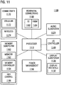
- FIG. 11 is a more detailed block diagram of an example of a device, e.g. a mobile device, in which measuring one or more neighboring inter-frequency or inter-RAT cells with a TX feedback receiver according to example implementations can be implemented.
- Device 1100 represents a mobile computing device, such as a computing tablet, a mobile phone or smartphone, a wireless-enabled e-reader, wearable computing device, or other mobile device. It will be understood that certain of the components are shown generally, and not all components of such a device are shown in device 1100.
- Device 1100 includes processor 1110, which performs the primary processing operations of device 1100.
- Processor 1110 can include one or more physical devices, such as microprocessors, application processors, microcontrollers, programmable logic devices, or other processing means.
- the processing operations performed by processor 1110 include the execution of an operating platform or operating system on which applications and/or device functions are executed.
- the processing operations include operations related to I/O (input/output) with a human user or with other devices, operations related to power management, and/or operations related to connecting device 1100 to another device.
- the processing operations can also include operations related to audio I/O and/or display I/O.
- device 1100 includes audio subsystem 1120, which represents hardware (e.g., audio hardware and audio circuits) and software (e.g., drivers, codecs) components associated with providing audio functions to the computing device. Audio functions can include speaker and/or headphone output, as well as microphone input. Devices for such functions can be integrated into device 1100, or connected to device 1100. In one embodiment, a user interacts with device 1100 by providing audio commands that are received and processed by processor 1110.
- hardware e.g., audio hardware and audio circuits
- software e.g., drivers, codecs
- Display subsystem 1130 represents hardware (e.g., display devices) and software (e.g., drivers) components that provide a visual and/or tactile display for a user to interact with the computing device.
- Display subsystem 1130 includes display interface 1132, which includes the particular screen or hardware device used to provide a display to a user.
- display interface 1132 includes logic separate from processor 1110 to perform at least some processing related to the display.
- display subsystem 1130 includes a touchscreen device that provides both output and input to a user.
- display subsystem 1130 includes a high definition (HD) display that provides an output to a user.
- High definition can refer to a display having a pixel density of approximately 100 PPI (pixels per inch) or greater, and can include formats such as full HD (e.g., 1080p), retina displays, 4K (ultra high definition or UHD), or others.
- I/O controller 1140 represents hardware devices and software components related to interaction with a user. I/O controller 1140 can operate to manage hardware that is part of audio subsystem 1120 and/or display subsystem 1130. Additionally, I/O controller 1140 illustrates a connection point for additional devices that connect to device 1100 through which a user might interact with the system. For example, devices that can be attached to device 1100 might include microphone devices, speaker or stereo systems, video systems or other display device, keyboard or keypad devices, or other I/O devices for use with specific applications such as card readers or other devices.
- I/O controller 1140 can interact with audio subsystem 1120 and/or display subsystem 1130.
- input through a microphone or other audio device can provide input or commands for one or more applications or functions of device 1100.
- audio output can be provided instead of or in addition to display output.
- display subsystem includes a touchscreen
- the display device also acts as an input device, which can be at least partially managed by I/O controller 1140.
- I/O controller 1140 manages devices such as accelerometers, cameras, light sensors or other environmental sensors, gyroscopes, global positioning system (GPS), or other hardware that can be included in device 1100.
- the input can be part of direct user interaction, as well as providing environmental input to the system to influence its operations (such as filtering for noise, adjusting displays for brightness detection, applying a flash for a camera, or other features).
- device 1100 includes power management 1150 that manages battery power usage, charging of the battery, and features related to power saving operation.
- Memory subsystem 1160 includes memory device(s) 1162 for storing information in device 1100.
- Memory subsystem 1160 can include nonvolatile (state does not change if power to the memory device is interrupted) and/or volatile (state is indeterminate if power to the memory device is interrupted) memory devices.
- Memory 1160 can store application data, user data, music, photos, documents, or other data, as well as system data (whether long-term or temporary) related to the execution of the applications and functions of system 1100.
- memory subsystem 1160 includes memory controller 1164 (which could also be considered part of the control of system 1100, and could potentially be considered part of processor 1110).
- Memory controller 1164 includes a scheduler to generate and issue commands to memory device 1162.
- Connectivity 1170 includes hardware devices (e.g., wireless and/or wired connectors and communication hardware) and software components (e.g., drivers, protocol stacks) to enable device 1100 to communicate with external devices.
- the external device could be separate devices, such as other computing devices, wireless access points or base stations, as well as peripherals such as headsets, printers, or other devices.
- Connectivity 1170 can include multiple different types of connectivity.
- device 1100 is illustrated with cellular connectivity 1172 and wireless connectivity 1174.
- Cellular connectivity 1172 refers generally to cellular network connectivity provided by wireless carriers, such as provided via GSM (global system for mobile communications) or variations or derivatives, CDMA (code division multiple access) or variations or derivatives, TDM (time division multiplexing) or variations or derivatives, LTE (long term evolution - also referred to as "4G”), or other cellular service standards.
- Wireless connectivity 1174 refers to wireless connectivity that is not cellular, and can include personal area networks (such as Bluetooth), local area networks (such as WiFi), and/or wide area networks (such as WiMax), or other wireless communication, such as NFC.
- Wireless communication refers to transfer of data through the use of modulated electromagnetic radiation through a non-solid medium. Wired communication occurs through a solid communication medium.
- Cellular connectivity 1172 and/or wireless connectivity 1174 can implement example transceivers of the present disclosure for measuring one or more neighboring inter-frequency or inter-RAT cells with a TX feedback receiver.
- Peripheral connections 1180 include hardware interfaces and connectors, as well as software components (e.g., drivers, protocol stacks) to make peripheral connections. It will be understood that device 1100 could both be a peripheral device ("to" 1182) to other computing devices, as well as have peripheral devices ("from” 1184) connected to it. Device 1100 commonly has a "docking" connector to connect to other computing devices for purposes such as managing (e.g., downloading and/or uploading, changing, synchronizing) content on device 1100. Additionally, a docking connector can allow device 1100 to connect to certain peripherals that allow device 1100 to control content output, for example, to audiovisual or other systems.
- software components e.g., drivers, protocol stacks
- device 1100 can make peripheral connections 1180 via common or standards-based connectors.
- USB Universal Serial Bus
- MDP MiniDisplayPort
- HDMI High Definition Multimedia Interface
- Firewire or other type.
- Examples may further be a computer program having a program code for performing one or more of the above methods, when the computer program is executed on a computer or processor. Steps, operations or processes of various above-described methods may be performed by programmed computers or processors. Examples may also cover program storage devices such as digital data storage media, which are machine, processor or computer readable and encode machine-executable, processor-executable or computer-executable programs of instructions. The instructions perform or cause performing some or all of the acts of the above-described methods.
- the program storage devices may comprise or be, for instance, digital memories, magnetic storage media such as magnetic disks and magnetic tapes, hard drives, or optically readable digital data storage media.
- a functional block denoted as "means for " performing a certain function may refer to a circuit that is configured to perform a certain function.
- a "means for s.th.” may be implemented as a "means configured to or suited for s.th.”, such as a device or a circuit configured to or suited for the respective task.
- Functions of various elements shown in the figures may be implemented in the form of dedicated hardware, such as “a signal provider”, “a signal processing unit”, “a processor”, “a controller”, etc. as well as hardware capable of executing software in association with appropriate software.
- a processor the functions may be provided by a single dedicated processor, by a single shared processor, or by a plurality of individual processors, some of which or all of which may be shared.
- processor or “controller” is by far not limited to hardware exclusively capable of executing software, but may include digital signal processor (DSP) hardware, network processor, application specific integrated circuit (ASIC), field programmable gate array (FPGA), read only memory (ROM) for storing software, random access memory (RAM), and nonvolatile storage.
- DSP digital signal processor
- ASIC application specific integrated circuit
- FPGA field programmable gate array
- ROM read only memory
- RAM random access memory
- nonvolatile storage Other hardware, conventional and/or custom, may also be included.
- a block diagram may, for instance, illustrate a high-level circuit diagram implementing the principles of the disclosure.
- a flow chart, a flow diagram, a state transition diagram, a pseudo code, and the like may represent various processes, operations or steps, which may, for instance, be substantially represented in computer readable medium and so executed by a computer or processor, whether or not such computer or processor is explicitly shown.
- Methods disclosed in the specification or in the claims may be implemented by a device having means for performing each of the respective acts of these methods.
Landscapes
- Engineering & Computer Science (AREA)
- Computer Networks & Wireless Communication (AREA)
- Signal Processing (AREA)
- Power Engineering (AREA)
- Physics & Mathematics (AREA)
- Nonlinear Science (AREA)
- Electromagnetism (AREA)
- Mobile Radio Communication Systems (AREA)
Claims (15)
- Équipement d'utilisateur (200) pour un système de communication sans fil, comprenant :un émetteur (210) configuré pour générer un signal d'émission (220) ;un récepteur de retour d'émetteur (230), couplé à l'émetteur et configuré pour mesurer une puissance du signal d'émission dans un premier mode de fonctionnement ; etune circuiterie de contrôle (240), configurée pour sélectionner un second mode de fonctionnement du récepteur de retour d'émetteur (230), dans lequel le récepteur de retour d'émetteur est configuré pour mesurer une ou plusieurs stations voisines inter-fréquences ou inter-RAT.
- Équipement d'utilisateur (200) selon la revendication 1, dans lequel la circuiterie de contrôle (240) est configurée pour activer simultanément l'émetteur (210) et le récepteur de retour d'émetteur (230) pendant le premier mode de fonctionnement et pour désactiver au moins une partie de l'émetteur pendant le second mode de fonctionnement.
- Équipement d'utilisateur (200) selon l'une quelconque des revendications précédentes, dans lequel le récepteur de retour d'émetteur (230) est couplé à un oscillateur local contrôlable fonctionnant à une fréquence constante pendant le second mode de fonctionnement.
- Équipement d'utilisateur (200) selon l'une quelconque des revendications précédentes, comprenant en outre :
un récepteur principal (250), configuré pour recevoir un signal en provenance d'une station de base de desserte à une ou plusieurs fréquences porteuses. - Équipement d'utilisateur (200) selon la revendication 4, dans lequel le récepteur principal (250) est configuré pour recevoir le signal en provenance de la station de base de desserte pendant que le récepteur de retour d'émetteur (230) est configuré pour mesurer simultanément la ou les stations de base voisines.
- Équipement d'utilisateur (200) selon la revendication 4, dans lequel le récepteur principal (250) et le récepteur de retour d'émetteur (230) sont configurés pour mesurer simultanément différentes stations de base voisines pendant des périodes de mesure dédiées.
- Équipement d'utilisateur (200) selon l'une quelconque des revendications précédentes, dans lequel la circuiterie de contrôle (240) est configurée pour désactiver l'émetteur (210) pendant des périodes de temps prédéfinies, et dans lequel le récepteur de retour d'émetteur (230) est configuré pour mesurer la ou les stations de base voisines pendant lesdites périodes prédéfinies.
- Équipement d'utilisateur (200) selon l'une quelconque des revendications précédentes, l'équipement d'utilisateur (200) étant configuré pour un fonctionnement en duplexage par répartition dans le temps (TDD) et le récepteur de retour d'émetteur (230) étant configuré pour mesurer la ou les stations de base voisines pendant des trames TDD en liaison descendante, ou l'équipement d'utilisateur étant configuré pour une émission discontinue et le récepteur de retour d'émetteur (230) étant configuré pour mesurer la ou les stations de base voisines pendant des périodes d'inactivité d'émission de données.
- Équipement d'utilisateur (200) selon l'une quelconque des revendications précédentes, dans lequel le récepteur de retour d'émetteur (230) est configuré pour mesurer la ou les stations de base voisines inter-fréquences ou inter-RAT dans un spectre fréquences sans licence.
- Équipement d'utilisateur (200) selon l'une quelconque des revendications précédentes, dans lequel l'émetteur (210) et le récepteur de retour d'émetteur (230) sont l'un et l'autre couplés au même oscillateur local contrôlable.
- Équipement d'utilisateur (200) selon l'une quelconque des revendications précédentes, dans lequel le récepteur de retour d'émetteur (230) comprend un premier amplificateur à faible bruit (LNA) avec une première valeur de bruit et un premier gain destinés à être utilisés pendant le premier mode de fonctionnement, et un second LNA avec une seconde valeur de bruit inférieure à la première valeur de bruit et un second gain supérieur au premier gain destinés à être utilisés pendant le second mode de fonctionnement.
- Équipement d'utilisateur (200) selon l'une quelconque des revendications précédentes, comprenant un commutateur configuré pour coupler le récepteur de retour d'émetteur (230) à une voie d'émission de l'émetteur (210) pendant le premier mode de fonctionnement, et pour coupler le récepteur de retour d'émetteur (230) à au moins une antenne pendant le second mode de fonctionnement.
- Équipement d'utilisateur (200) selon la revendication 4, dans lequel l'équipement d'utilisateur (200) est configuré pour :sélectionner, selon un indicateur de sélection de récepteur, le récepteur de retour d'émetteur (230) ou le récepteur principal (250) pour mesurer la ou les stations de base voisines pendant un intervalle de mesure inter-fréquence ou inter-RAT actuel ;mesurer, avec le récepteur sélectionné, une qualité de signal de mesure lors de la mesure de la ou des stations de base voisines ; etsi la qualité de signal de mesure dépasse un seuil prédéfini,régler l'indicateur de sélection de récepteur pour indiquer une utilisation du récepteur de retour d'émetteur (230) pour mesurer la ou les stations de base voisines pendant un intervalle de mesure inter-fréquence ou inter-RAT suivant, sinonrégler l'indicateur de sélection de récepteur pour indiquer une utilisation du récepteur principal (250) pour mesurer la ou les stations de base voisines pendant l'intervalle de mesure inter-fréquence ou inter-RAT suivant.
- Équipement d'utilisateur (200) selon l'une quelconque des revendications précédentes, dans lequel la circuiterie de contrôle (240) est configurée pour coupler le récepteur de retour d'émetteur (230) à une première antenne pendant un premier intervalle de mesure du second mode de fonctionnement, et pour coupler le récepteur de retour d'émetteur à une seconde antenne pendant un second intervalle de mesure du second mode de fonctionnement et pour combiner des mesures du premier et du second intervalle de mesure.
- Procédé (1000) de mesure d'une ou plusieurs stations de base voisines inter-fréquences ou inter-RAT avec un équipement d'utilisateur (200) d'un système de communication sans fil, l'équipement d'utilisateur comprenant un émetteur (210) configuré pour générer un signal d'émission (220), le procédé consistant à :utiliser (1010), dans un premier mode de fonctionnement, un récepteur de retour d'émetteur (230) couplé à l'émetteur (210) pendant le premier mode de fonctionnement pour mesurer une puissance du signal d'émission (220) ; etutiliser (1020), dans un second mode de fonctionnement, le récepteur de retour d'émetteur (230) pour mesurer la ou les stations de base voisines inter-fréquences ou inter-RAT.
Priority Applications (3)
| Application Number | Priority Date | Filing Date | Title |
|---|---|---|---|
| EP16191012.0A EP3301975B1 (fr) | 2016-09-28 | 2016-09-28 | Appareils et procédés de mesure de cellules voisines inter-rat ou d'interfréquence |
| US16/328,741 US10897733B2 (en) | 2016-09-28 | 2017-08-01 | Apparatuses and methods for measuring neighboring inter-frequency or inter-rat cells |
| PCT/US2017/044781 WO2018063494A1 (fr) | 2016-09-28 | 2017-08-01 | Appareils et procédés de mesure de cellules inter-fréquences ou inter-rat voisines |
Applications Claiming Priority (1)
| Application Number | Priority Date | Filing Date | Title |
|---|---|---|---|
| EP16191012.0A EP3301975B1 (fr) | 2016-09-28 | 2016-09-28 | Appareils et procédés de mesure de cellules voisines inter-rat ou d'interfréquence |
Publications (2)
| Publication Number | Publication Date |
|---|---|
| EP3301975A1 EP3301975A1 (fr) | 2018-04-04 |
| EP3301975B1 true EP3301975B1 (fr) | 2019-05-01 |
Family
ID=57018053
Family Applications (1)
| Application Number | Title | Priority Date | Filing Date |
|---|---|---|---|
| EP16191012.0A Not-in-force EP3301975B1 (fr) | 2016-09-28 | 2016-09-28 | Appareils et procédés de mesure de cellules voisines inter-rat ou d'interfréquence |
Country Status (3)
| Country | Link |
|---|---|
| US (1) | US10897733B2 (fr) |
| EP (1) | EP3301975B1 (fr) |
| WO (1) | WO2018063494A1 (fr) |
Families Citing this family (10)
| Publication number | Priority date | Publication date | Assignee | Title |
|---|---|---|---|---|
| CN111108796B (zh) * | 2017-09-28 | 2024-04-05 | 三星电子株式会社 | 用于在多个带宽部分上执行数据发射和测量的方法和网络节点 |
| US12250018B1 (en) * | 2024-09-05 | 2025-03-11 | Swiftlink Technologies Inc. | MIMO transceiver array for multi-band millimeter-wave 5G communication |
| EP3584963B1 (fr) * | 2018-06-18 | 2022-01-05 | Xilinx, Inc. | Système d'étalonnage et procédé d'étalonnage |
| US10840994B2 (en) | 2018-09-19 | 2020-11-17 | Apple Inc. | Systems and methods for opportunistic antenna selection |
| WO2020209996A1 (fr) * | 2019-04-09 | 2020-10-15 | Commscope Technologies Llc | Surveillance d'environnement radio dans une station de base à l'aide d'une puce mobile |
| WO2021029761A1 (fr) * | 2019-08-14 | 2021-02-18 | 엘지전자 주식회사 | Procédé et appareil d'émission ou de réception de signal sans fil dans un système de communication sans fil |
| US11218916B2 (en) | 2019-10-09 | 2022-01-04 | Cisco Technology, Inc. | Interfrequency handovers in shared spectrum LTE/5G systems using Wi-Fi based location |
| KR20230030345A (ko) * | 2021-08-25 | 2023-03-06 | 삼성전자주식회사 | 통신 장치, 및 이의 동작 방법 |
| CN116800292B (zh) * | 2022-03-14 | 2026-01-20 | 上海华为技术有限公司 | 无线设备及信号处理方法 |
| EP4354742A1 (fr) * | 2022-10-12 | 2024-04-17 | Nokia Technologies Oy | Réception flexible |
Family Cites Families (34)
| Publication number | Priority date | Publication date | Assignee | Title |
|---|---|---|---|---|
| KR100316691B1 (ko) * | 1999-11-10 | 2001-12-12 | 박종섭 | 스위치를 이용한 기지국 안테나 점검장치 및 방법 |
| US6741587B2 (en) * | 2002-04-02 | 2004-05-25 | Nokia Corporation | Inter-frequency measurements with MIMO terminals |
| EP1527529B1 (fr) * | 2002-08-05 | 2007-10-10 | Nokia Corporation | Diversite de transmission avec deux reseaux d'antennes a polarisation croisee |
| US20060050810A1 (en) * | 2004-07-29 | 2006-03-09 | Interdigital Technology Corporation | Hybrid transmitter architecture having high efficiency and large dynamic range |
| EP1882306B1 (fr) * | 2005-04-22 | 2013-03-27 | Nxp B.V. | Circuit integre, dispositif electronique et procede de commande d'un circuit integre |
| EP1871133B1 (fr) | 2005-08-24 | 2011-04-20 | Huawei Technologies Co., Ltd. | Procede de mesure, procede de determination les besoins en capacite de mesure et cellule de selection de services et terminal a cet effet |
| US8995502B1 (en) * | 2006-04-04 | 2015-03-31 | Apple Inc. | Transceiver with spectral analysis |
| US7778352B2 (en) * | 2006-12-21 | 2010-08-17 | Broadcom Corporation | Digital compensation for nonlinearities in a polar transmitter |
| GB2445779B (en) | 2007-01-11 | 2009-07-08 | Samsung Electronics Co Ltd | Wireless communication system |
| JP5043810B2 (ja) * | 2007-12-26 | 2012-10-10 | パナソニック株式会社 | 生体試料測定装置およびこれを備えた生体試料測定システム |
| US9236927B2 (en) * | 2010-02-25 | 2016-01-12 | Sony Corporation | Transmission apparatus and method for transmission of data in a multi-carrier broadcast system |
| US8130047B2 (en) * | 2010-04-30 | 2012-03-06 | Texas Instruments Incorporated | Open loop coarse tuning for a PLL |
| WO2012068731A1 (fr) | 2010-11-25 | 2012-05-31 | Nokia Corporation | Détection assistée par réseau sur une bande partagée pour des communications locales |
| US8565178B2 (en) * | 2010-12-03 | 2013-10-22 | Samsung Electronics Co., Ltd. | Method and apparatus for wireless communication on multiple spectrum bands |
| CN102387532B (zh) * | 2011-01-10 | 2013-12-04 | 华为技术有限公司 | 频点信息处理方法和用户设备 |
| US8489045B2 (en) * | 2011-02-02 | 2013-07-16 | Qualcomm Incorporated | Method and system for adjusting transmission power |
| US8705595B2 (en) * | 2011-05-06 | 2014-04-22 | Telefonaktiebolaget L M Ericsson (Publ) | Digital output power measurement in radio communication systems |
| WO2012173568A1 (fr) | 2011-06-17 | 2012-12-20 | Telefonaktiebolaget L M Ericsson (Publ) | Amélioration de performance de dispositif sans fil dans des réseaux hétérogènes |
| US9338664B2 (en) * | 2012-02-22 | 2016-05-10 | Mediatek Singapore Pte. Ltd. | Wireless communication unit, integrated circuit and method therefor |
| EP2820891B1 (fr) * | 2012-02-28 | 2021-08-04 | Nokia Technologies Oy | Modèle de mesure pour la recherche de petites cellules |
| US9038542B2 (en) * | 2012-03-23 | 2015-05-26 | B & B Metals, Inc. | Tie plate separator and method thereof |
| US20140036710A1 (en) | 2012-08-06 | 2014-02-06 | Qualcomm Incorporated | Inter-rat measurements for a dual-sim dual-active device |
| WO2014171885A1 (fr) * | 2013-04-16 | 2014-10-23 | Telefonaktiebolaget L M Ericsson (Publ) | Procede, nœud de reseau, programme d'ordinateur et produit programme d'ordinateur pour une cellule combinee |
| US20150118980A1 (en) | 2013-10-29 | 2015-04-30 | Qualcomm Incorporated | Transmitter (tx) residual sideband (rsb) and local oscillator (lo) leakage calibration using a reconfigurable tone generator (tg) and lo paths |
| KR101748304B1 (ko) * | 2014-01-24 | 2017-06-16 | 후아웨이 테크놀러지 컴퍼니 리미티드 | 측정 방법, 구성 방법, 관련 장치 및 시스템 |
| US20150280946A1 (en) * | 2014-03-27 | 2015-10-01 | Qualcomm Incorporated | Feedback receive path with low-if mode |
| US10033343B2 (en) | 2014-03-31 | 2018-07-24 | Qualcomm Incorporated | Spectrum sensing radio receiver |
| US9521598B2 (en) | 2014-04-23 | 2016-12-13 | Apple Inc. | Performing handover from a second generation RAT to a fourth generation RAT |
| US20160142950A1 (en) * | 2014-11-13 | 2016-05-19 | Qualcomm Incorporated | Hybrid-antenna mode of an apparatus configured for wireless communication |
| US20160373948A1 (en) * | 2015-06-18 | 2016-12-22 | Qualcomm Incorporated | Performing inter-frequency and inter radio access technology measurements in a multi subscriber identity module multi active mobile communication device |
| US9602149B1 (en) * | 2015-12-21 | 2017-03-21 | Intel IP Corporation | Architecture and control of hybrid coupler based analog self-interference cancellation |
| TWI594259B (zh) * | 2016-05-13 | 2017-08-01 | 群聯電子股份有限公司 | 記憶體儲存裝置及其電源管理方法 |
| US10165490B1 (en) * | 2016-12-19 | 2018-12-25 | Mbit Wireless, Inc. | Method and apparatus for collaborative measurement information transmission |
| US10517003B2 (en) * | 2016-12-28 | 2019-12-24 | Qualcomm Incorporated | Systems and methods for maintaining service on multiple SIMs in a wireless communication device operating in a multi-SIM multi-standby (MSMS) mode |
-
2016
- 2016-09-28 EP EP16191012.0A patent/EP3301975B1/fr not_active Not-in-force
-
2017
- 2017-08-01 WO PCT/US2017/044781 patent/WO2018063494A1/fr not_active Ceased
- 2017-08-01 US US16/328,741 patent/US10897733B2/en not_active Expired - Fee Related
Non-Patent Citations (1)
| Title |
|---|
| None * |
Also Published As
| Publication number | Publication date |
|---|---|
| EP3301975A1 (fr) | 2018-04-04 |
| WO2018063494A1 (fr) | 2018-04-05 |
| US20190200270A1 (en) | 2019-06-27 |
| US10897733B2 (en) | 2021-01-19 |
Similar Documents
| Publication | Publication Date | Title |
|---|---|---|
| EP3301975B1 (fr) | Appareils et procédés de mesure de cellules voisines inter-rat ou d'interfréquence | |
| US11133839B2 (en) | Detection of intermodulation issues and transmission scheme configuration to remedy intermodulation issues | |
| US9867207B2 (en) | Simultaneous scheduling request transmission in dual connectivity | |
| JP7181944B2 (ja) | デフォルトのpucch及びsrsビームの判定 | |
| US11265789B2 (en) | Method and apparatus for managing co-existence interference | |
| US9356744B2 (en) | Method for deactivated secondary cell measurement and communications apparatus utilizing the same | |
| CN107409027A (zh) | 用于载波聚合测量间隙的用户设备射频和频带能力 | |
| US10582360B2 (en) | Personal area network communication for wearable devices | |
| WO2017146758A1 (fr) | Dispositif et procédé d'utilisation d'une configuration brrs | |
| CN112788788A (zh) | 用于快速单dci和多dci模式切换的系统和方法 | |
| US11496907B2 (en) | Method and system for interference cancellation in spectrum sharing radio environments | |
| US20220329300A1 (en) | Methods and systems for dynamic interference mitigation | |
| US11558158B2 (en) | Methods and devices for dynamically avoiding radio frequency interference | |
| WO2018031136A1 (fr) | Procédés et dispositifs pour résoudre la disparité de puissance d'émission | |
| EP3353924B1 (fr) | Mappage de symboles de répétition de canal physique de diffusion (pbch) pour une communication de type machine | |
| WO2017180194A1 (fr) | Appareil et procédé de mesurage de ressource radio d'un ue à accès assisté par licence et de mesurage de csi | |
| WO2018101915A1 (fr) | Mesures de mobilité dans des systèmes 5g | |
| US20190116549A1 (en) | License assisted access (laa) measurement requirements | |
| US11310082B2 (en) | Devices and methods for estimating noise covariance | |
| US20250112659A1 (en) | Methods and devices to perform spectrum sensing | |
| WO2017023354A1 (fr) | Mesure de gestion de ressources radio et protocole de commande de ressources radio pour un accès partagé sous licence | |
| WO2025172049A1 (fr) | Appareil, procédé et programme informatique | |
| WO2025172050A1 (fr) | Appareil, procédé et programme informatique | |
| WO2025011787A1 (fr) | Atténuation d'interférence inter-sim | |
| EP3437051A1 (fr) | Communication fiable en bandes à accès à autorisations partagées |
Legal Events
| Date | Code | Title | Description |
|---|---|---|---|
| REG | Reference to a national code |
Ref country code: DE Ref legal event code: R138 Ref document number: 202016008749 Country of ref document: DE Free format text: GERMAN DOCUMENT NUMBER IS 602016013104 |
|
| PUAI | Public reference made under article 153(3) epc to a published international application that has entered the european phase |
Free format text: ORIGINAL CODE: 0009012 |
|
| STAA | Information on the status of an ep patent application or granted ep patent |
Free format text: STATUS: THE APPLICATION HAS BEEN PUBLISHED |
|
| AK | Designated contracting states |
Kind code of ref document: A1 Designated state(s): AL AT BE BG CH CY CZ DE DK EE ES FI FR GB GR HR HU IE IS IT LI LT LU LV MC MK MT NL NO PL PT RO RS SE SI SK SM TR |
|
| AX | Request for extension of the european patent |
Extension state: BA ME |
|
| STAA | Information on the status of an ep patent application or granted ep patent |
Free format text: STATUS: REQUEST FOR EXAMINATION WAS MADE |
|
| 17P | Request for examination filed |
Effective date: 20181004 |
|
| RBV | Designated contracting states (corrected) |
Designated state(s): AL AT BE BG CH CY CZ DE DK EE ES FI FR GB GR HR HU IE IS IT LI LT LU LV MC MK MT NL NO PL PT RO RS SE SI SK SM TR |
|
| RIC1 | Information provided on ipc code assigned before grant |
Ipc: H04B 1/3805 20150101ALI20181105BHEP Ipc: H04W 36/30 20090101AFI20181105BHEP |
|
| GRAP | Despatch of communication of intention to grant a patent |
Free format text: ORIGINAL CODE: EPIDOSNIGR1 |
|
| STAA | Information on the status of an ep patent application or granted ep patent |
Free format text: STATUS: GRANT OF PATENT IS INTENDED |
|
| INTG | Intention to grant announced |
Effective date: 20181220 |
|
| GRAS | Grant fee paid |
Free format text: ORIGINAL CODE: EPIDOSNIGR3 |
|
| GRAA | (expected) grant |
Free format text: ORIGINAL CODE: 0009210 |
|
| STAA | Information on the status of an ep patent application or granted ep patent |
Free format text: STATUS: THE PATENT HAS BEEN GRANTED |
|
| AK | Designated contracting states |
Kind code of ref document: B1 Designated state(s): AL AT BE BG CH CY CZ DE DK EE ES FI FR GB GR HR HU IE IS IT LI LT LU LV MC MK MT NL NO PL PT RO RS SE SI SK SM TR |
|
| REG | Reference to a national code |
Ref country code: GB Ref legal event code: FG4D |
|
| REG | Reference to a national code |
Ref country code: CH Ref legal event code: EP Ref country code: AT Ref legal event code: REF Ref document number: 1128602 Country of ref document: AT Kind code of ref document: T Effective date: 20190515 |
|
| REG | Reference to a national code |
Ref country code: DE Ref legal event code: R096 Ref document number: 602016013104 Country of ref document: DE |
|
| REG | Reference to a national code |
Ref country code: IE Ref legal event code: FG4D |
|
| REG | Reference to a national code |
Ref country code: NL Ref legal event code: FP |
|
| REG | Reference to a national code |
Ref country code: LT Ref legal event code: MG4D |
|
| PG25 | Lapsed in a contracting state [announced via postgrant information from national office to epo] |
Ref country code: ES Free format text: LAPSE BECAUSE OF FAILURE TO SUBMIT A TRANSLATION OF THE DESCRIPTION OR TO PAY THE FEE WITHIN THE PRESCRIBED TIME-LIMIT Effective date: 20190501 Ref country code: PT Free format text: LAPSE BECAUSE OF FAILURE TO SUBMIT A TRANSLATION OF THE DESCRIPTION OR TO PAY THE FEE WITHIN THE PRESCRIBED TIME-LIMIT Effective date: 20190901 Ref country code: HR Free format text: LAPSE BECAUSE OF FAILURE TO SUBMIT A TRANSLATION OF THE DESCRIPTION OR TO PAY THE FEE WITHIN THE PRESCRIBED TIME-LIMIT Effective date: 20190501 Ref country code: SE Free format text: LAPSE BECAUSE OF FAILURE TO SUBMIT A TRANSLATION OF THE DESCRIPTION OR TO PAY THE FEE WITHIN THE PRESCRIBED TIME-LIMIT Effective date: 20190501 Ref country code: AL Free format text: LAPSE BECAUSE OF FAILURE TO SUBMIT A TRANSLATION OF THE DESCRIPTION OR TO PAY THE FEE WITHIN THE PRESCRIBED TIME-LIMIT Effective date: 20190501 Ref country code: FI Free format text: LAPSE BECAUSE OF FAILURE TO SUBMIT A TRANSLATION OF THE DESCRIPTION OR TO PAY THE FEE WITHIN THE PRESCRIBED TIME-LIMIT Effective date: 20190501 Ref country code: NO Free format text: LAPSE BECAUSE OF FAILURE TO SUBMIT A TRANSLATION OF THE DESCRIPTION OR TO PAY THE FEE WITHIN THE PRESCRIBED TIME-LIMIT Effective date: 20190801 Ref country code: LT Free format text: LAPSE BECAUSE OF FAILURE TO SUBMIT A TRANSLATION OF THE DESCRIPTION OR TO PAY THE FEE WITHIN THE PRESCRIBED TIME-LIMIT Effective date: 20190501 |
|
| PG25 | Lapsed in a contracting state [announced via postgrant information from national office to epo] |
Ref country code: RS Free format text: LAPSE BECAUSE OF FAILURE TO SUBMIT A TRANSLATION OF THE DESCRIPTION OR TO PAY THE FEE WITHIN THE PRESCRIBED TIME-LIMIT Effective date: 20190501 Ref country code: BG Free format text: LAPSE BECAUSE OF FAILURE TO SUBMIT A TRANSLATION OF THE DESCRIPTION OR TO PAY THE FEE WITHIN THE PRESCRIBED TIME-LIMIT Effective date: 20190801 Ref country code: GR Free format text: LAPSE BECAUSE OF FAILURE TO SUBMIT A TRANSLATION OF THE DESCRIPTION OR TO PAY THE FEE WITHIN THE PRESCRIBED TIME-LIMIT Effective date: 20190802 Ref country code: LV Free format text: LAPSE BECAUSE OF FAILURE TO SUBMIT A TRANSLATION OF THE DESCRIPTION OR TO PAY THE FEE WITHIN THE PRESCRIBED TIME-LIMIT Effective date: 20190501 |
|
| REG | Reference to a national code |
Ref country code: AT Ref legal event code: MK05 Ref document number: 1128602 Country of ref document: AT Kind code of ref document: T Effective date: 20190501 |
|
| PG25 | Lapsed in a contracting state [announced via postgrant information from national office to epo] |
Ref country code: IS Free format text: LAPSE BECAUSE OF FAILURE TO SUBMIT A TRANSLATION OF THE DESCRIPTION OR TO PAY THE FEE WITHIN THE PRESCRIBED TIME-LIMIT Effective date: 20190901 |
|
| PG25 | Lapsed in a contracting state [announced via postgrant information from national office to epo] |
Ref country code: AT Free format text: LAPSE BECAUSE OF FAILURE TO SUBMIT A TRANSLATION OF THE DESCRIPTION OR TO PAY THE FEE WITHIN THE PRESCRIBED TIME-LIMIT Effective date: 20190501 Ref country code: EE Free format text: LAPSE BECAUSE OF FAILURE TO SUBMIT A TRANSLATION OF THE DESCRIPTION OR TO PAY THE FEE WITHIN THE PRESCRIBED TIME-LIMIT Effective date: 20190501 Ref country code: DK Free format text: LAPSE BECAUSE OF FAILURE TO SUBMIT A TRANSLATION OF THE DESCRIPTION OR TO PAY THE FEE WITHIN THE PRESCRIBED TIME-LIMIT Effective date: 20190501 Ref country code: SK Free format text: LAPSE BECAUSE OF FAILURE TO SUBMIT A TRANSLATION OF THE DESCRIPTION OR TO PAY THE FEE WITHIN THE PRESCRIBED TIME-LIMIT Effective date: 20190501 Ref country code: RO Free format text: LAPSE BECAUSE OF FAILURE TO SUBMIT A TRANSLATION OF THE DESCRIPTION OR TO PAY THE FEE WITHIN THE PRESCRIBED TIME-LIMIT Effective date: 20190501 Ref country code: CZ Free format text: LAPSE BECAUSE OF FAILURE TO SUBMIT A TRANSLATION OF THE DESCRIPTION OR TO PAY THE FEE WITHIN THE PRESCRIBED TIME-LIMIT Effective date: 20190501 |
|
| REG | Reference to a national code |
Ref country code: DE Ref legal event code: R097 Ref document number: 602016013104 Country of ref document: DE |
|
| PG25 | Lapsed in a contracting state [announced via postgrant information from national office to epo] |
Ref country code: SM Free format text: LAPSE BECAUSE OF FAILURE TO SUBMIT A TRANSLATION OF THE DESCRIPTION OR TO PAY THE FEE WITHIN THE PRESCRIBED TIME-LIMIT Effective date: 20190501 Ref country code: IT Free format text: LAPSE BECAUSE OF FAILURE TO SUBMIT A TRANSLATION OF THE DESCRIPTION OR TO PAY THE FEE WITHIN THE PRESCRIBED TIME-LIMIT Effective date: 20190501 |
|
| PLBE | No opposition filed within time limit |
Free format text: ORIGINAL CODE: 0009261 |
|
| STAA | Information on the status of an ep patent application or granted ep patent |
Free format text: STATUS: NO OPPOSITION FILED WITHIN TIME LIMIT |
|
| PG25 | Lapsed in a contracting state [announced via postgrant information from national office to epo] |
Ref country code: TR Free format text: LAPSE BECAUSE OF FAILURE TO SUBMIT A TRANSLATION OF THE DESCRIPTION OR TO PAY THE FEE WITHIN THE PRESCRIBED TIME-LIMIT Effective date: 20190501 |
|
| 26N | No opposition filed |
Effective date: 20200204 |
|
| PG25 | Lapsed in a contracting state [announced via postgrant information from national office to epo] |
Ref country code: PL Free format text: LAPSE BECAUSE OF FAILURE TO SUBMIT A TRANSLATION OF THE DESCRIPTION OR TO PAY THE FEE WITHIN THE PRESCRIBED TIME-LIMIT Effective date: 20190501 |
|
| PG25 | Lapsed in a contracting state [announced via postgrant information from national office to epo] |
Ref country code: SI Free format text: LAPSE BECAUSE OF FAILURE TO SUBMIT A TRANSLATION OF THE DESCRIPTION OR TO PAY THE FEE WITHIN THE PRESCRIBED TIME-LIMIT Effective date: 20190501 Ref country code: MC Free format text: LAPSE BECAUSE OF FAILURE TO SUBMIT A TRANSLATION OF THE DESCRIPTION OR TO PAY THE FEE WITHIN THE PRESCRIBED TIME-LIMIT Effective date: 20190501 |
|
| REG | Reference to a national code |
Ref country code: CH Ref legal event code: PL |
|
| REG | Reference to a national code |
Ref country code: DE Ref legal event code: R082 Ref document number: 602016013104 Country of ref document: DE Representative=s name: WITHERS & ROGERS LLP, DE Ref country code: DE Ref legal event code: R081 Ref document number: 602016013104 Country of ref document: DE Owner name: APPLE INC., CUPERTINO, US Free format text: FORMER OWNER: INTEL IP CORPORATION, SANTA CLARA, CALIF., US Ref country code: DE Ref legal event code: R081 Ref document number: 602016013104 Country of ref document: DE Owner name: APPLE INC., CUPERTINO, US Free format text: FORMER OWNER: INTEL IP CORPORATION, SANTA CLARA, CA, US |
|
| PG25 | Lapsed in a contracting state [announced via postgrant information from national office to epo] |
Ref country code: LI Free format text: LAPSE BECAUSE OF NON-PAYMENT OF DUE FEES Effective date: 20190930 Ref country code: CH Free format text: LAPSE BECAUSE OF NON-PAYMENT OF DUE FEES Effective date: 20190930 Ref country code: IE Free format text: LAPSE BECAUSE OF NON-PAYMENT OF DUE FEES Effective date: 20190928 Ref country code: LU Free format text: LAPSE BECAUSE OF NON-PAYMENT OF DUE FEES Effective date: 20190928 |
|
| REG | Reference to a national code |
Ref country code: BE Ref legal event code: MM Effective date: 20190930 |
|
| PG25 | Lapsed in a contracting state [announced via postgrant information from national office to epo] |
Ref country code: BE Free format text: LAPSE BECAUSE OF NON-PAYMENT OF DUE FEES Effective date: 20190930 |
|
| REG | Reference to a national code |
Ref country code: NL Ref legal event code: PD Owner name: APPLE INC.; US Free format text: DETAILS ASSIGNMENT: CHANGE OF OWNER(S), ASSIGNMENT; FORMER OWNER NAME: INTEL IP CORPORATION Effective date: 20200917 |
|
| REG | Reference to a national code |
Ref country code: GB Ref legal event code: 732E Free format text: REGISTERED BETWEEN 20201105 AND 20201111 |
|
| PG25 | Lapsed in a contracting state [announced via postgrant information from national office to epo] |
Ref country code: CY Free format text: LAPSE BECAUSE OF FAILURE TO SUBMIT A TRANSLATION OF THE DESCRIPTION OR TO PAY THE FEE WITHIN THE PRESCRIBED TIME-LIMIT Effective date: 20190501 |
|
| PG25 | Lapsed in a contracting state [announced via postgrant information from national office to epo] |
Ref country code: HU Free format text: LAPSE BECAUSE OF FAILURE TO SUBMIT A TRANSLATION OF THE DESCRIPTION OR TO PAY THE FEE WITHIN THE PRESCRIBED TIME-LIMIT; INVALID AB INITIO Effective date: 20160928 Ref country code: MT Free format text: LAPSE BECAUSE OF FAILURE TO SUBMIT A TRANSLATION OF THE DESCRIPTION OR TO PAY THE FEE WITHIN THE PRESCRIBED TIME-LIMIT Effective date: 20190501 |
|
| PGFP | Annual fee paid to national office [announced via postgrant information from national office to epo] |
Ref country code: FR Payment date: 20210812 Year of fee payment: 6 Ref country code: NL Payment date: 20210915 Year of fee payment: 6 |
|
| PGFP | Annual fee paid to national office [announced via postgrant information from national office to epo] |
Ref country code: DE Payment date: 20210818 Year of fee payment: 6 Ref country code: GB Payment date: 20210818 Year of fee payment: 6 |
|
| PG25 | Lapsed in a contracting state [announced via postgrant information from national office to epo] |
Ref country code: MK Free format text: LAPSE BECAUSE OF FAILURE TO SUBMIT A TRANSLATION OF THE DESCRIPTION OR TO PAY THE FEE WITHIN THE PRESCRIBED TIME-LIMIT Effective date: 20190501 |
|
| REG | Reference to a national code |
Ref country code: DE Ref legal event code: R119 Ref document number: 602016013104 Country of ref document: DE |
|
| REG | Reference to a national code |
Ref country code: NL Ref legal event code: MM Effective date: 20221001 |
|
| GBPC | Gb: european patent ceased through non-payment of renewal fee |
Effective date: 20220928 |
|
| PG25 | Lapsed in a contracting state [announced via postgrant information from national office to epo] |
Ref country code: NL Free format text: LAPSE BECAUSE OF NON-PAYMENT OF DUE FEES Effective date: 20221001 |
|
| PG25 | Lapsed in a contracting state [announced via postgrant information from national office to epo] |
Ref country code: FR Free format text: LAPSE BECAUSE OF NON-PAYMENT OF DUE FEES Effective date: 20220930 Ref country code: DE Free format text: LAPSE BECAUSE OF NON-PAYMENT OF DUE FEES Effective date: 20230401 |
|
| PG25 | Lapsed in a contracting state [announced via postgrant information from national office to epo] |
Ref country code: GB Free format text: LAPSE BECAUSE OF NON-PAYMENT OF DUE FEES Effective date: 20220928 |