EP3302131B1 - Structures et procédés de ventilation de chaussure - Google Patents
Structures et procédés de ventilation de chaussure Download PDFInfo
- Publication number
- EP3302131B1 EP3302131B1 EP16808192.5A EP16808192A EP3302131B1 EP 3302131 B1 EP3302131 B1 EP 3302131B1 EP 16808192 A EP16808192 A EP 16808192A EP 3302131 B1 EP3302131 B1 EP 3302131B1
- Authority
- EP
- European Patent Office
- Prior art keywords
- footwear
- ventilation channel
- toe cap
- ventilation
- article
- Prior art date
- Legal status (The legal status is an assumption and is not a legal conclusion. Google has not performed a legal analysis and makes no representation as to the accuracy of the status listed.)
- Active
Links
Images


Classifications
-
- A—HUMAN NECESSITIES
- A43—FOOTWEAR
- A43B—CHARACTERISTIC FEATURES OF FOOTWEAR; PARTS OF FOOTWEAR
- A43B23/00—Uppers; Boot legs; Stiffeners; Other single parts of footwear
- A43B23/08—Heel stiffeners; Toe stiffeners
- A43B23/081—Toe stiffeners
-
- A—HUMAN NECESSITIES
- A43—FOOTWEAR
- A43B—CHARACTERISTIC FEATURES OF FOOTWEAR; PARTS OF FOOTWEAR
- A43B23/00—Uppers; Boot legs; Stiffeners; Other single parts of footwear
- A43B23/02—Uppers; Boot legs
- A43B23/0245—Uppers; Boot legs characterised by the constructive form
- A43B23/028—Resilient uppers, e.g. shock absorbing
-
- A—HUMAN NECESSITIES
- A43—FOOTWEAR
- A43B—CHARACTERISTIC FEATURES OF FOOTWEAR; PARTS OF FOOTWEAR
- A43B23/00—Uppers; Boot legs; Stiffeners; Other single parts of footwear
- A43B23/26—Tongues for shoes
-
- A—HUMAN NECESSITIES
- A43—FOOTWEAR
- A43B—CHARACTERISTIC FEATURES OF FOOTWEAR; PARTS OF FOOTWEAR
- A43B7/00—Footwear with health or hygienic arrangements
- A43B7/06—Footwear with health or hygienic arrangements ventilated
- A43B7/08—Footwear with health or hygienic arrangements ventilated with air-holes, with or without closures
- A43B7/084—Footwear with health or hygienic arrangements ventilated with air-holes, with or without closures characterised by the location of the holes
- A43B7/085—Footwear with health or hygienic arrangements ventilated with air-holes, with or without closures characterised by the location of the holes in the upper
-
- A—HUMAN NECESSITIES
- A43—FOOTWEAR
- A43B—CHARACTERISTIC FEATURES OF FOOTWEAR; PARTS OF FOOTWEAR
- A43B7/00—Footwear with health or hygienic arrangements
- A43B7/32—Footwear with health or hygienic arrangements with shock-absorbing means
Definitions
- the present invention relates to articles of footwear, in particular articles of footwear having improved ventilation characteristics.
- a first aspect of the present invention includes an article of footwear as disclosed in claim 1.
- a second aspect of the invention includes a protective toe cap for an article of footwear as disclosed in claim 12.
- the toe cap is rigid and has strength characteristics sufficient to satisfy ASTM F2413-11.
- the inventions disclosed herein include, in general, various types of protective footwear that utilize ventilation and/or safety structures to provide improved breathability and safety for a user of the footwear.
- the footwear disclosed herein utilizes an improved protective toe cap 20, as shown in Figs. 1-5 , along with various vents and/or heat channels to provide footwear 10 with effective protection for a user's toe area, as well as improved ventilation.
- Such footwear 10 may also use other protective structures, such as a metatarsal guard 70 that itself has vents or other mechanisms, for providing ventilation.
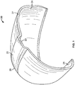
- Figs. 1-5 are various views of a toe cap 20, in accordance with an embodiment of the invention.
- Toe cap 20 is shaped to fully cover a user's toes and provide protection therefor.
- toe cap 20 is shaped as a hemi-dome in some embodiments.
- Toe cap 20 includes an open underside 24 sized to accommodate a user's toes, and has a protrusion 22 forming a ventilation channel 23 along underside 24. Although a single protrusion 22 is shown, multiple protrusions forming multiple ventilation channels are equally possible and contemplated by the present invention.
- Such protrusions may be arranged directly adjacent one another (e.g ., in the center of toe cap 20), or may be spaced apart from each other (e.g ., a protrusion substantially centered on toe cap 20, as shown in Fig. 1 , and one or more protrusions along the sides of toe cap 20).
- Protrusion 22 of Figs. 1-5 extends from a midfoot side 27 of toe cap 20 towards a forefoot side 28 of toe cap 20 and tapers in the direction of forefoot side 28.
- a height of channel 23 is at a maximum at midfoot side 27 of toe cap 20 and progressively decreases in the direction of forefoot side 28 until protrusion 22 and channel 23 disappear along underside 24 of toe cap 20.
- protrusion 22 is shaped as a quadrangle, although it could be semi-circular, triangular, hexagonal, pentagonal, polygonal, or any other shape that adequately provides a ventilation channel 23.
- Toe cap 20 also includes a lower lip 26 that extends around the perimeter of underside 24. Lip 26 may be positioned in footwear under a user's foot and be utilized for attaching toe cap 20 to such footwear, as described in more detail below.
- Toe cap 20 is, in an embodiment, composed of a metal or metal alloy material (e.g ., titanium) or any other material of a sufficient strength to satisfy safety standards for protective footwear, such as ASTM F2413-11.
- Toe cap 20 can be incorporated into a variety of different types of footwear, with or without additional ventilation characteristics, to allow for improved ventilation and breathability in the footwear.
- Various embodiments of such footwear are shown throughout in Figs. 6-16 (with certain components of such footwear shown in isolation in those figures).
- FIG. 6 a first variant of footwear 110 is shown in Fig. 6 .
- Footwear 110 includes all standard aspects of normal footwear, including but not limited to an outsole 117, an upper 119 attached to outsole 117, forefoot 112, arch 114, and heel 116 regions, and a tongue 118 forming part of upper 119.
- footwear 110 includes such components as is apparent in the figures ( e.g ., laces, etc.)
- footwear 110 also includes a toe cap 20 embedded within its forefoot region 112.
- Toe cap 20 is incorporated into the toe region of footwear 110 and is arranged with its lip 26 adjacent outsole 117 and its protrusion 22 positioned above the user's toes.
- Toe cap 20 may therefore provide protection for a user's toes against, for example, a falling object and also allow for improved ventilation via its protrusion 22 and ventilation channel 23.
- tongue 118 of footwear 110 may also include an air vent channel 30 that, in an embodiment, forms a continuation of channel 23 of protrusion 22 of toe cap 20.
- tongue 118 may include an air vent channel 30 that extends longitudinally along tongue 118, and protrusion 22 may be shaped and sized to be positioned within vent channel 30 of tongue 118 so that a continuous air vent channel is formed along forefoot region 112 and arch region 114 of footwear 110.
- air vent channel 30 of tongue 118 terminates in a heat egress port 32 having a series of perforations 36 for allowing heat, moisture, etc. to escape channel 30.
- heat and/or moisture trapped in forefoot region 112 of footwear 110 may be allowed to escape through channel 23 of toe cap 20, into channel 30 of tongue 118 (which in an embodiment form a substantially continuous channel), and out of heat egress port 32.
- air vent channel 30 of tongue 118 may be open in the direction of a user's foot (e.g., like channel 23 of toe cap 20), or in other embodiments it may be closed by way of a mesh or other fabric covering vent channel 30.
- Meshes or other breathable fabrics may increase the comfort level of footwear 110 in the area of channel 30 of tongue 118 and channel 23 of toe cap 20. Indeed, to be clear, such meshes and fabrics as described above may extend over both channel 30 of tongue 118 and channel 23 of toe cap 20, in certain embodiments.
- air vent channel 30 may be formed on a leather overlay component 40 that is engaged with a leather underlay 38 attached under the eyestay quarter of footwear 110.
- footwear 110 may provide improved ventilation for safety/protective footwear by allowing heat to escape footwear 110 through channel 23 of toe cap 20, into air vent channel 30 of tongue 118, and out of heat egress port 32.
- toe cap 20 provides adequate safety for a user's toes and protects the toes from injury.
- FIG. 7 A second variant of footwear 110' is shown in Fig. 7 . Due to the similarities between footwear 110 of Fig. 6 and footwear 110' of Fig. 7 , like reference numerals refer to like elements in this embodiment (although a prime designation is added to the reference numerals of Fig. 7 ), and predominantly the differences between footwear 110, 110' are discussed below.
- Footwear 110' is different from footwear 110 in that footwear 110', in addition to having a heat egress port 32', also includes an air ingress port 34'.
- Air ingress port 34' is composed of a series of perforations 36', in an embodiment, and it allows air to flow into channel 30' of tongue 118', through channel 30', and subsequently out of heat egress port 32'. During this process, heat from the user's toes may also circulate or travel through channel 23 of toe cap 20 and into channel 30' of tongue 118'.
- footwear 110' provides additional ventilation characteristics as compared to footwear 110.
- footwear 110' may include any of the features of footwear 110 (e.g ., meshes or fabric over channel 30', an open channel 30' facing the user's foot, toe cap 20 within footwear 110', etc.)
- Footwear 110", 110'” each include an air ingress port 34", 34"', but such ports are constructed differently than ingress port 34' of the previous embodiment.
- air ingress port 34" of footwear 110" of Fig. 8 includes a series of openings 42" that define air ingress port 34".
- channel 30" of tongue 118" is closed in an outward direction along tongue 118" until heat egress port 32" is reached.
- air ingress port 34'" of footwear 110"' it includes a single opening 42'" as well as perforations 36'" along part of the length of tongue 118"'.
- footwear 110", 110' may include any of the features of footwear 110, 110' described previously such as, for example, an open channel 30", 30'" in the direction of the user's foot, a channel 30", 30'” covered by a mesh or breathable fabric, toe cap 20 within footwear 110", 110"', and/or other features not explicitly detailed here.
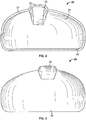
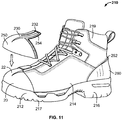
- Fig. 11 depicts footwear 210, according to another embodiment of the invention. Due to the similarities between the previous variants of footwear and footwear 210, like reference numerals refer to like elements in this embodiment (although in the 200-series of numbers), and predominantly the differences between each footwear embodiment is discussed below.
- Footwear 210 includes toe cap 20, as with each of the previous embodiments.
- Toe cap 20 is shown in detail in the exploded view of Fig. 11 .
- Housing 250 Positioned over toe cap 20, however, is a housing 250, optionally composed of a rubber material for waterproofing purposes.
- Housing 250 has a protrusion forming an air vent channel 230 that matches the shape of protrusion 22 of toe cap 20 and is sized to receive protrusion 22 of toe cap 20.
- protrusion 230 has an extension part 254 that leads to a heat egress port 232. Heat egress port 232 is clearly shown in the top view of Fig. 13 .
- heat egress port 232 may comprise an opening that is covered by a mesh or other breathable fabric to allow heat to escape port 232.
- air vent channel 230 may be open in the direction of the user's foot or it may be covered by a mesh or other breathable fabric to allow heat to enter channel 230 and exit footwear 210 via heat egress port 232.
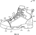
- Footwear 210 may also include a heel counter 260 that has its own heat egress port 262 for allowing heat to escape from heel region 216 of footwear 210. As shown in Figs. 12-13 , heat egress port 262 may extend circumferentially around a majority of heel region 216 of footwear 210 to provide adequate ventilation.
- Toe cap 20 of footwear 210 provides sufficient safety protection during use, along with ventilation via its channel 23, rubber housing 250 provides additional safety protection in addition to waterproofing characteristics, and heat egress port 262 of heel counter 260 allows for ventilation in heel region 216 of footwear 210.
- Such ventilation and safety structures provide for improved safety footwear 210 with efficient ventilation to keep a user's foot comfortable during use.
- footwear 210' is shown in Fig. 14 .
- Footwear 210' includes one or more side or lateral vents 258' positioned on one or both sides of air vent channel 230' of housing 250' (e.g., to provide for lateral air ventilation out of channel 230').
- Footwear 210' may also include a heat egress port 232' or it optionally may be closed and not include such a port, as shown in Fig. 14 .
- footwear 210' is the same as footwear 210, and thus, like reference numerals refer to like elements in this embodiment (although a prime designation is added to the reference numerals of Fig. 14 ).
- footwear 210' may include all of the features of footwear 210 of the previous embodiment, although not specifically discussed herein.
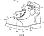
- Fig. 15 depicts footwear 310, according to yet another embodiment of the invention. Due to the similarities between the previous variants of footwear and footwear 310, like reference numerals refer to like elements in this embodiment (although in the 300-series of numbers), and predominantly the differences between each footwear embodiment are discussed below.
- Footwear 310 is different from previous embodiments in that, although toe cap 20 is used as in all embodiments, the ventilation structure of footwear 310 is incorporated into a metatarsal guard 370 component.
- a particular embodiment of a metatarsal guard 370 is shown in Fig. 16 .
- metatarsal guard 370 may include an enclosed ventilation channel 372 with an opening 374 on a forefoot side of channel 372 and one or more lateral vents 376 in channel 372.
- Lateral vents 376 may extend along one or both sides of channel 372. For instance, in the embodiment shown in Fig. 15 , lateral vents 376 extend along only a single side of channel 372, while in the embodiment of Fig. 16 lateral vents 376 extend along both sides.
- Ventilation channel 372 may also be closed at a midfoot side of channel 372, as shown in Fig. 16 .
- an inside surface 371 of metatarsal guard 370 is shaped to overlie and protect the metatarsal region of a user's foot during use ( e.g ., from injury due to a falling object).
- metatarsal guard 370 has a saddle-shaped inside surface 371 that is convex in a longitudinal direction and concave in a lateral direction.
- Metatarsal guard 370 may be incorporated into a flap or pocket 380 of footwear 310, as shown in Fig. 15 .
- Fig. 15 depicts an embodiment of metatarsal guard 370 where ventilation channel 372 has vents 376 along only one side of channel 372.
- Metatarsal guard 370 is positioned within pocket 380, and acts to provide ventilation for the foot as well as protect the metatarsal area of the foot from injury.
- footwear 310 may also have a heat egress port 332 in pocket 380 that allows for further ventilation.
- Metatarsal guard 370 may also include any of the protective features and/or patterns disclosed in Applicant's U.S. Patent No. 8,635,789 , directed to various metatarsal 2. guards.
Landscapes
- Health & Medical Sciences (AREA)
- Epidemiology (AREA)
- General Health & Medical Sciences (AREA)
- Public Health (AREA)
- Footwear And Its Accessory, Manufacturing Method And Apparatuses (AREA)
Claims (15)
- Article pour chaussure comprenant :une tige (119) définissant une cavité dimensionnée et formée pour recevoir un pied d'un utilisateur, dans lequel la tige est fixée à une semelle (117) ; etun embout protecteur (20) positionné adjacent à une région au bout de la chaussure, l'embout fonctionnant pour protéger une partie d'avant-pied du pied de l'utilisateur des blessures et présentant une forme arquée comportant une section disposée de façon à recouvrir les orteils du pied de l'utilisateur en utilisation, dans lequel l'embout comporte un côté d'avant-pied (28) et un côté de milieu de pied (27) et inclut un canal de ventilation (23) servant à fournir une ventilation dans la région des orteils, caractérisé en ce que le canal de ventilation (23) est défini dans une protubérance (22) s'étendant du côté de milieu de pied (27) au côté d'avant-pied (28), la protubérance (22) présentant une hauteur maximale sur le côté de milieu de pied (27) et diminuant dans la direction du côté d'avant-pied (28).
- Article pour chaussure selon la revendication 1, dans lequel l'embout (20) présente une forme de semi-dôme et le canal de ventilation (23) s'étend le long d'un axe longitudinal de l'embout.
- Article pour chaussure selon la revendication 1, dans lequel l'embout (20) inclut soit :des surfaces intérieure et extérieure et le canal de ventilation (23) est ouvert le long de la surface intérieure (24) de l'embout, soitde multiples canaux de ventilation.
- Article pour chaussure selon la revendication 1, dans lequel la tige (119) inclut une languette (118) et un canal de ventilation (30) est positionné le long de la languette.
- Article pour chaussure selon la revendication 4, dans lequel le canal de ventilation (30) de la languette (118) est en communication avec un port de sortie de chaleur (32) fonctionnant pour permettre à la chaleur de sortir du canal de ventilation (30).
- Article pour chaussure selon la revendication 5, dans lequel le canal de ventilation (30) de la languette (118) est soit :ouvert le long d'un premier côté du canal de ventilation faisant face au pied de l'utilisateur et fermé le long d'un second côté du canal de ventilation orienté à l'opposé du pied de l'utilisateur, soiten communication avec le port d'entrée d'air (34) positionné adjacent à une région d'avant-pied de la chaussure.
- Article pour chaussure selon la revendication 4, dans lequel le canal de ventilation (30) de la languette (118), soit :s'étend le long de la plus grande partie de la longueur de la languette, soitest aligné avec le canal de ventilation (23) de l'embout (20) pour constituer un canal de ventilation continu s'étendant d'une région d'avant-pied de la chaussure à une région de cambrure de la chaussure.
- Article pour chaussure selon la revendication 1, dans lequel un logement étanche à l'eau (250) est positionné par-dessus l'embout protecteur (20), le logement étanche à l'eau fournissant une étanchéité à l'eau dans une région d'avant-pied de la chaussure.
- Article pour chaussure selon la revendication 8, dans lequel le logement étanche à l'eau (250) inclut soit :un canal de ventilation (230) comportant un port de sortie de chaleur (232) servant à fournir une ventilation dans la région d'avant-pied, soitune aération latérale (258') le long d'un côté de son canal de ventilation (230') pour fournir une ventilation supplémentaire dans la région d'avant-pied.
- Article pour chaussure selon la revendication 1, comprenant en outre un protège-pied (370) comportant un canal de ventilation (372) s'étendant le long d'un axe longitudinal de la chaussure, dans lequel le canal de ventilation du protège-pied comporte une aération latérale (376) pour permettre à la chaleur de sortir du canal de ventilation.
- Article pour chaussure selon la revendication 10, dans lequel le canal de ventilation (372) du protège-pied (370) est défini par des premier et second côtés, et de multiples aérations latérales (376) sont formées dans le canal de ventilation le long des premier et second côtés.
- Embout protecteur (20) pour un article pour chaussure comprenant :
un corps en forme de semi-dôme dimensionné et formé pour recouvrir les orteils d'un utilisateur une fois incorporé dans la chaussure, le corps comportant des surfaces intérieure et extérieure et un canal de ventilation (23) s'étendant dans une direction longitudinale entre un côté d'avant-pied (28) et un côté de milieu de pied (27) sur le corps, le canal de ventilation (23) étant ouvert le long de la surface intérieure (24) pour permettre à l'air de se déplacer le long du canal de ventilation, caractérisé en ce que le canal de ventilation (23) est défini dans une protubérance (22) s'étendant du côté de milieu de pied (27) au côté d'avant-pied (28), la protubérance (22) présentant une hauteur maximale sur le côté de milieu de pied (27) et diminuant dans la direction du côté d'avant-pied (28). - Embout protecteur selon la revendication 12, dans lequel le canal de ventilation (23), soit :définit une ouverture sur le côté d'avant-pied (28) du corps, soitinclut une surface intérieure qui est décalée par rapport à la surface intérieure (24) du corps de l'embout, et les surfaces intérieures du canal de ventilation et de l'embout convergent dans la direction du côté d'avant-pied (28) du corps.
- Embout protecteur selon la revendication 12, dans lequel l'embout est rigide et présente des caractéristiques de résistance suffisantes pour satisfaire à la norme ASTM F2413-11.
- Embout protecteur selon la revendication 12, dans lequel l'embout inclut de multiples canaux de ventilation (23).
Applications Claiming Priority (2)
| Application Number | Priority Date | Filing Date | Title |
|---|---|---|---|
| US201562172433P | 2015-06-08 | 2015-06-08 | |
| PCT/US2016/036455 WO2016200946A1 (fr) | 2015-06-08 | 2016-06-08 | Structures et procédés de ventilation de chaussure |
Publications (3)
| Publication Number | Publication Date |
|---|---|
| EP3302131A1 EP3302131A1 (fr) | 2018-04-11 |
| EP3302131A4 EP3302131A4 (fr) | 2019-01-23 |
| EP3302131B1 true EP3302131B1 (fr) | 2020-05-27 |
Family
ID=57504630
Family Applications (1)
| Application Number | Title | Priority Date | Filing Date |
|---|---|---|---|
| EP16808192.5A Active EP3302131B1 (fr) | 2015-06-08 | 2016-06-08 | Structures et procédés de ventilation de chaussure |
Country Status (4)
| Country | Link |
|---|---|
| EP (1) | EP3302131B1 (fr) |
| CA (1) | CA2986050C (fr) |
| MX (1) | MX391506B (fr) |
| WO (1) | WO2016200946A1 (fr) |
Families Citing this family (1)
| Publication number | Priority date | Publication date | Assignee | Title |
|---|---|---|---|---|
| DE102022202833A1 (de) * | 2022-03-23 | 2023-09-28 | Uvex Arbeitsschutz Gmbh | Schutzschuh |
Family Cites Families (6)
| Publication number | Priority date | Publication date | Assignee | Title |
|---|---|---|---|---|
| US7818895B2 (en) * | 2006-05-24 | 2010-10-26 | International Truck Intellectual Property Company, Llc | Shoe for professional truckers |
| US7992325B2 (en) * | 2006-11-06 | 2011-08-09 | Shew, Inc. | Flexibly rigid personal protective equipment components |
| PT2220955E (pt) * | 2007-12-14 | 2015-10-23 | Tecnotac S L | Biqueira de segurança para calçado |
| CN201790070U (zh) * | 2010-09-30 | 2011-04-13 | 赛纳集团有限公司 | 塑料包头安全鞋 |
| US9119441B2 (en) * | 2010-12-30 | 2015-09-01 | Sport Maska Inc. | Skate boot tongue |
| DK2740379T3 (en) * | 2012-12-10 | 2015-01-05 | Arbesko Gruppen Ab | Safety toe |
-
2016
- 2016-06-08 MX MX2017016027A patent/MX391506B/es unknown
- 2016-06-08 CA CA2986050A patent/CA2986050C/fr active Active
- 2016-06-08 EP EP16808192.5A patent/EP3302131B1/fr active Active
- 2016-06-08 WO PCT/US2016/036455 patent/WO2016200946A1/fr not_active Ceased
Non-Patent Citations (1)
| Title |
|---|
| None * |
Also Published As
| Publication number | Publication date |
|---|---|
| MX2017016027A (es) | 2018-04-20 |
| MX391506B (es) | 2025-03-21 |
| EP3302131A4 (fr) | 2019-01-23 |
| CA2986050C (fr) | 2019-11-12 |
| EP3302131A1 (fr) | 2018-04-11 |
| CA2986050A1 (fr) | 2016-12-15 |
| WO2016200946A1 (fr) | 2016-12-15 |
Similar Documents
| Publication | Publication Date | Title |
|---|---|---|
| US10743622B2 (en) | Footwear ventilation structures and methods | |
| US7762008B1 (en) | Extreme service footwear | |
| US20070214682A1 (en) | Ventilated shoe sole construction with improved medical support | |
| US8359769B2 (en) | Chimney structures for footwear | |
| US5546680A (en) | Safety footwear | |
| US20060277785A1 (en) | Chimney structures for footwear and foot coverings | |
| US20160157554A1 (en) | Air exhaust outsole for safety footwear | |
| US20060277786A1 (en) | Chimney structures for apparel | |
| US20030136023A1 (en) | Shoe with drainable ports | |
| WO2020146641A1 (fr) | Systèmes et procédés pour améliorer le confort et le style de bottes | |
| EP3302131B1 (fr) | Structures et procédés de ventilation de chaussure | |
| KR101530816B1 (ko) | 교체형 개폐구를 갖는 통풍 신발 | |
| WO2017029356A1 (fr) | Botte d'équitation | |
| US20150320140A1 (en) | Sandal having grooves for drainage | |
| KR100564792B1 (ko) | 바닥면과 외주연부에 통풍구가 구비된 신발밑창 | |
| WO2020044356A1 (fr) | Chaussure guidée par un écoulement d'air pour travailler dans un champ boueux | |
| US10925345B2 (en) | Footwear with zoned insulation | |
| KR200487679Y1 (ko) | 통기가 가능한 신발 | |
| JP7004705B2 (ja) | 通気性を改善した二重構造の組立式シューズ | |
| EP1728444B1 (fr) | Structure de cheminée pour chaussure et chausson pour pied | |
| EP3662778A1 (fr) | Chaussures à conception respirante | |
| KR102586181B1 (ko) | 에어메쉬띠가 형성된 통풍 신발 | |
| US20240306763A1 (en) | Split-toe shoe | |
| RU209401U1 (ru) | Защитная стелька | |
| KR20230000764U (ko) | 발등보호기능, 통기성 및 착용감이 향상된 eva 사출 신발 |
Legal Events
| Date | Code | Title | Description |
|---|---|---|---|
| STAA | Information on the status of an ep patent application or granted ep patent |
Free format text: STATUS: THE INTERNATIONAL PUBLICATION HAS BEEN MADE |
|
| PUAI | Public reference made under article 153(3) epc to a published international application that has entered the european phase |
Free format text: ORIGINAL CODE: 0009012 |
|
| STAA | Information on the status of an ep patent application or granted ep patent |
Free format text: STATUS: REQUEST FOR EXAMINATION WAS MADE |
|
| 17P | Request for examination filed |
Effective date: 20180108 |
|
| AK | Designated contracting states |
Kind code of ref document: A1 Designated state(s): AL AT BE BG CH CY CZ DE DK EE ES FI FR GB GR HR HU IE IS IT LI LT LU LV MC MK MT NL NO PL PT RO RS SE SI SK SM TR |
|
| AX | Request for extension of the european patent |
Extension state: BA ME |
|
| DAV | Request for validation of the european patent (deleted) | ||
| DAX | Request for extension of the european patent (deleted) | ||
| A4 | Supplementary search report drawn up and despatched |
Effective date: 20181221 |
|
| RIC1 | Information provided on ipc code assigned before grant |
Ipc: A43B 7/00 20060101ALI20181217BHEP Ipc: A43B 7/10 20060101ALI20181217BHEP Ipc: A43B 7/08 20060101AFI20181217BHEP |
|
| GRAP | Despatch of communication of intention to grant a patent |
Free format text: ORIGINAL CODE: EPIDOSNIGR1 |
|
| STAA | Information on the status of an ep patent application or granted ep patent |
Free format text: STATUS: GRANT OF PATENT IS INTENDED |
|
| INTG | Intention to grant announced |
Effective date: 20191212 |
|
| GRAS | Grant fee paid |
Free format text: ORIGINAL CODE: EPIDOSNIGR3 |
|
| GRAA | (expected) grant |
Free format text: ORIGINAL CODE: 0009210 |
|
| STAA | Information on the status of an ep patent application or granted ep patent |
Free format text: STATUS: THE PATENT HAS BEEN GRANTED |
|
| AK | Designated contracting states |
Kind code of ref document: B1 Designated state(s): AL AT BE BG CH CY CZ DE DK EE ES FI FR GB GR HR HU IE IS IT LI LT LU LV MC MK MT NL NO PL PT RO RS SE SI SK SM TR |
|
| REG | Reference to a national code |
Ref country code: GB Ref legal event code: FG4D |
|
| REG | Reference to a national code |
Ref country code: CH Ref legal event code: EP |
|
| REG | Reference to a national code |
Ref country code: DE Ref legal event code: R096 Ref document number: 602016037167 Country of ref document: DE |
|
| REG | Reference to a national code |
Ref country code: AT Ref legal event code: REF Ref document number: 1273590 Country of ref document: AT Kind code of ref document: T Effective date: 20200615 |
|
| REG | Reference to a national code |
Ref country code: LT Ref legal event code: MG4D |
|
| PG25 | Lapsed in a contracting state [announced via postgrant information from national office to epo] |
Ref country code: IS Free format text: LAPSE BECAUSE OF FAILURE TO SUBMIT A TRANSLATION OF THE DESCRIPTION OR TO PAY THE FEE WITHIN THE PRESCRIBED TIME-LIMIT Effective date: 20200927 Ref country code: FI Free format text: LAPSE BECAUSE OF FAILURE TO SUBMIT A TRANSLATION OF THE DESCRIPTION OR TO PAY THE FEE WITHIN THE PRESCRIBED TIME-LIMIT Effective date: 20200527 Ref country code: PT Free format text: LAPSE BECAUSE OF FAILURE TO SUBMIT A TRANSLATION OF THE DESCRIPTION OR TO PAY THE FEE WITHIN THE PRESCRIBED TIME-LIMIT Effective date: 20200928 Ref country code: LT Free format text: LAPSE BECAUSE OF FAILURE TO SUBMIT A TRANSLATION OF THE DESCRIPTION OR TO PAY THE FEE WITHIN THE PRESCRIBED TIME-LIMIT Effective date: 20200527 Ref country code: NO Free format text: LAPSE BECAUSE OF FAILURE TO SUBMIT A TRANSLATION OF THE DESCRIPTION OR TO PAY THE FEE WITHIN THE PRESCRIBED TIME-LIMIT Effective date: 20200827 Ref country code: SE Free format text: LAPSE BECAUSE OF FAILURE TO SUBMIT A TRANSLATION OF THE DESCRIPTION OR TO PAY THE FEE WITHIN THE PRESCRIBED TIME-LIMIT Effective date: 20200527 Ref country code: GR Free format text: LAPSE BECAUSE OF FAILURE TO SUBMIT A TRANSLATION OF THE DESCRIPTION OR TO PAY THE FEE WITHIN THE PRESCRIBED TIME-LIMIT Effective date: 20200828 |
|
| REG | Reference to a national code |
Ref country code: NL Ref legal event code: MP Effective date: 20200527 |
|
| PG25 | Lapsed in a contracting state [announced via postgrant information from national office to epo] |
Ref country code: BG Free format text: LAPSE BECAUSE OF FAILURE TO SUBMIT A TRANSLATION OF THE DESCRIPTION OR TO PAY THE FEE WITHIN THE PRESCRIBED TIME-LIMIT Effective date: 20200827 Ref country code: HR Free format text: LAPSE BECAUSE OF FAILURE TO SUBMIT A TRANSLATION OF THE DESCRIPTION OR TO PAY THE FEE WITHIN THE PRESCRIBED TIME-LIMIT Effective date: 20200527 Ref country code: RS Free format text: LAPSE BECAUSE OF FAILURE TO SUBMIT A TRANSLATION OF THE DESCRIPTION OR TO PAY THE FEE WITHIN THE PRESCRIBED TIME-LIMIT Effective date: 20200527 Ref country code: LV Free format text: LAPSE BECAUSE OF FAILURE TO SUBMIT A TRANSLATION OF THE DESCRIPTION OR TO PAY THE FEE WITHIN THE PRESCRIBED TIME-LIMIT Effective date: 20200527 |
|
| REG | Reference to a national code |
Ref country code: AT Ref legal event code: MK05 Ref document number: 1273590 Country of ref document: AT Kind code of ref document: T Effective date: 20200527 |
|
| PG25 | Lapsed in a contracting state [announced via postgrant information from national office to epo] |
Ref country code: NL Free format text: LAPSE BECAUSE OF FAILURE TO SUBMIT A TRANSLATION OF THE DESCRIPTION OR TO PAY THE FEE WITHIN THE PRESCRIBED TIME-LIMIT Effective date: 20200527 Ref country code: AL Free format text: LAPSE BECAUSE OF FAILURE TO SUBMIT A TRANSLATION OF THE DESCRIPTION OR TO PAY THE FEE WITHIN THE PRESCRIBED TIME-LIMIT Effective date: 20200527 |
|
| PG25 | Lapsed in a contracting state [announced via postgrant information from national office to epo] |
Ref country code: EE Free format text: LAPSE BECAUSE OF FAILURE TO SUBMIT A TRANSLATION OF THE DESCRIPTION OR TO PAY THE FEE WITHIN THE PRESCRIBED TIME-LIMIT Effective date: 20200527 Ref country code: SM Free format text: LAPSE BECAUSE OF FAILURE TO SUBMIT A TRANSLATION OF THE DESCRIPTION OR TO PAY THE FEE WITHIN THE PRESCRIBED TIME-LIMIT Effective date: 20200527 Ref country code: DK Free format text: LAPSE BECAUSE OF FAILURE TO SUBMIT A TRANSLATION OF THE DESCRIPTION OR TO PAY THE FEE WITHIN THE PRESCRIBED TIME-LIMIT Effective date: 20200527 Ref country code: RO Free format text: LAPSE BECAUSE OF FAILURE TO SUBMIT A TRANSLATION OF THE DESCRIPTION OR TO PAY THE FEE WITHIN THE PRESCRIBED TIME-LIMIT Effective date: 20200527 Ref country code: AT Free format text: LAPSE BECAUSE OF FAILURE TO SUBMIT A TRANSLATION OF THE DESCRIPTION OR TO PAY THE FEE WITHIN THE PRESCRIBED TIME-LIMIT Effective date: 20200527 Ref country code: CZ Free format text: LAPSE BECAUSE OF FAILURE TO SUBMIT A TRANSLATION OF THE DESCRIPTION OR TO PAY THE FEE WITHIN THE PRESCRIBED TIME-LIMIT Effective date: 20200527 Ref country code: ES Free format text: LAPSE BECAUSE OF FAILURE TO SUBMIT A TRANSLATION OF THE DESCRIPTION OR TO PAY THE FEE WITHIN THE PRESCRIBED TIME-LIMIT Effective date: 20200527 |
|
| REG | Reference to a national code |
Ref country code: CH Ref legal event code: PL |
|
| PG25 | Lapsed in a contracting state [announced via postgrant information from national office to epo] |
Ref country code: PL Free format text: LAPSE BECAUSE OF FAILURE TO SUBMIT A TRANSLATION OF THE DESCRIPTION OR TO PAY THE FEE WITHIN THE PRESCRIBED TIME-LIMIT Effective date: 20200527 Ref country code: MC Free format text: LAPSE BECAUSE OF FAILURE TO SUBMIT A TRANSLATION OF THE DESCRIPTION OR TO PAY THE FEE WITHIN THE PRESCRIBED TIME-LIMIT Effective date: 20200527 Ref country code: SK Free format text: LAPSE BECAUSE OF FAILURE TO SUBMIT A TRANSLATION OF THE DESCRIPTION OR TO PAY THE FEE WITHIN THE PRESCRIBED TIME-LIMIT Effective date: 20200527 |
|
| REG | Reference to a national code |
Ref country code: DE Ref legal event code: R097 Ref document number: 602016037167 Country of ref document: DE |
|
| PG25 | Lapsed in a contracting state [announced via postgrant information from national office to epo] |
Ref country code: LU Free format text: LAPSE BECAUSE OF NON-PAYMENT OF DUE FEES Effective date: 20200608 |
|
| PLBE | No opposition filed within time limit |
Free format text: ORIGINAL CODE: 0009261 |
|
| STAA | Information on the status of an ep patent application or granted ep patent |
Free format text: STATUS: NO OPPOSITION FILED WITHIN TIME LIMIT |
|
| REG | Reference to a national code |
Ref country code: BE Ref legal event code: MM Effective date: 20200630 |
|
| PG25 | Lapsed in a contracting state [announced via postgrant information from national office to epo] |
Ref country code: LI Free format text: LAPSE BECAUSE OF NON-PAYMENT OF DUE FEES Effective date: 20200630 Ref country code: CH Free format text: LAPSE BECAUSE OF NON-PAYMENT OF DUE FEES Effective date: 20200630 Ref country code: IE Free format text: LAPSE BECAUSE OF NON-PAYMENT OF DUE FEES Effective date: 20200608 |
|
| 26N | No opposition filed |
Effective date: 20210302 |
|
| PG25 | Lapsed in a contracting state [announced via postgrant information from national office to epo] |
Ref country code: BE Free format text: LAPSE BECAUSE OF NON-PAYMENT OF DUE FEES Effective date: 20200630 Ref country code: SI Free format text: LAPSE BECAUSE OF FAILURE TO SUBMIT A TRANSLATION OF THE DESCRIPTION OR TO PAY THE FEE WITHIN THE PRESCRIBED TIME-LIMIT Effective date: 20200527 |
|
| PG25 | Lapsed in a contracting state [announced via postgrant information from national office to epo] |
Ref country code: TR Free format text: LAPSE BECAUSE OF FAILURE TO SUBMIT A TRANSLATION OF THE DESCRIPTION OR TO PAY THE FEE WITHIN THE PRESCRIBED TIME-LIMIT Effective date: 20200527 Ref country code: MT Free format text: LAPSE BECAUSE OF FAILURE TO SUBMIT A TRANSLATION OF THE DESCRIPTION OR TO PAY THE FEE WITHIN THE PRESCRIBED TIME-LIMIT Effective date: 20200527 Ref country code: CY Free format text: LAPSE BECAUSE OF FAILURE TO SUBMIT A TRANSLATION OF THE DESCRIPTION OR TO PAY THE FEE WITHIN THE PRESCRIBED TIME-LIMIT Effective date: 20200527 |
|
| PG25 | Lapsed in a contracting state [announced via postgrant information from national office to epo] |
Ref country code: MK Free format text: LAPSE BECAUSE OF FAILURE TO SUBMIT A TRANSLATION OF THE DESCRIPTION OR TO PAY THE FEE WITHIN THE PRESCRIBED TIME-LIMIT Effective date: 20200527 |
|
| PGFP | Annual fee paid to national office [announced via postgrant information from national office to epo] |
Ref country code: DE Payment date: 20250627 Year of fee payment: 10 |
|
| PGFP | Annual fee paid to national office [announced via postgrant information from national office to epo] |
Ref country code: GB Payment date: 20250627 Year of fee payment: 10 |
|
| PGFP | Annual fee paid to national office [announced via postgrant information from national office to epo] |
Ref country code: FR Payment date: 20250625 Year of fee payment: 10 |
|
| PGFP | Annual fee paid to national office [announced via postgrant information from national office to epo] |
Ref country code: IT Payment date: 20250619 Year of fee payment: 10 |