EP3302197B1 - Mélangeur avec un joint d'étanchéité comportant des nervures - Google Patents
Mélangeur avec un joint d'étanchéité comportant des nervures Download PDFInfo
- Publication number
- EP3302197B1 EP3302197B1 EP16724055.5A EP16724055A EP3302197B1 EP 3302197 B1 EP3302197 B1 EP 3302197B1 EP 16724055 A EP16724055 A EP 16724055A EP 3302197 B1 EP3302197 B1 EP 3302197B1
- Authority
- EP
- European Patent Office
- Prior art keywords
- blender
- rib
- container
- sealing gasket
- bottom part
- Prior art date
- Legal status (The legal status is an assumption and is not a legal conclusion. Google has not performed a legal analysis and makes no representation as to the accuracy of the status listed.)
- Active
Links
Images




Classifications
-
- A—HUMAN NECESSITIES
- A47—FURNITURE; DOMESTIC ARTICLES OR APPLIANCES; COFFEE MILLS; SPICE MILLS; SUCTION CLEANERS IN GENERAL
- A47J—KITCHEN EQUIPMENT; COFFEE MILLS; SPICE MILLS; APPARATUS FOR MAKING BEVERAGES
- A47J43/00—Implements for preparing or holding food, not provided for in other groups of this subclass
- A47J43/04—Machines for domestic use not covered elsewhere, e.g. for grinding, mixing, stirring, kneading, emulsifying, whipping or beating foodstuffs, e.g. power-driven
- A47J43/07—Parts or details, e.g. mixing tools, whipping tools
- A47J43/0716—Parts or details, e.g. mixing tools, whipping tools for machines with tools driven from the lower side
-
- A—HUMAN NECESSITIES
- A47—FURNITURE; DOMESTIC ARTICLES OR APPLIANCES; COFFEE MILLS; SPICE MILLS; SUCTION CLEANERS IN GENERAL
- A47J—KITCHEN EQUIPMENT; COFFEE MILLS; SPICE MILLS; APPARATUS FOR MAKING BEVERAGES
- A47J43/00—Implements for preparing or holding food, not provided for in other groups of this subclass
- A47J43/04—Machines for domestic use not covered elsewhere, e.g. for grinding, mixing, stirring, kneading, emulsifying, whipping or beating foodstuffs, e.g. power-driven
- A47J43/046—Machines for domestic use not covered elsewhere, e.g. for grinding, mixing, stirring, kneading, emulsifying, whipping or beating foodstuffs, e.g. power-driven with tools driven from the bottom side
-
- A—HUMAN NECESSITIES
- A47—FURNITURE; DOMESTIC ARTICLES OR APPLIANCES; COFFEE MILLS; SPICE MILLS; SUCTION CLEANERS IN GENERAL
- A47J—KITCHEN EQUIPMENT; COFFEE MILLS; SPICE MILLS; APPARATUS FOR MAKING BEVERAGES
- A47J43/00—Implements for preparing or holding food, not provided for in other groups of this subclass
- A47J43/04—Machines for domestic use not covered elsewhere, e.g. for grinding, mixing, stirring, kneading, emulsifying, whipping or beating foodstuffs, e.g. power-driven
- A47J43/07—Parts or details, e.g. mixing tools, whipping tools
- A47J43/0716—Parts or details, e.g. mixing tools, whipping tools for machines with tools driven from the lower side
- A47J43/0722—Mixing, whipping or cutting tools
-
- A—HUMAN NECESSITIES
- A47—FURNITURE; DOMESTIC ARTICLES OR APPLIANCES; COFFEE MILLS; SPICE MILLS; SUCTION CLEANERS IN GENERAL
- A47J—KITCHEN EQUIPMENT; COFFEE MILLS; SPICE MILLS; APPARATUS FOR MAKING BEVERAGES
- A47J43/00—Implements for preparing or holding food, not provided for in other groups of this subclass
- A47J43/04—Machines for domestic use not covered elsewhere, e.g. for grinding, mixing, stirring, kneading, emulsifying, whipping or beating foodstuffs, e.g. power-driven
- A47J43/07—Parts or details, e.g. mixing tools, whipping tools
- A47J43/0727—Mixing bowls
-
- F—MECHANICAL ENGINEERING; LIGHTING; HEATING; WEAPONS; BLASTING
- F16—ENGINEERING ELEMENTS AND UNITS; GENERAL MEASURES FOR PRODUCING AND MAINTAINING EFFECTIVE FUNCTIONING OF MACHINES OR INSTALLATIONS; THERMAL INSULATION IN GENERAL
- F16J—PISTONS; CYLINDERS; SEALINGS
- F16J15/00—Sealings
- F16J15/16—Sealings between relatively-moving surfaces
- F16J15/32—Sealings between relatively-moving surfaces with elastic sealings, e.g. O-rings
- F16J15/3204—Sealings between relatively-moving surfaces with elastic sealings, e.g. O-rings with at least one lip
- F16J15/3232—Sealings between relatively-moving surfaces with elastic sealings, e.g. O-rings with at least one lip having two or more lips
-
- B—PERFORMING OPERATIONS; TRANSPORTING
- B01—PHYSICAL OR CHEMICAL PROCESSES OR APPARATUS IN GENERAL
- B01F—MIXING, e.g. DISSOLVING, EMULSIFYING OR DISPERSING
- B01F35/00—Accessories for mixers; Auxiliary operations or auxiliary devices; Parts or details of general application
- B01F35/30—Driving arrangements; Transmissions; Couplings; Brakes
- B01F2035/35—Use of other general mechanical engineering elements in mixing devices
- B01F2035/351—Sealings
Definitions
- the invention relates to a blender with a sealing gasket comprising ribs.
- the invention may be used in the field of food blending, in particular kitchen appliance blenders.
- Blenders are kitchen appliances which are designed for mixing or blending food ingredients such as fruit, milk and ice, into liquids.
- Blenders typically consist of a base, having a vertically positioned powerful a/c motor with a lower coupling, and a cylindrical jar located directly above the base.
- the jar has a rotatable blade assembly at the bottom with an upper coupling driven by the lower coupling.
- the blade assembly is usually mounted in a blade-holding component which forms the bottom of the jar with a water tight seal in between, and removable for easy cleaning.
- the blending performance of a blender is usually measured by the fineness of blended food ingredients after a limited time of blending.
- Critical for good performance of a blender is the diameter of the jar at blade height, but also the presence of turbulence-creating ribs of similar formations inside the jar, for example at blade assembly height. Such rib formations reduce spinning of liquid inside the jar, which thus enhances blending performance.
- blenders usually have jar made of glass material.
- FIG.1 An example of a known blender 100 is depicted in Fig.1 . It comprises a base part 101 and a jar 102 made of glass arranged on the base part 101. The bottom part of the jar 102 is closed by a detachable bottom part 103. A sealing gasket 104 is disposed between the detachable bottom part 103 and the jar 102.
- the jar 102 comprises ribs 105 extending upwards on the inside surface of the jar 102. The ribs 105 are made of glass and are moulded together with the wall of the jar 102.
- a blade assembly 106 is disposed on the bottom part 103 and rotated by a motor assembly 107 disposed in the base part 101.
- the geometry is cylindrical and uniform, without large protruding ribs inside the jar. This creates a dilemma since the very same ribs are critical to obtain good blending performance.
- the width of the ribs can be reduced to facilitate the moulding during manufacturing, but to the detriment of blending performance.
- US 3344829A discloses a gasket arrangement for blender containers which have removable bases. Such arrangement can prevent food particles from becoming trapped when the blender container is washed by simply rinsing and will function effectively whether the removable container base in used with a specially designed blender container or with a standard Mason jar. However, it cannot totally solve the above mentioned problems existed in the prior arts.
- the blender according to the invention comprises:
- the jar By having the ribs directly part of the sealing gasket, the jar can be made of glass without any ribs on the inside surface of the jar. The manufacturing of the glass jar is thus facilitated because the inside surface of the jar does not have protuberances. This also contributes to an easier cleaning of the inside jar by a user. Moreover, high blending performance of the blender is ensured by having some ribs still extending inside the jar. Since the sealing gasket is a removable part of the blender, this also contributes to an easier cleaning of the ribs by a user. Having a plurality of ribs improves the blending performance.
- the more than one rib extends along an internal surface of a lower portion of the container.
- the tab portion is arranged at an upper part of the more than one rib.
- Having the tab portion disposed at this position helps to retain the food ingredients in a lower part of the jar. This helps limit that the food ingredients splash upwards inside/outside the jar during blending, and also further improves the blending performance.
- the tab portion forms a truncated pyramid.
- This shape allows creating optimum turbulences of the food ingredients during blending.
- the sealing gasket comprises a ring element having a first surface facing the detachable bottom part and a second surface facing the container, wherein at least one of the first surface and the second surface comprises concentric compression ribs.
- the concentric compression ribs arranged on the ring element further improve the sealing between the detachable bottom part and the container.
- the sealing gasket and the more than one rib form a single element made of moulded rubber material.
- the more than one rib has a height in the range [10 mm; 50 mm].
- This range of value contributes to obtaining optimal blending performance for kitchen appliance blenders.
- the more than one rib has a thickness in the range [3 mm; 15 mm].
- This range of value contributes to obtaining optimal blending performance for kitchen appliance blenders.
- the more than one rib has a width in the range [10 mm; 30 mm].
- This range of value contributes to obtaining optimal blending performance for kitchen appliance blenders.
- the blender further comprises a blade assembly comprising a plurality of blades and arranged on the bottom part and extending inside the container, and a gearing system to rotate the blade assembly.
- the more than one rib extends upwards inside the container up to a height where the plurality of blades connect, with a variation within a range of [-20%; +100%].
- the blender further comprises a locking element to press the container, the sealing gasket and the detachable bottom part against each other.
- the base part further comprises a heating element to transfer heat by conduction to the detachable bottom part.
- the heating element allows cooking the food ingredients being inside the jar, for example after blending, while having the possibility to easily detach the jar from the base after cooking.
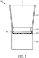
- Fig.2 depicts a blender 200 according to the invention.
- the blender 200 comprises a base part 201.
- the base part 201 is intended to receive the gearing system (not shown) to rotate a blade assembly (not shown) used to blend food ingredients.
- the blender 200 also comprises a container 202 arranged on the base part 201.
- the container 202 corresponds to the jar in which food ingredients to be blended are put.
- the container 202 comprises a detachable bottom part 203.
- the detachable bottom part 203 is intended to close the bottom part of the container 202.
- the blender 200 also comprises a sealing gasket 204 arranged between the detachable bottom part 203 and the container 202.
- One function of the sealing gasket 204 is to ensure the sealing between the detachable bottom part 203 and the container 202 to prevent food ingredients and liquid in the container 202 from leaking outside the container 202.
- the sealing gasket 204 also comprises more than one rib 205 extending upwards inside the container 202.
- the rib(s) 205 aims to create turbulences among the food ingredients during blending, to improve the blending performance.
- the more than one rib 205 replaces the ribs made of glass and moulded together with the jar of the known blenders.
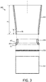
- Fig.3 depicts an exploded view of a blender 200 according to the invention
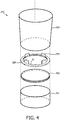
- Fig.4 depicts a corresponding three-dimensional exploded view.
- Those figures illustrate the same elements as in Fig.1 .
- the cross-section of the blender 200 is preferably circular.
- the more than one rib 205 extends along an internal surface IS of a lower portion L of the container 202.
- the lower portion L corresponds to the bottom part of the container 202 covering between 5% and 20% of the height H1 of the container 202.
- the more than one rib 205 comprises a plurality of ribs distributed around an inner periphery IP of the sealing gasket 204.
- a number of four ribs 205 is chosen.
- the ribs are regularly distributed around the inner periphery IP.
- the ribs are distributed every 90 degrees around the inner periphery IP.
- Fig.5A, Fig.5B, Fig.5C, Fig.5D depict various embodiments of a sealing gasket according to the invention comprising a tab portion 207.
- At least one of the more than one rib 205 comprises a tab portion 207 extending along a direction RD being radial compared to an inner periphery IP of the sealing gasket 204.
- the direction RD directs toward the center of the periphery IP.
- the tab portion 207 is arranged at an upper part U of the at least one of the more than one rib 205.
- the tab portion 207 is at the most upper part of the rib 205.
- the tab portion 207 is slightly below the most upper part of the rib 205.
- the tab portion 207 takes the form of a cubic element.
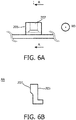
- the tab portion 207 takes the form of a truncated pyramid.
- Fig.6A depicts a zoomed-in front view of a tab portion 207 taking the form of a truncated pyramid as depicted by Fig.5D
- Fig.6B depicts the corresponding zoomed-in lateral cross-section view.
- Fig.7 depicts a three-dimensional zoomed-in view of a sealing gasket 204 according to the invention.
- the sealing gasket 204 comprises four ribs 205.
- more than one rib 205 has a height h1 in the range [10 mm; 50 mm].
- more than one rib 205 has a thickness e1 in the range [3 mm; 15 mm].
- more than one rib 205 has a width w1 in the range [10 mm; 30 mm].
- Those ranges of values are suitable for domestic appliances with a sealing gasket 204 having an external diameter with dimension between 100 mm and 150 mm.
- the sealing gasket 204 comprises a ring element 206 having a first surface S1 facing the detachable bottom part 203 and a second surface S2 facing the container 202.
- a ring element 206 having a first surface S1 facing the detachable bottom part 203 and a second surface S2 facing the container 202.
- at least one of the first surface S1 and the second surface S2 comprises concentric compression ribs CR1, CR2.
- the compression ribs CR1 are on the first surface S1.
- the compression ribs CR1 aims to further improving the contact with the bottom part 203.
- the compression ribs CR2 are on the second surface S2.
- the compression ribs CR2 aims to further improving the contact with the container 202.
- a corresponding three-dimensional view is depicted in Fig.8C .
- the compression ribs CR1 are on the first surface S1, and the compression ribs CR2 are on the second surface S2.
- the compression ribs CR1 aims to further improving the contact with the bottom part 203.
- the compression ribs CR2 aims to further improving the contact with the container 202.
- the sealing gasket 204 and the more than one rib 205 form a single element made of moulded rubber material.
- the more than one rib 205 are glued or attached as separate elements, and are for example made of plastic material.
- the sealing gasket 204 further comprises a first outer rib OR1 at an outer periphery OP of the sealing gasket 204.
- the first outer rib OR1 extends along a first vertical direction VD1 towards the detachable bottom part 203.
- the circumference of the first outer rib OR1 is such that it surrounds the detachable bottom part 203.
- the first outer rib OR1 facilitates centering the bottom part 203 on the sealing gasket 204.
- the sealing gasket 204 further comprises a second outer rib OR2 at an outer periphery OP of the sealing gasket 204.
- the second outer rib OR2 extends along a second vertical direction VD2 towards the container 202.
- the circumference of the second outer rib OR2 is such that it surrounds a lower part of the container 202.
- the second outer rib OR2 facilitates centering the container 202 on the sealing gasket 204.
- the sealing gasket 204 comprises both first outer rib OR1 and second outer rib OR2.
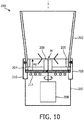
- the blender 200 further comprises a blade assembly 209 comprising a plurality of blades and arranged on the bottom part 203 and extending inside the container 202.
- the blender also comprises a gearing system 208 to rotate the blade assembly 209.
- More than one rib 205 extends upwards inside the container 202 up to a height H2 where the plurality of blades connect, with a variation within a range of [-20%; +100%]. For example, if the height H2 is 50 mm, calculated from the bottom part 203, the more than one rib 205 extends inside the container 202 up to a height H2 to any value in the range [40 mm; 100 mm].
- the blender 200 further comprises a locking element 210 to press the container 202, the sealing gasket 204 and the detachable bottom part 203 against each other.
- the locking element 210 is a bayonet mechanism with male/female parts arranged on the container 202 and the base 201.
- the base part 201 further comprises a heating element 211 to transfer heat by conduction to the detachable bottom part 203.
Landscapes
- Engineering & Computer Science (AREA)
- Mechanical Engineering (AREA)
- Food Science & Technology (AREA)
- General Engineering & Computer Science (AREA)
- Food-Manufacturing Devices (AREA)
Claims (13)
- Mixeur (200) comprenant :une partie de base (201),un récipient (202) disposé sur ladite partie de base (201), ledit récipient (202) comprenant une partie de fond amovible (203),un joint d'étanchéité (204) agencé entre ladite partie de fond amovible (203) et ledit récipient (202), caractérisé en ce que ledit joint d'étanchéité (204) comprend plusieurs nervures (205) s'étendant vers le haut depuis ladite partie de fond amovible (203) à l'intérieur dudit récipient (202), dans lequel lesdites plusieurs nervures (205) comprennent une pluralité de nervures réparties autour d'une périphérie interne (IP) dudit joint d'étanchéité (204).
- Mixeur (200) selon la revendication 1, dans lequel lesdites plusieurs nervures (205) s'étendent le long d'une surface interne (IS) d'une partie inférieure (L) dudit récipient (202).
- Mixeur (200) selon la revendication 2, dans lequel au moins l'une desdites plusieurs nervures (205) comprend une partie de patte (207) s'étendant le long d'une direction (RD) radiale par rapport à ladite périphérie interne (IP) dudit joint d'étanchéité (204).
- Mixeur (200) selon la revendication 3, dans lequel ladite partie de patte (207) est agencée au niveau d'une partie supérieure (U) de ladite au moins une desdites plusieurs nervures (205).
- Mixeur (200) selon la revendication 3, dans lequel ladite partie de patte (207) prend la forme d'une pyramide tronquée.
- Mixeur (200) selon l'une quelconque des revendications précédentes, dans lequel ledit joint d'étanchéité (204) comprend un élément annulaire (206) ayant une première surface (S1) faisant face à ladite partie de fond amovible (203) et une seconde surface (S2) faisant face audit récipient (202), dans lequel au moins une de ladite première surface (S1) et de ladite seconde surface (S2) comprend des nervures de compression concentriques (CR1, CR2).
- Mixeur (200) selon l'une quelconque des revendications précédentes, dans lequel ledit joint d'étanchéité (204) et lesdites plusieurs nervures (205) forment un élément unique constitué d'un matériau de caoutchouc moulé.
- Mixeur (200) selon l'une quelconque des revendications précédentes, dans lequel lesdites plusieurs nervures (205) ont une hauteur (h1) dans la plage [10 mm ; 50 mm].
- Mixeur (200) selon l'une quelconque des revendications précédentes, dans lequel lesdites plusieurs nervures (205) ont une épaisseur (e1) dans la plage [3 mm ; 15 mm].
- Mixeur (200) selon l'une quelconque des revendications précédentes, dans lequel lesdites plusieurs nervures (205) ont une largeur (w1) dans la plage [10 mm ; 30 mm].
- Mixeur (200) selon l'une quelconque des revendications précédentes, comprenant en outre un ensemble de lames (209) comprenant une pluralité de lames et agencé sur ladite partie de fond (203) et s'étendant à l'intérieur dudit conteneur (202), et un système de transmission (208) destiné à faire tourner ledit ensemble de lames (209), dans lequel lesdites plusieurs nervures (205) s'étendent vers le haut à l'intérieur dudit conteneur (202) jusqu'à une hauteur (H2) où ladite pluralité de lames se raccordent, avec une variation dans une plage de [-20 % ; +100 %].
- Mixeur (200) selon l'une quelconque des revendications précédentes, comprenant en outre un élément de verrouillage (210) destiné à presser ledit récipient (202), ledit joint d'étanchéité (204) et ladite partie de fond amovible (203) les uns contre les autres.
- Mixeur (200) selon l'une quelconque des revendications précédentes, dans lequel ladite partie de base (201) comprend en outre un élément chauffant (211) pour transférer de la chaleur par conduction à ladite partie de fond amovible (203).
Applications Claiming Priority (3)
| Application Number | Priority Date | Filing Date | Title |
|---|---|---|---|
| CN2015080320 | 2015-05-29 | ||
| EP15179622 | 2015-08-04 | ||
| PCT/EP2016/061513 WO2016193029A1 (fr) | 2015-05-29 | 2016-05-23 | Mélangeur avec joint d'étanchéité comportant des nervures |
Publications (2)
| Publication Number | Publication Date |
|---|---|
| EP3302197A1 EP3302197A1 (fr) | 2018-04-11 |
| EP3302197B1 true EP3302197B1 (fr) | 2018-11-14 |
Family
ID=56026887
Family Applications (1)
| Application Number | Title | Priority Date | Filing Date |
|---|---|---|---|
| EP16724055.5A Active EP3302197B1 (fr) | 2015-05-29 | 2016-05-23 | Mélangeur avec un joint d'étanchéité comportant des nervures |
Country Status (7)
| Country | Link |
|---|---|
| US (1) | US10264923B2 (fr) |
| EP (1) | EP3302197B1 (fr) |
| JP (1) | JP6419358B2 (fr) |
| KR (1) | KR101888387B1 (fr) |
| CN (1) | CN107735004B (fr) |
| RU (1) | RU2656203C1 (fr) |
| WO (1) | WO2016193029A1 (fr) |
Families Citing this family (4)
| Publication number | Priority date | Publication date | Assignee | Title |
|---|---|---|---|---|
| CA3001833A1 (fr) * | 2015-10-13 | 2017-04-20 | City Of Hope | Recepteurs d'antigenes chimeriques contenant un domaine chlorotoxine |
| CN209499488U (zh) * | 2018-10-30 | 2019-10-18 | 浙江欧焙佳厨具有限公司 | 一种奶泡机 |
| USD890821S1 (en) * | 2019-01-17 | 2020-07-21 | B9Creations, LLC | Device for cleaning an additive manufactured component |
| WO2021045802A1 (fr) | 2019-09-06 | 2021-03-11 | Beast Health, LLC | Appareil mélangeur comportant un système de verrouillage de sécurité |
Family Cites Families (25)
| Publication number | Priority date | Publication date | Assignee | Title |
|---|---|---|---|---|
| US3344829A (en) * | 1965-10-22 | 1967-10-03 | Hoover Co | Gasket arrangement for blender containers |
| US3596692A (en) * | 1969-08-14 | 1971-08-03 | Dynamics Corp America | Easy-off coupling |
| DE1941675B2 (de) | 1969-08-16 | 1971-12-23 | Kupfer Asbest Co Gustav Bach, 7100 Heilbronn | Dichtmanschette fuer eine radial wellendichtring |
| JPS5118383Y2 (fr) | 1972-01-31 | 1976-05-17 | ||
| JPS4942189U (fr) * | 1972-07-21 | 1974-04-13 | ||
| JPS577404Y2 (fr) | 1977-11-18 | 1982-02-12 | ||
| JPS54107572A (en) | 1978-02-08 | 1979-08-23 | Hitachi Ltd | Overall kneader |
| JPH0723870A (ja) | 1993-07-15 | 1995-01-27 | Matsushita Electric Ind Co Ltd | 回転調理器 |
| CN1259881C (zh) * | 1997-10-07 | 2006-06-21 | 奥特控制有限公司 | 电加热容器的改进 |
| US6609821B2 (en) * | 2001-04-13 | 2003-08-26 | Sunbeam Products, Inc. | Blender base with food processor capabilities |
| WO2005051149A1 (fr) * | 2003-11-25 | 2005-06-09 | Conair Corporation | Melangeur ameliore et enceinte d'insonorisation |
| US7566186B2 (en) * | 2005-05-20 | 2009-07-28 | Vita-Mix Corporation | Drive coupler for a blender |
| JP2007050011A (ja) * | 2005-08-12 | 2007-03-01 | Toshiba Tec Corp | 回転調理機器 |
| US20070140048A1 (en) * | 2005-12-16 | 2007-06-21 | Mahmoud Ismail | Seal and drain for blenders |
| US7871195B2 (en) * | 2006-10-16 | 2011-01-18 | Hamilton Beach Brands, Inc. | Mixing device configured to blend food |
| US7950842B2 (en) * | 2007-03-05 | 2011-05-31 | Hamilton Beach Brands, Inc. | Durability monitoring and improvement of a blender |
| CN101754708B (zh) | 2007-06-27 | 2012-04-25 | 伊恩·杰弗里·威尔逊 | 食物搅拌器组件和方法 |
| CN101801248B (zh) * | 2007-07-02 | 2013-07-24 | Brew1科技公司 | 用于泡制饮料的能被浸泡的物质的盒 |
| US8752481B2 (en) * | 2007-10-10 | 2014-06-17 | Hamilton Beach Brands, Inc. | Blender air intake snorkel for countertop or in-counter installations |
| US8287180B2 (en) * | 2008-07-21 | 2012-10-16 | Vita-Mix Corporation | Enclosure for a blender |
| US8087603B2 (en) * | 2008-08-15 | 2012-01-03 | Vita-Mix Corporation | Sealing enclosure for a blender |
| US9084512B2 (en) * | 2011-05-16 | 2015-07-21 | Vita-Mix Management Corporation | Blender base |
| JP2013146330A (ja) | 2012-01-18 | 2013-08-01 | Tiger Vacuum Bottle Co Ltd | 組立式攪拌型調理器 |
| US9089238B2 (en) | 2013-10-10 | 2015-07-28 | Uni-Splender Corp. | Soup maker |
| CN103976667B (zh) * | 2014-05-13 | 2016-08-24 | 林锦坚 | 一种方便清洗的组合式搅拌杯 |
-
2016
- 2016-05-23 RU RU2017143517A patent/RU2656203C1/ru active
- 2016-05-23 KR KR1020177033327A patent/KR101888387B1/ko not_active Expired - Fee Related
- 2016-05-23 EP EP16724055.5A patent/EP3302197B1/fr active Active
- 2016-05-23 US US15/571,641 patent/US10264923B2/en not_active Expired - Fee Related
- 2016-05-23 CN CN201680029551.8A patent/CN107735004B/zh active Active
- 2016-05-23 WO PCT/EP2016/061513 patent/WO2016193029A1/fr not_active Ceased
- 2016-05-23 JP JP2017561404A patent/JP6419358B2/ja not_active Expired - Fee Related
Non-Patent Citations (1)
| Title |
|---|
| None * |
Also Published As
| Publication number | Publication date |
|---|---|
| JP2018519030A (ja) | 2018-07-19 |
| US10264923B2 (en) | 2019-04-23 |
| EP3302197A1 (fr) | 2018-04-11 |
| KR101888387B1 (ko) | 2018-08-20 |
| KR20170136640A (ko) | 2017-12-11 |
| US20180140139A1 (en) | 2018-05-24 |
| WO2016193029A1 (fr) | 2016-12-08 |
| JP6419358B2 (ja) | 2018-11-07 |
| CN107735004B (zh) | 2019-05-21 |
| RU2656203C1 (ru) | 2018-05-31 |
| CN107735004A (zh) | 2018-02-23 |
Similar Documents
| Publication | Publication Date | Title |
|---|---|---|
| CN203662602U (zh) | 混合容器 | |
| US10264923B2 (en) | Blender with a sealing gasket comprising ribs | |
| EP2486833B1 (fr) | Cuve de mélange | |
| CN201348037Y (zh) | 搅拌机刀片密封系统 | |
| CN107105942A (zh) | 具有集成的搅拌器组件的器具 | |
| US6193181B1 (en) | Electrical household appliance for cooking preparation, such as multipurpose domestic robot, and multipurpose working container | |
| CN209377296U (zh) | 烹饪器具 | |
| CN209202774U (zh) | 烹饪器具 | |
| CN106256298A (zh) | 一种淘米装置及其电热锅 | |
| CN209106931U (zh) | 烹饪器具 | |
| CN105578938B (zh) | 用于厨房设备的具有盖壳的工具 | |
| CN100421607C (zh) | 厨具用的搅打盘 | |
| US12102266B2 (en) | Appliance for processing foods | |
| CN110115532A (zh) | 搅拌杯组件和食物料理机 | |
| CN209712435U (zh) | 杯盖组件和饮水杯 | |
| CN208551475U (zh) | 搅拌杯组件和食物料理机 | |
| CN206621269U (zh) | 料理机和养生机 | |
| CN219422629U (zh) | 一种杯盖密封圈及其应用的料理机 | |
| RU2775495C1 (ru) | Прибор для обработки пищевых продуктов | |
| CN208590939U (zh) | 搅拌杯组件和食物料理机 | |
| CN209629314U (zh) | 多用途饮料杯 | |
| CN206630505U (zh) | 食物料理机 | |
| CN204120129U (zh) | 一种家用冰淇淋桶 | |
| CN217610666U (zh) | 辅食机的搅拌杯及具有其的搅拌杯组件和辅食机 | |
| CN214208130U (zh) | 一种搅拌组件及液体加热容器 |
Legal Events
| Date | Code | Title | Description |
|---|---|---|---|
| STAA | Information on the status of an ep patent application or granted ep patent |
Free format text: STATUS: THE INTERNATIONAL PUBLICATION HAS BEEN MADE |
|
| PUAI | Public reference made under article 153(3) epc to a published international application that has entered the european phase |
Free format text: ORIGINAL CODE: 0009012 |
|
| STAA | Information on the status of an ep patent application or granted ep patent |
Free format text: STATUS: REQUEST FOR EXAMINATION WAS MADE |
|
| 17P | Request for examination filed |
Effective date: 20180102 |
|
| AK | Designated contracting states |
Kind code of ref document: A1 Designated state(s): AL AT BE BG CH CY CZ DE DK EE ES FI FR GB GR HR HU IE IS IT LI LT LU LV MC MK MT NL NO PL PT RO RS SE SI SK SM TR |
|
| AX | Request for extension of the european patent |
Extension state: BA ME |
|
| GRAP | Despatch of communication of intention to grant a patent |
Free format text: ORIGINAL CODE: EPIDOSNIGR1 |
|
| STAA | Information on the status of an ep patent application or granted ep patent |
Free format text: STATUS: GRANT OF PATENT IS INTENDED |
|
| DAV | Request for validation of the european patent (deleted) | ||
| DAX | Request for extension of the european patent (deleted) | ||
| INTG | Intention to grant announced |
Effective date: 20180531 |
|
| GRAS | Grant fee paid |
Free format text: ORIGINAL CODE: EPIDOSNIGR3 |
|
| GRAA | (expected) grant |
Free format text: ORIGINAL CODE: 0009210 |
|
| STAA | Information on the status of an ep patent application or granted ep patent |
Free format text: STATUS: THE PATENT HAS BEEN GRANTED |
|
| AK | Designated contracting states |
Kind code of ref document: B1 Designated state(s): AL AT BE BG CH CY CZ DE DK EE ES FI FR GB GR HR HU IE IS IT LI LT LU LV MC MK MT NL NO PL PT RO RS SE SI SK SM TR |
|
| REG | Reference to a national code |
Ref country code: CH Ref legal event code: EP Ref country code: AT Ref legal event code: REF Ref document number: 1063816 Country of ref document: AT Kind code of ref document: T Effective date: 20181115 |
|
| REG | Reference to a national code |
Ref country code: DE Ref legal event code: R096 Ref document number: 602016007214 Country of ref document: DE |
|
| REG | Reference to a national code |
Ref country code: IE Ref legal event code: FG4D |
|
| REG | Reference to a national code |
Ref country code: NL Ref legal event code: MP Effective date: 20181114 |
|
| REG | Reference to a national code |
Ref country code: LT Ref legal event code: MG4D |
|
| REG | Reference to a national code |
Ref country code: AT Ref legal event code: MK05 Ref document number: 1063816 Country of ref document: AT Kind code of ref document: T Effective date: 20181114 |
|
| PG25 | Lapsed in a contracting state [announced via postgrant information from national office to epo] |
Ref country code: IS Free format text: LAPSE BECAUSE OF FAILURE TO SUBMIT A TRANSLATION OF THE DESCRIPTION OR TO PAY THE FEE WITHIN THE PRESCRIBED TIME-LIMIT Effective date: 20190314 Ref country code: FI Free format text: LAPSE BECAUSE OF FAILURE TO SUBMIT A TRANSLATION OF THE DESCRIPTION OR TO PAY THE FEE WITHIN THE PRESCRIBED TIME-LIMIT Effective date: 20181114 Ref country code: NO Free format text: LAPSE BECAUSE OF FAILURE TO SUBMIT A TRANSLATION OF THE DESCRIPTION OR TO PAY THE FEE WITHIN THE PRESCRIBED TIME-LIMIT Effective date: 20190214 Ref country code: LT Free format text: LAPSE BECAUSE OF FAILURE TO SUBMIT A TRANSLATION OF THE DESCRIPTION OR TO PAY THE FEE WITHIN THE PRESCRIBED TIME-LIMIT Effective date: 20181114 Ref country code: HR Free format text: LAPSE BECAUSE OF FAILURE TO SUBMIT A TRANSLATION OF THE DESCRIPTION OR TO PAY THE FEE WITHIN THE PRESCRIBED TIME-LIMIT Effective date: 20181114 Ref country code: BG Free format text: LAPSE BECAUSE OF FAILURE TO SUBMIT A TRANSLATION OF THE DESCRIPTION OR TO PAY THE FEE WITHIN THE PRESCRIBED TIME-LIMIT Effective date: 20190214 Ref country code: ES Free format text: LAPSE BECAUSE OF FAILURE TO SUBMIT A TRANSLATION OF THE DESCRIPTION OR TO PAY THE FEE WITHIN THE PRESCRIBED TIME-LIMIT Effective date: 20181114 Ref country code: LV Free format text: LAPSE BECAUSE OF FAILURE TO SUBMIT A TRANSLATION OF THE DESCRIPTION OR TO PAY THE FEE WITHIN THE PRESCRIBED TIME-LIMIT Effective date: 20181114 Ref country code: AT Free format text: LAPSE BECAUSE OF FAILURE TO SUBMIT A TRANSLATION OF THE DESCRIPTION OR TO PAY THE FEE WITHIN THE PRESCRIBED TIME-LIMIT Effective date: 20181114 |
|
| PG25 | Lapsed in a contracting state [announced via postgrant information from national office to epo] |
Ref country code: AL Free format text: LAPSE BECAUSE OF FAILURE TO SUBMIT A TRANSLATION OF THE DESCRIPTION OR TO PAY THE FEE WITHIN THE PRESCRIBED TIME-LIMIT Effective date: 20181114 Ref country code: PT Free format text: LAPSE BECAUSE OF FAILURE TO SUBMIT A TRANSLATION OF THE DESCRIPTION OR TO PAY THE FEE WITHIN THE PRESCRIBED TIME-LIMIT Effective date: 20190314 Ref country code: RS Free format text: LAPSE BECAUSE OF FAILURE TO SUBMIT A TRANSLATION OF THE DESCRIPTION OR TO PAY THE FEE WITHIN THE PRESCRIBED TIME-LIMIT Effective date: 20181114 Ref country code: NL Free format text: LAPSE BECAUSE OF FAILURE TO SUBMIT A TRANSLATION OF THE DESCRIPTION OR TO PAY THE FEE WITHIN THE PRESCRIBED TIME-LIMIT Effective date: 20181114 Ref country code: SE Free format text: LAPSE BECAUSE OF FAILURE TO SUBMIT A TRANSLATION OF THE DESCRIPTION OR TO PAY THE FEE WITHIN THE PRESCRIBED TIME-LIMIT Effective date: 20181114 Ref country code: GR Free format text: LAPSE BECAUSE OF FAILURE TO SUBMIT A TRANSLATION OF THE DESCRIPTION OR TO PAY THE FEE WITHIN THE PRESCRIBED TIME-LIMIT Effective date: 20190215 |
|
| PG25 | Lapsed in a contracting state [announced via postgrant information from national office to epo] |
Ref country code: IT Free format text: LAPSE BECAUSE OF FAILURE TO SUBMIT A TRANSLATION OF THE DESCRIPTION OR TO PAY THE FEE WITHIN THE PRESCRIBED TIME-LIMIT Effective date: 20181114 Ref country code: CZ Free format text: LAPSE BECAUSE OF FAILURE TO SUBMIT A TRANSLATION OF THE DESCRIPTION OR TO PAY THE FEE WITHIN THE PRESCRIBED TIME-LIMIT Effective date: 20181114 Ref country code: DK Free format text: LAPSE BECAUSE OF FAILURE TO SUBMIT A TRANSLATION OF THE DESCRIPTION OR TO PAY THE FEE WITHIN THE PRESCRIBED TIME-LIMIT Effective date: 20181114 Ref country code: PL Free format text: LAPSE BECAUSE OF FAILURE TO SUBMIT A TRANSLATION OF THE DESCRIPTION OR TO PAY THE FEE WITHIN THE PRESCRIBED TIME-LIMIT Effective date: 20181114 |
|
| REG | Reference to a national code |
Ref country code: DE Ref legal event code: R097 Ref document number: 602016007214 Country of ref document: DE |
|
| PG25 | Lapsed in a contracting state [announced via postgrant information from national office to epo] |
Ref country code: SK Free format text: LAPSE BECAUSE OF FAILURE TO SUBMIT A TRANSLATION OF THE DESCRIPTION OR TO PAY THE FEE WITHIN THE PRESCRIBED TIME-LIMIT Effective date: 20181114 Ref country code: RO Free format text: LAPSE BECAUSE OF FAILURE TO SUBMIT A TRANSLATION OF THE DESCRIPTION OR TO PAY THE FEE WITHIN THE PRESCRIBED TIME-LIMIT Effective date: 20181114 Ref country code: SM Free format text: LAPSE BECAUSE OF FAILURE TO SUBMIT A TRANSLATION OF THE DESCRIPTION OR TO PAY THE FEE WITHIN THE PRESCRIBED TIME-LIMIT Effective date: 20181114 Ref country code: EE Free format text: LAPSE BECAUSE OF FAILURE TO SUBMIT A TRANSLATION OF THE DESCRIPTION OR TO PAY THE FEE WITHIN THE PRESCRIBED TIME-LIMIT Effective date: 20181114 |
|
| PLBE | No opposition filed within time limit |
Free format text: ORIGINAL CODE: 0009261 |
|
| STAA | Information on the status of an ep patent application or granted ep patent |
Free format text: STATUS: NO OPPOSITION FILED WITHIN TIME LIMIT |
|
| 26N | No opposition filed |
Effective date: 20190815 |
|
| REG | Reference to a national code |
Ref country code: CH Ref legal event code: PL |
|
| PG25 | Lapsed in a contracting state [announced via postgrant information from national office to epo] |
Ref country code: LI Free format text: LAPSE BECAUSE OF NON-PAYMENT OF DUE FEES Effective date: 20190531 Ref country code: MC Free format text: LAPSE BECAUSE OF FAILURE TO SUBMIT A TRANSLATION OF THE DESCRIPTION OR TO PAY THE FEE WITHIN THE PRESCRIBED TIME-LIMIT Effective date: 20181114 Ref country code: CH Free format text: LAPSE BECAUSE OF NON-PAYMENT OF DUE FEES Effective date: 20190531 |
|
| REG | Reference to a national code |
Ref country code: BE Ref legal event code: MM Effective date: 20190531 |
|
| PG25 | Lapsed in a contracting state [announced via postgrant information from national office to epo] |
Ref country code: LU Free format text: LAPSE BECAUSE OF NON-PAYMENT OF DUE FEES Effective date: 20190523 |
|
| PG25 | Lapsed in a contracting state [announced via postgrant information from national office to epo] |
Ref country code: IE Free format text: LAPSE BECAUSE OF NON-PAYMENT OF DUE FEES Effective date: 20190523 |
|
| PG25 | Lapsed in a contracting state [announced via postgrant information from national office to epo] |
Ref country code: BE Free format text: LAPSE BECAUSE OF NON-PAYMENT OF DUE FEES Effective date: 20190531 |
|
| PG25 | Lapsed in a contracting state [announced via postgrant information from national office to epo] |
Ref country code: CY Free format text: LAPSE BECAUSE OF FAILURE TO SUBMIT A TRANSLATION OF THE DESCRIPTION OR TO PAY THE FEE WITHIN THE PRESCRIBED TIME-LIMIT Effective date: 20181114 |
|
| PG25 | Lapsed in a contracting state [announced via postgrant information from national office to epo] |
Ref country code: MT Free format text: LAPSE BECAUSE OF FAILURE TO SUBMIT A TRANSLATION OF THE DESCRIPTION OR TO PAY THE FEE WITHIN THE PRESCRIBED TIME-LIMIT Effective date: 20181114 Ref country code: HU Free format text: LAPSE BECAUSE OF FAILURE TO SUBMIT A TRANSLATION OF THE DESCRIPTION OR TO PAY THE FEE WITHIN THE PRESCRIBED TIME-LIMIT; INVALID AB INITIO Effective date: 20160523 |
|
| PG25 | Lapsed in a contracting state [announced via postgrant information from national office to epo] |
Ref country code: SI Free format text: LAPSE BECAUSE OF FAILURE TO SUBMIT A TRANSLATION OF THE DESCRIPTION OR TO PAY THE FEE WITHIN THE PRESCRIBED TIME-LIMIT Effective date: 20181114 |
|
| PG25 | Lapsed in a contracting state [announced via postgrant information from national office to epo] |
Ref country code: MK Free format text: LAPSE BECAUSE OF FAILURE TO SUBMIT A TRANSLATION OF THE DESCRIPTION OR TO PAY THE FEE WITHIN THE PRESCRIBED TIME-LIMIT Effective date: 20181114 |
|
| P01 | Opt-out of the competence of the unified patent court (upc) registered |
Effective date: 20230530 |
|
| REG | Reference to a national code |
Ref country code: DE Ref legal event code: R081 Ref document number: 602016007214 Country of ref document: DE Owner name: VERSUNI HOLDING B.V., NL Free format text: FORMER OWNER: KONINKLIJKE PHILIPS N.V., EINDHOVEN, NL |
|
| REG | Reference to a national code |
Ref country code: GB Ref legal event code: 732E Free format text: REGISTERED BETWEEN 20231214 AND 20231220 |
|
| PGFP | Annual fee paid to national office [announced via postgrant information from national office to epo] |
Ref country code: DE Payment date: 20250528 Year of fee payment: 10 |
|
| PGFP | Annual fee paid to national office [announced via postgrant information from national office to epo] |
Ref country code: GB Payment date: 20250520 Year of fee payment: 10 |
|
| PGFP | Annual fee paid to national office [announced via postgrant information from national office to epo] |
Ref country code: FR Payment date: 20250526 Year of fee payment: 10 |
|
| PGFP | Annual fee paid to national office [announced via postgrant information from national office to epo] |
Ref country code: TR Payment date: 20250512 Year of fee payment: 10 |