EP3302373B1 - Gefässstütze - Google Patents
Gefässstütze Download PDFInfo
- Publication number
- EP3302373B1 EP3302373B1 EP16732459.9A EP16732459A EP3302373B1 EP 3302373 B1 EP3302373 B1 EP 3302373B1 EP 16732459 A EP16732459 A EP 16732459A EP 3302373 B1 EP3302373 B1 EP 3302373B1
- Authority
- EP
- European Patent Office
- Prior art keywords
- vascular support
- elements
- support according
- predetermined breaking
- ring
- Prior art date
- Legal status (The legal status is an assumption and is not a legal conclusion. Google has not performed a legal analysis and makes no representation as to the accuracy of the status listed.)
- Active
Links
Images


Classifications
-
- A—HUMAN NECESSITIES
- A61—MEDICAL OR VETERINARY SCIENCE; HYGIENE
- A61F—FILTERS IMPLANTABLE INTO BLOOD VESSELS; PROSTHESES; DEVICES PROVIDING PATENCY TO, OR PREVENTING COLLAPSING OF, TUBULAR STRUCTURES OF THE BODY, e.g. STENTS; ORTHOPAEDIC, NURSING OR CONTRACEPTIVE DEVICES; FOMENTATION; TREATMENT OR PROTECTION OF EYES OR EARS; BANDAGES, DRESSINGS OR ABSORBENT PADS; FIRST-AID KITS
- A61F2/00—Filters implantable into blood vessels; Prostheses, i.e. artificial substitutes or replacements for parts of the body; Appliances for connecting them with the body; Devices providing patency to, or preventing collapsing of, tubular structures of the body, e.g. stents
- A61F2/82—Devices providing patency to, or preventing collapsing of, tubular structures of the body, e.g. stents
- A61F2/86—Stents in a form characterised by the wire-like elements; Stents in the form characterised by a net-like or mesh-like structure
- A61F2/90—Stents in a form characterised by the wire-like elements; Stents in the form characterised by a net-like or mesh-like structure characterised by a net-like or mesh-like structure
- A61F2/91—Stents in a form characterised by the wire-like elements; Stents in the form characterised by a net-like or mesh-like structure characterised by a net-like or mesh-like structure made from perforated sheets or tubes, e.g. perforated by laser cuts or etched holes
- A61F2/915—Stents in a form characterised by the wire-like elements; Stents in the form characterised by a net-like or mesh-like structure characterised by a net-like or mesh-like structure made from perforated sheets or tubes, e.g. perforated by laser cuts or etched holes with bands having a meander structure, adjacent bands being connected to each other
-
- A—HUMAN NECESSITIES
- A61—MEDICAL OR VETERINARY SCIENCE; HYGIENE
- A61F—FILTERS IMPLANTABLE INTO BLOOD VESSELS; PROSTHESES; DEVICES PROVIDING PATENCY TO, OR PREVENTING COLLAPSING OF, TUBULAR STRUCTURES OF THE BODY, e.g. STENTS; ORTHOPAEDIC, NURSING OR CONTRACEPTIVE DEVICES; FOMENTATION; TREATMENT OR PROTECTION OF EYES OR EARS; BANDAGES, DRESSINGS OR ABSORBENT PADS; FIRST-AID KITS
- A61F2/00—Filters implantable into blood vessels; Prostheses, i.e. artificial substitutes or replacements for parts of the body; Appliances for connecting them with the body; Devices providing patency to, or preventing collapsing of, tubular structures of the body, e.g. stents
- A61F2/02—Prostheses implantable into the body
- A61F2/24—Heart valves ; Vascular valves, e.g. venous valves; Heart implants, e.g. passive devices for improving the function of the native valve or the heart muscle; Transmyocardial revascularisation [TMR] devices; Valves implantable in the body
- A61F2/2412—Heart valves ; Vascular valves, e.g. venous valves; Heart implants, e.g. passive devices for improving the function of the native valve or the heart muscle; Transmyocardial revascularisation [TMR] devices; Valves implantable in the body with soft flexible valve members, e.g. tissue valves shaped like natural valves
- A61F2/2418—Scaffolds therefor, e.g. support stents
-
- A—HUMAN NECESSITIES
- A61—MEDICAL OR VETERINARY SCIENCE; HYGIENE
- A61F—FILTERS IMPLANTABLE INTO BLOOD VESSELS; PROSTHESES; DEVICES PROVIDING PATENCY TO, OR PREVENTING COLLAPSING OF, TUBULAR STRUCTURES OF THE BODY, e.g. STENTS; ORTHOPAEDIC, NURSING OR CONTRACEPTIVE DEVICES; FOMENTATION; TREATMENT OR PROTECTION OF EYES OR EARS; BANDAGES, DRESSINGS OR ABSORBENT PADS; FIRST-AID KITS
- A61F2/00—Filters implantable into blood vessels; Prostheses, i.e. artificial substitutes or replacements for parts of the body; Appliances for connecting them with the body; Devices providing patency to, or preventing collapsing of, tubular structures of the body, e.g. stents
- A61F2/02—Prostheses implantable into the body
- A61F2/04—Hollow or tubular parts of organs, e.g. bladders, tracheae, bronchi or bile ducts
- A61F2/06—Blood vessels
- A61F2002/061—Blood vessels provided with means for allowing access to secondary lumens
-
- A—HUMAN NECESSITIES
- A61—MEDICAL OR VETERINARY SCIENCE; HYGIENE
- A61F—FILTERS IMPLANTABLE INTO BLOOD VESSELS; PROSTHESES; DEVICES PROVIDING PATENCY TO, OR PREVENTING COLLAPSING OF, TUBULAR STRUCTURES OF THE BODY, e.g. STENTS; ORTHOPAEDIC, NURSING OR CONTRACEPTIVE DEVICES; FOMENTATION; TREATMENT OR PROTECTION OF EYES OR EARS; BANDAGES, DRESSINGS OR ABSORBENT PADS; FIRST-AID KITS
- A61F2/00—Filters implantable into blood vessels; Prostheses, i.e. artificial substitutes or replacements for parts of the body; Appliances for connecting them with the body; Devices providing patency to, or preventing collapsing of, tubular structures of the body, e.g. stents
- A61F2/02—Prostheses implantable into the body
- A61F2/04—Hollow or tubular parts of organs, e.g. bladders, tracheae, bronchi or bile ducts
- A61F2/06—Blood vessels
- A61F2/07—Stent-grafts
- A61F2002/072—Encapsulated stents, e.g. wire or whole stent embedded in lining
-
- A—HUMAN NECESSITIES
- A61—MEDICAL OR VETERINARY SCIENCE; HYGIENE
- A61F—FILTERS IMPLANTABLE INTO BLOOD VESSELS; PROSTHESES; DEVICES PROVIDING PATENCY TO, OR PREVENTING COLLAPSING OF, TUBULAR STRUCTURES OF THE BODY, e.g. STENTS; ORTHOPAEDIC, NURSING OR CONTRACEPTIVE DEVICES; FOMENTATION; TREATMENT OR PROTECTION OF EYES OR EARS; BANDAGES, DRESSINGS OR ABSORBENT PADS; FIRST-AID KITS
- A61F2/00—Filters implantable into blood vessels; Prostheses, i.e. artificial substitutes or replacements for parts of the body; Appliances for connecting them with the body; Devices providing patency to, or preventing collapsing of, tubular structures of the body, e.g. stents
- A61F2/82—Devices providing patency to, or preventing collapsing of, tubular structures of the body, e.g. stents
- A61F2/86—Stents in a form characterised by the wire-like elements; Stents in the form characterised by a net-like or mesh-like structure
- A61F2/90—Stents in a form characterised by the wire-like elements; Stents in the form characterised by a net-like or mesh-like structure characterised by a net-like or mesh-like structure
- A61F2/91—Stents in a form characterised by the wire-like elements; Stents in the form characterised by a net-like or mesh-like structure characterised by a net-like or mesh-like structure made from perforated sheets or tubes, e.g. perforated by laser cuts or etched holes
- A61F2/915—Stents in a form characterised by the wire-like elements; Stents in the form characterised by a net-like or mesh-like structure characterised by a net-like or mesh-like structure made from perforated sheets or tubes, e.g. perforated by laser cuts or etched holes with bands having a meander structure, adjacent bands being connected to each other
- A61F2002/91533—Stents in a form characterised by the wire-like elements; Stents in the form characterised by a net-like or mesh-like structure characterised by a net-like or mesh-like structure made from perforated sheets or tubes, e.g. perforated by laser cuts or etched holes with bands having a meander structure, adjacent bands being connected to each other characterised by the phase between adjacent bands
- A61F2002/91541—Adjacent bands are arranged out of phase
-
- A—HUMAN NECESSITIES
- A61—MEDICAL OR VETERINARY SCIENCE; HYGIENE
- A61F—FILTERS IMPLANTABLE INTO BLOOD VESSELS; PROSTHESES; DEVICES PROVIDING PATENCY TO, OR PREVENTING COLLAPSING OF, TUBULAR STRUCTURES OF THE BODY, e.g. STENTS; ORTHOPAEDIC, NURSING OR CONTRACEPTIVE DEVICES; FOMENTATION; TREATMENT OR PROTECTION OF EYES OR EARS; BANDAGES, DRESSINGS OR ABSORBENT PADS; FIRST-AID KITS
- A61F2/00—Filters implantable into blood vessels; Prostheses, i.e. artificial substitutes or replacements for parts of the body; Appliances for connecting them with the body; Devices providing patency to, or preventing collapsing of, tubular structures of the body, e.g. stents
- A61F2/82—Devices providing patency to, or preventing collapsing of, tubular structures of the body, e.g. stents
- A61F2/86—Stents in a form characterised by the wire-like elements; Stents in the form characterised by a net-like or mesh-like structure
- A61F2/90—Stents in a form characterised by the wire-like elements; Stents in the form characterised by a net-like or mesh-like structure characterised by a net-like or mesh-like structure
- A61F2/91—Stents in a form characterised by the wire-like elements; Stents in the form characterised by a net-like or mesh-like structure characterised by a net-like or mesh-like structure made from perforated sheets or tubes, e.g. perforated by laser cuts or etched holes
- A61F2/915—Stents in a form characterised by the wire-like elements; Stents in the form characterised by a net-like or mesh-like structure characterised by a net-like or mesh-like structure made from perforated sheets or tubes, e.g. perforated by laser cuts or etched holes with bands having a meander structure, adjacent bands being connected to each other
- A61F2002/9155—Adjacent bands being connected to each other
- A61F2002/91575—Adjacent bands being connected to each other connected peak to trough
-
- A—HUMAN NECESSITIES
- A61—MEDICAL OR VETERINARY SCIENCE; HYGIENE
- A61F—FILTERS IMPLANTABLE INTO BLOOD VESSELS; PROSTHESES; DEVICES PROVIDING PATENCY TO, OR PREVENTING COLLAPSING OF, TUBULAR STRUCTURES OF THE BODY, e.g. STENTS; ORTHOPAEDIC, NURSING OR CONTRACEPTIVE DEVICES; FOMENTATION; TREATMENT OR PROTECTION OF EYES OR EARS; BANDAGES, DRESSINGS OR ABSORBENT PADS; FIRST-AID KITS
- A61F2250/00—Special features of prostheses classified in groups A61F2/00 - A61F2/26 or A61F2/82 or A61F9/00 or A61F11/00 or subgroups thereof
- A61F2250/0058—Additional features; Implant or prostheses properties not otherwise provided for
- A61F2250/0071—Additional features; Implant or prostheses properties not otherwise provided for breakable or frangible
-
- A—HUMAN NECESSITIES
- A61—MEDICAL OR VETERINARY SCIENCE; HYGIENE
- A61F—FILTERS IMPLANTABLE INTO BLOOD VESSELS; PROSTHESES; DEVICES PROVIDING PATENCY TO, OR PREVENTING COLLAPSING OF, TUBULAR STRUCTURES OF THE BODY, e.g. STENTS; ORTHOPAEDIC, NURSING OR CONTRACEPTIVE DEVICES; FOMENTATION; TREATMENT OR PROTECTION OF EYES OR EARS; BANDAGES, DRESSINGS OR ABSORBENT PADS; FIRST-AID KITS
- A61F2250/00—Special features of prostheses classified in groups A61F2/00 - A61F2/26 or A61F2/82 or A61F9/00 or A61F11/00 or subgroups thereof
- A61F2250/0058—Additional features; Implant or prostheses properties not otherwise provided for
- A61F2250/0082—Additional features; Implant or prostheses properties not otherwise provided for specially designed for children, e.g. having means for adjusting to their growth
-
- A—HUMAN NECESSITIES
- A61—MEDICAL OR VETERINARY SCIENCE; HYGIENE
- A61F—FILTERS IMPLANTABLE INTO BLOOD VESSELS; PROSTHESES; DEVICES PROVIDING PATENCY TO, OR PREVENTING COLLAPSING OF, TUBULAR STRUCTURES OF THE BODY, e.g. STENTS; ORTHOPAEDIC, NURSING OR CONTRACEPTIVE DEVICES; FOMENTATION; TREATMENT OR PROTECTION OF EYES OR EARS; BANDAGES, DRESSINGS OR ABSORBENT PADS; FIRST-AID KITS
- A61F2250/00—Special features of prostheses classified in groups A61F2/00 - A61F2/26 or A61F2/82 or A61F9/00 or A61F11/00 or subgroups thereof
- A61F2250/0058—Additional features; Implant or prostheses properties not otherwise provided for
- A61F2250/0096—Markers and sensors for detecting a position or changes of a position of an implant, e.g. RF sensors, ultrasound markers
-
- A—HUMAN NECESSITIES
- A61—MEDICAL OR VETERINARY SCIENCE; HYGIENE
- A61F—FILTERS IMPLANTABLE INTO BLOOD VESSELS; PROSTHESES; DEVICES PROVIDING PATENCY TO, OR PREVENTING COLLAPSING OF, TUBULAR STRUCTURES OF THE BODY, e.g. STENTS; ORTHOPAEDIC, NURSING OR CONTRACEPTIVE DEVICES; FOMENTATION; TREATMENT OR PROTECTION OF EYES OR EARS; BANDAGES, DRESSINGS OR ABSORBENT PADS; FIRST-AID KITS
- A61F2250/00—Special features of prostheses classified in groups A61F2/00 - A61F2/26 or A61F2/82 or A61F9/00 or A61F11/00 or subgroups thereof
- A61F2250/0058—Additional features; Implant or prostheses properties not otherwise provided for
- A61F2250/0096—Markers and sensors for detecting a position or changes of a position of an implant, e.g. RF sensors, ultrasound markers
- A61F2250/0098—Markers and sensors for detecting a position or changes of a position of an implant, e.g. RF sensors, ultrasound markers radio-opaque, e.g. radio-opaque markers
Definitions
- the invention relates to a radially expandable vascular support, which has a plurality of meandering ring elements which are flexibly connected to one another and which define a vascular support with a proximal and a distal end and a longitudinal axis, wherein the ring elements are arranged next to one another along the longitudinal axis of the vascular support and adjacent ring elements are connected to one another by connecting elements.
- vascular supports according to the invention are stents that can be expanded radially over their entire length or in partial areas for use in keeping blood vessels or other organ pathways in human or animal bodies open.
- Vascular stents are generally implanted to permanently support the vessel wall in the area of stenosis, as a support structure for membranes to keep vessels open or for minimally invasively implantable heart valves. They are pressed onto a folded balloon and expanded to a certain diameter in the vessel by balloon dilatation.
- a conventional stent can only be expanded to a maximum diameter of 6 to 8 mm.
- the diameter of a pulmonary artery in adulthood can be up to 30 mm
- conventional stents with a relatively small diameter would have to be expanded as the child grows. surgically removed with an operation on the heart-lung machine.
- the stents according to the invention with predetermined breaking points avoid this disadvantage, since they can be expanded as much as desired with another balloon after the predetermined breaking points have been broken. They then have hardly any radial strength, but this can be achieved if necessary by implanting another stent with a larger diameter.
- re-dilatable stents have suture connections between zigzag-shaped wire frames, such as EN 101 03 000 , which dissolve after a certain time and thus allow further vessel growth.
- EN 101 03 000 zigzag-shaped wire frames
- the disadvantage is that the sewn-together segments shift when crimping onto a balloon and the radial force is low.
- a re-expandable endoprosthesis is formed from a stiff, tubular wire mesh with a longitudinal slit that is initially rolled up.
- the longitudinal slit is also held together by resorbable connecting threads. As these connecting threads dissolve over time, this prosthesis can only be expanded in the area of one slit.
- This endoprosthesis is not suitable for use in curved vessels, such as in children and in vessels close to the heart, due to its lack of flexibility.
- a re-expandable vascular support is produced that has a ring segment with a growth plate.
- the growth plate is bridged by connecting strips that can consist of absorbable wound suture and tear when a defined tensile force is applied.
- the connecting strips are attached to the ring segment by welding, soldering or gluing.
- the EP 1 958 598 A1 describes a supporting prosthesis with predetermined breaking points according to the preamble of claim 1.
- the object of the present invention is to provide a radially expandable vascular support which experiences no or only a slight shortening during its expansion, bends less easily with better curve mobility, has sufficient radial strength and at the same time can be dilated again by expanding at least parts of it.
- the vascular supports according to the invention consist of ring elements arranged next to one another, which run in a meandering or zigzag shape, as well as connecting elements that connect ring elements lying next to one another. At least some connecting elements have predetermined breaking points, which run in particular parallel to the longitudinal axis of the vascular support, but can also run transversely to it.
- a connecting element can have both longitudinal and transverse predetermined breaking points. Diagonally running predetermined breaking points are also possible.
- longitudinal predetermined breaking points are suitable, which enable partial or complete opening of the stent during subsequent dilation.
- longitudinal predetermined breaking points also extend onto and over the webs of the ring elements, which are connected to one another by the respective connecting elements.
- the flexible radial re-expandable vascular support consists of a grid-shaped stent framework with a meandering ring structure of small width with several predetermined breaking points arranged in a circular, linear, transverse or spiral manner in the form of perforation lines or notches.
- these predetermined breaking points remain closed and firmly connected to one another, but can be broken open in any way at a later point in time by further balloon dilatation.
- an improved side branch access can be advantageously created by local expansion.
- the improved side branch access can be achieved both by breaking open predetermined breaking points in partial areas of the stent and by arranging extended stent struts or omitting stent struts.
- the stent is additionally covered with a biological or synthetic membrane, for example on the circumference, either completely or in part, then it can be attached to the stent by sewing, gluing or using special clamping and clip elements. These are also suitable for attaching biological or synthetic tissue, membranes or films and for laser-cut umbrella systems for closing heart wall defects. The same applies to implantable heart valves.
- the stent is covered with a membrane, it is particularly advantageous not to cover the two outer ring elements so that membrane prolapse does not occur when the stent is expanded at the ends.
- the vascular supports according to the invention have a plurality of connecting elements with predetermined breaking functions.
- These predetermined breaking functions can be limited, for example, to the connecting elements of only two adjacent ring elements in order to achieve, for example, a separation or opening of the vascular support, but they can also be used between a plurality of Ring elements can be arranged, for example, to define an area and thus enable fenestrations.
- Another variant is the arrangement of the predetermined breaking points along the length of the stent so that it can be completely or partially severed.
- the predetermined breaking points can be arranged parallel to the longitudinal axis of the stent, but can also follow a helix line that extends around the stent.
- predetermined breaking points that are arranged on all connecting elements in a part of the stent and thus enable the opening of a window, for example in the area of an outgoing blood vessel.
- vascular supports according to the invention are provided with a membrane that is sewn to the vascular support, threads made of resorbable material or pure iron or tungsten wire can be used.
- the membrane itself can consist of a biological or synthetic material. The latter can be applied by electrospinning.
- a plurality of ring segments can be connected to adjacent ring elements via spiral, S-shaped or arc-shaped connecting elements, which stretch during dilation.
- arc-shaped connecting elements arranged in pairs in opposite directions, which together with the adjacent struts of the ring elements form a star-shaped element.
- the connecting elements are designed in such a way that the breaking point is triggered by a lever in the connecting element.
- the web is then attached to the connector in the form of a two-dimensional joint ball and socket, for example, whereby both elements are connected by a connecting web - the predetermined breaking point - between the two-dimensional joint ball and socket.
- the webs of the connecting elements between the individual ring elements preferably have a slightly smaller cross-section than the webs of the meandering or zigzag-shaped ring elements.
- the cross-section of the connecting webs is then approximately 60 to 80% of the cross-section of the webs of the ring elements. Any combination of the different shapes of webs of the connecting elements is conceivable.
- the predetermined breaking points consist of notches, these usually have a depth of 30 to 50% of the web thickness of the connecting elements on which they are arranged.
- Perforations which are usually arranged linearly, have a diameter of approximately 20 to 60% of the web width of the corresponding connecting elements.
- the perforations can be round, triangular, rectangular or star-shaped.
- the material for the vascular support according to the invention in particular biocompatible metals such as iron, steel, tungsten, niobium, platinum, titanium, alloys of nickel and titanium and alloys with at least one of these metals, such as platinum-iridium. If the vascular support itself is to be expandable, a nickel-titanium alloy that has been temperature-optimized by heat treatment is preferably used.
- the stent can be coated with a biocompatible material to improve ingrowth into the vessel wall or with suitable medications to prevent hyperproliferation of the vessel wall or can release radiation through irradiation or radioactive decay.
- the stent or the covering can also be made of absorbable plastics, e.g. aliphatic polyesters such as polydioxanone.
- the vascular supports according to the invention are preferably made from seamlessly drawn tubes in order to avoid tension and cracks, as is often the case in the area of weld seams.
- the structures are preferably produced by laser or water jet cutting, electroerosion and electropolishing.
- the vascular supports In the initial state, the vascular supports have a grid-like structure that can be compressed by crimping onto a dilatation balloon and, after implantation, can be expanded by dilatation beyond the original state after production.
- the predetermined breaking points are usually only activated and caused to tear open with subsequent or redilation. Depending on the use of the vascular support according to the invention with its various embodiments, predetermined breaking points can also be dispensed with in special cases.
- connecting elements are designed purely as clamping devices for membranes, predetermined breaking points within the clamps can be dispensed with in these special cases.
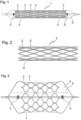
- Figure 1 shows a side view of an embodiment of the invention that has been crimped onto a dilatation balloon.
- the stent 1 consists of a plurality of ring elements 2 and 3 that are connected to one another by connecting elements 4. Ring elements 2 are located on the edge and each have only one neighbor, while ring elements 3 have either an edge or an inner ring element as a neighbor.
- the connecting elements 4 are connecting webs that start from the outer turning points of the ring elements and, in the case shown, run to the outer turning points of the neighboring ring element 3.
- the webs of the connecting elements 4 have perforations running in the direction of the longitudinal axis of the stent 1, which form a weakening zone that leads to a predetermined breaking point.
- the perforations continue through the adjacent parts of the webs of the ring segments 2, 3.
- the vascular support 1 is attached to a commercially available balloon 5, which can be transported to the site of use by means of a catheter and guide wire.
- Figure 2 shows the vascular support of Figure 1 in a first implanted state with slightly expanded ring segments 2, 3 and intact connecting elements 4. The dilatation balloon is removed from the vascular support 1.
- Figure 3 Finally, the vascular support of Figure 1 and 2 on a dilatation balloon 5.
- the dilatation balloon has a larger radius and can thus spread the stent 1 further until the perforation line 8, which runs parallel to the longitudinal axis of the stent 1, tears or breaks open.
- markers 6 which are arranged proximally and distally to the vascular support 1.
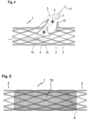
- Figure 4 shows the vascular support 1 of Figure 2 and a dilatation balloon 5 inserted therein, which has been passed laterally through the wall of the vascular support 1 and dilated. Accordingly, the predetermined breaking points of the connecting bridges the affected ring elements 2 and 3 are broken open, so that a window is created through which a branching vessel can also be supplied with blood.
- perforation lines 15 running in the longitudinal direction of the vascular support 1 as well as notches 10 which run transversely thereto through the connecting webs 4 and allow the vascular support to be separated transversely to the longitudinal direction.
- the dilatation balloon 5 at the tip of the catheter 7 is advanced over a guide wire 17 and positioned specifically into the stent 1 already implanted in the area of a vessel branch, so that the stent is broken open in the area of the branch.
- Figure 5 shows the stent of Figure 2 with a tubular membrane 19 stretched over it, which serves, for example, to shield a vascular anomaly, such as an aneurysm or a perforation.
- the membrane 19 can, for example, consist of Teflon or another biocompatible material and can optionally be equipped with a medication.
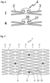
- Figure 6 shows connecting elements 4 according to the invention between ring elements 2, 3.
- the representations j and k show embodiments according to the invention in which the stent struts are arranged in the connecting element similar to a joint connection and are connected via a connecting web. This arrangement enables the setting of defined lever effects in the connecting element when the stent is expanded.
- Illustration j shows a simple embodiment, in illustration k a bending point 27 on the two-dimensional joint ball 26 is specified by the special arrangement.
- Figure 7 shows an embodiment of a vascular support 1 according to the invention in the spread-out state with a partial surface within which the connecting elements 4 between ring elements 3 are provided with predetermined breaking points.
- the zone intended for fenestration is delimited by four markers 6. Between these markers 6 all connecting elements 4 are provided with a Predetermined breaking point through perforation holes 15 arranged in a row in the longitudinal direction and with notches for generating a predetermined breaking point in the circumferential direction. When a catheter balloon expands in the area of this fenestration zone, the connecting elements 4 tear along the predetermined breaking points and open the window, for example into a side vessel.
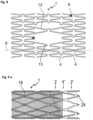
- Figure 8 shows a vascular support 1 according to the invention with webs 13 that are greatly extended in the central area in order to enable improved side branch access in the dilated state.
- the stent 1 can be split lengthwise along the dividing line 8, with the connecting elements 4 having two openings along this dividing line that bring about the weakening required for the splitting.
- Figure 9a /b shows a vascular support according to the invention with a covering 19 and predetermined breaking points in the connecting elements 4, which run both in the longitudinal direction and transversely thereto.
- the stent 1 has a ring element 2', which is connected to the peripheral ring element 2 of the stent 1 via connecting webs 4' and can be folded back onto the membrane 19.
- Fastening pins 24 serve to fix the membrane 19.
- Figure 10a /b shows a variant of the embodiment of Figure 9a /b, in which the end ring segment 2' is connected to the edge ring segments 2 via laterally offset connecting elements 4'.
- the diagonally extending connecting elements 4' facilitate the folding of the ring element 2' onto the membrane 19.
- inventions according to Figure 9 such as 10 have the predetermined breaking points according to the invention on the connecting elements 4 in the part of the stent 1 located under the membrane 19.
- FIG 11 shows in variants a to p a number of clamping elements 21 which serve to fix a membrane.
- the clamping elements 21 are webs which are notched out of a connecting element 4 or a ring element 2, 3 and which are resiliently movable against the connecting element or ring element. The membrane can thus be pushed under this resilient clamping element 21 and thereby fixed.
- the clamping elements 21 can advantageously be released from the connecting element 4 as well as from a ring element 2 or 3. These are freely movable webs of almost any shape. A widened end in the form of a star, hammer head or disk, a toothing or spikes serve to better secure a membrane.
- the clamping elements 21 can occur in pairs and run essentially in the longitudinal direction of the vascular support. In each case, a membrane is fixed by pushing it between the grid structure of the stent and the freely movable webs of the clamping elements 21, see Figure 12q.
- Figure 12 shows a vascular support 1 with a stent structure typical for heart valves with peripheral ring segments 2, adjacent ring segments 3 and connecting bars 4. Connecting bars are often designed as straight bars that run over the entire length of the stent 1 and thus define its length.
- connecting elements 34 are arranged in the area of the fracture lines 8 between the webs of the ring elements 2 and 3.
- the predetermined breaking points are formed by perforation lines that tear open during subsequent dilation and thus allow the valve to adapt to the growing vessels.
- the Figure 12 The stent 1 shown has resilient webs 21 which are suitable for fixing a heart valve-bearing stent in the surrounding vessel wall and thus prevent the stent from slipping. Furthermore, this stent can also other clamping elements as in Figure 11 a to q are included so that the flap material can be clamped in. This eliminates the need for the usual gluing, wiring or sewing of the fixed or movable flap parts.
- a second cushion-like membrane can also be advantageously clamped inside and outside with suitable clamping elements 21 for sealing purposes at the lower edge of the stent 1.
- Figure 13 shows a further embodiment of a vascular support which has clamping devices for fixing a heart valve-bearing membrane.
- the clamping devices can be one of the Figure 12 shown variant or a combination of these or other clamping devices according to the invention.
- Figure 14 shows an example of how a heart valve-bearing membrane can be transformed into a vascular support, as in Figure 14 shown, is trapped.
- Figure 15 shows a further embodiment of a vascular support which, in addition to clamping devices for fixing a heart valve-supporting membrane, has further clamping devices for receiving a further membrane lying on the outside of the vascular support.
Landscapes
- Health & Medical Sciences (AREA)
- Biomedical Technology (AREA)
- Engineering & Computer Science (AREA)
- Cardiology (AREA)
- Heart & Thoracic Surgery (AREA)
- Veterinary Medicine (AREA)
- Oral & Maxillofacial Surgery (AREA)
- Transplantation (AREA)
- Public Health (AREA)
- Vascular Medicine (AREA)
- Life Sciences & Earth Sciences (AREA)
- Animal Behavior & Ethology (AREA)
- General Health & Medical Sciences (AREA)
- Physics & Mathematics (AREA)
- Optics & Photonics (AREA)
- Prostheses (AREA)
- Media Introduction/Drainage Providing Device (AREA)
- Surgical Instruments (AREA)
Description
- Die Erfindung betrifft eine radial aufweitbare Gefäßstütze, welche eine Mehrzahl von miteinander flexibel verbundenen mäandrierenden Ringelementen aufweist, welche eine Gefäßstütze mit einem proximalen und einem distalen Ende und einer Längsachse definieren, wobei die Ringelemente entlang der Längsachse der Gefäßstütze nebeneinander angeordnet sind und aneinander grenzende Ringelemente durch Verbindungselemente miteinander verbunden sind.
- Die erfindungsgemäßen Gefäßstützen sind auf der ganzen Länge oder in Teilbereichen radial aufweitbare Stents zur Verwendung beim Offenhalten von Blutgefäßen oder sonstigen Organwegen in menschlichen oder tierischen Körpern.
- Gefäßstützen werden allgemein zur dauerhaften Stützung der Gefäßwand im Bereich von Stenosen implantiert, als Trägerstruktur von Membranen zum Offenhalten von Gefäßen oder von minimal invasiv implantierbaren Herzklappen. Sie werden auf einen zusammengefalteten Ballon aufgepresst und im Gefäß durch Ballondilatation auf einen bestimmten Durchmesser aufgedehnt.
- Da bei Kindern aber der maximal einführbare Kathederdurchmesser von einem Ballonkatheter mit montiertem Stent durch den limitierten Durchmesser der Zugangsgefäßkammer der Femoralarterie oder der Femoralvene, begrenzt ist, kann ein herkömmlicher Stent nur bis auf einen Durchmesser von maximal 6 bis 8 mm aufgedehnt werden. Da aber beispielsweise der Durchmesser einer Lungenarterie im Erwachsenenalter bis zu 30 mm betragen kann, müssten herkömmliche Stents mit relativ zu kleinem Durchmesser im Laufe des Wachstums chirurgisch mit einer Operation an der Herzlungenmaschine entfernt werden. Durch die erfindungsgemäßen Stents mit Sollbruchstellen wird dieser Nachteil vermieden, da sie nach Aufbrechen der Sollbruchstellen mit einem weiteren Ballon beliebig weit aufgedehnt werden können. Dann haben sie zwar kaum noch eine Radialfestigkeit, aber gegebenenfalls kann diese durch die Implantation eines weiteren Stents mit größerem Durchmesser erreicht werden.
- Andere redilatierbare Gefäßstützen weisen Nahtverbindungen zwischen zickzackförmigen Drahtgerüsten auf, wie beispielsweise gemäß
DE 101 03 000 , die sich nach einer gewissen Zeit auflösen und damit ein weiteres Gefäßwachstum erlauben. Nachteilig ist ein Verschieben der zusammengenähten Teilsegmente beim Crimpen auf einen Ballon und eine geringe Radialkraft. - Gemäß
US 5, 591, 223 A - In der
WO 2011/032526 A1 ist eine radial aufweitbare Gefäßstütze mit Dehnelementen beschrieben, die eine weitere Aufdehnung in einem großen Durchmesserbereich bei Erhalt der Radialkraft erlauben. Hier ist nachteilig, dass nach zirkulärer Aufdehnung und Bruch der Dehnelemente diese korkenzieherartig die Wand des Blutgefäßes perforieren können. - Aus der
US 5, 591, 223 A geht eine reexpandierbare Gefäßstütze hervor, die ein Ringsegment mit einer Wachstumsfuge aufweist. Die Wachstumsfuge wird durch Verbindungsstreifen überbrückt, die aus absorbierbarer Wundnaht bestehen können und zerreißen, wenn eine definierte Zugkraft ausgeübt wird. Die Verbindungsstreifen sind durch Schweißen, Löten oder Kleben am Ringsegment befestigt. - Die
EP 1 958 598 A1 beschreibt eine Stützprothese mit Sollbruchstellen gemäß Oberbegriff des Anspruchs 1. - Aufgabe der vorliegenden Erfindung ist es, eine radial aufweitbare Gefäßstütze zu schaffen, die während ihrer Aufweitung keine oder nur eine geringe Verkürzung erfährt, bei besserer Kurvengängigkeit weniger leicht knickt, eine ausreichende Radialfestigkeit aufweist und gleichzeitig durch Aufweiten zumindest von Teilstücken erneut dilatiert werden kann.
- Diese Aufgabe wird durch eine radial expandierbare Gefäßstütze mit den Merkmalen von Patentanspruch 1 gelöst.
- Die erfindungsgemäßen Gefäßstützen bestehen aus nebeneinander angeordneten Ringelementen, die mäandrierend oder zickzackförmig verlaufen, sowie Verbindungselementen, die nebeneinander liegende Ringelemente miteinander verbinden. Zumindest einige Verbindungselemente weisen Sollbruchstellen auf, die insbesondere parallel zur Längsachse der Gefäßstütze verlaufen, aber auch quer dazu verlaufen können. Ein Verbindungselement kann dabei sowohl längs als auch quer verlaufende Sollbruchstellen aufweisen. Schräg verlaufende Sollbruchstellen sind ebenfalls möglich. Insbesondere kommen aber längsverlaufende Sollbruchstellen infrage, die ein partielles oder vollständiges Öffnen des Stents bei einer Nachdilatation ermöglichen. Dazu erstrecken sich längs verlaufende Sollbruchstellen auch auf und über die Stege der Ringelemente, die durch die jeweiligen Verbindungselemente miteinander verbunden sind.
- Insgesamt besteht die erfindungsgemäße flexible radiale reexpandierbare Gefäßstütze aus einem gitterförmigen Stentgerüst mit einer mäandrierenden Ringstruktur von geringer Breite mit mehreren kreisförmig, linear, quer oder spiralig darauf angeordneten Sollbruchstellen in Form von Perforationslinien oder Einkerbungen. Bei der Herstellung und im ersten Implantationszustand bleiben diese Sollbruchstellen geschlossen und miteinander fest verbunden, können aber zu einem späteren Zeitpunkt durch eine weitere Ballondilatation in beliebiger Weise aufgebrochen werden.
- Durch das Aufbrechen der Verbindungselemente insgesamt oder in einzelnen Teilbereichen der Gefäßstütze zu einem späteren Zeitpunkt wird ein weiteres Wachstum des Gefäßes ermöglicht, gegebenenfalls auch durch eine weitere Ballondilatation oder die Implantation einer weiteren Gefäßstütze mit größerem Durchmesser in den Bereichen der bestehenden Gefäßstütze.
- Durch das seitliche Aufbrechen der Sollbruchstellen einer Gefäßstütze, beispielsweise im Bereich einer durch Markierungen besonders gekennzeichneten Zone mit Sollbruchstellen in den Verbindungselementen, kann durch lokale Aufdehnung in vorteilhafter Weise ein verbesserter Seitenastzugang geschaffen werden.
- Der verbesserte Seitenastzugang kann erfindungsgemäß sowohl durch Aufbrechen von Sollbruchstellen in Teilbereichen der Gefäßstütze als auch durch Anordnung von verlängerten Stentstreben oder Weglassen von Stentstreben erreicht werden.
- Ist die Gefäßstütze zusätzlich, etwa auf der Zirkumferenz, ganz oder in Teilbereichen mit einer biologischen oder synthetischen Membran gecovert, so kann deren Befestigung auf der Gefäßstütze durch Vernähen, Verkleben, aber auch mit speziellen Klemm- und Clipelementen erfolgen. Diese eignen sich auch zur Befestigung von biologischem oder synthetischem Gewebe, Membranen oder Folien und für mit Laser geschnittenen Schirmsystemen zum Verschließen von Herzwanddefekten. Gleiches gilt für implantierbare Herzklappen.
- Ist die Gefäßstütze mit einer Membran gecovert, so ist es besonders vorteilhaft, die beiden jeweils äußeren Ringelemente nicht zu covern, damit es beim Aufdehnen der Gefäßstütze an den Enden nicht zu einem Membranprolabs kommt.
- Die erfindungsgemäßen Gefäßstützen weisen eine Mehrzahl von Verbindungselementen mit Sollbruchfunktion auf. Diese Sollbruchfunktionen können beispielsweise auf die Verbindungselemente von nur zwei benachbarten Ringelementen begrenzt sein, um beispielsweise eine Auftrennung oder Aufklappung der Gefäßstütze zu erreichen, sie können aber auch zwischen einer Mehrzahl von Ringelementen angeordnet sein, um beispielsweise einen Bereich zu definieren und auf diese Art und Weise Fenestrierungen zu ermöglichen. Eine weitere Variante ist die Anordnung der Sollbruchstellen über die Länge der Gefäßstütze, so dass diese insgesamt vollständig oder partiell aufgetrennt werden kann. Dabei können die Sollbruchstellen parallel zur Längsachse der Gefäßstütze angeordnet sein, aber auch einer Helix-Linie, die sich um die Gefäßstütze erstreckt, folgen.
- Von besonderem Interesse sind Sollbruchstellen, die auf allen Verbindungselementen in einem Teilbereich des Stents angeordnet sind und damit die Öffnung eines Fensters ermöglichen, etwa im Bereich eines abgehenden Blutgefäßes. In diesem Fall ist es zweckmäßig, die Sollbruchstellen sowohl in Längsrichtung der Streckung der Gefäßstütze als auch quer dazu anzuordnen, um einen Bereich öffnen zu können.
- Soweit die erfindungsgemäßen Gefäßstützen mit einer Membran versehen sind, die mit der Gefäßstütze vernäht ist, können Fäden aus resorbierbarem Material oder Reineisen- oder Wolframdraht verwandt werden. Die Membran selbst kann aus einem biologischen oder synthetischen Material bestehen. Letzteres kann durch Elektrospinnen appliziert worden sein.
- Um bei den erfindungsgemäßen Gefäßstützen die Längenreduktion bei der Aufweitung in Grenzen zu halten, können eine Mehrzahl von Ringsegmenten über spiralförmige, s-förmige oder bogenförmige Verbindungselemente mit benachbarten Ringelementen verbunden sein, die sich bei der Dilatation strecken. Bevorzugt in diesem Zusammenhang sind ferner paarweise in gegensätzlicher Richtung angeordnete bogenförmige Verbindungselemente, die zusammen mit den angrenzenden Streben der Ringelemente ein sternförmiges Element ergeben. Dadurch ergibt sich trotz hoher Flexibilität durch die multizelluläre Struktur eine hohe Radialfestigkeit, die durch spiralige oder abwechselnde Anordnung von einem oder mehreren sternförmigen Segmenten noch erhöht wird. Auch durch derartige Ausbildungen wird das Biegeverhalten der Gefäßstütze insgesamt günstig beeinflusst.
- Die Verbindungselemente sind dergestalt ausgeführt, dass der Bruch der Sollbruchstellen über einen Hebel im Verbindungselement herbeigeführt wird. Der Steg ist am Verbinder dann beispielsweise in Form einer zweidimensionalen Gelenkkugel und Gelenkpfanne angebracht, wobei beide Elemente durch einen Verbindungssteg - der Sollbruchstelle - zwischen zweidimensionaler Gelenkkugel und -pfanne verbunden sind. Dies hat den Vorteil, dass die Ausführung der Sollbruchstelle stabiler sein kann, da die auf diese Stelle bei Überdehnung eine Hebelkraft wirkt. Dieser Bereich weist entsprechend beim nicht überdehnten Stent eine höhere Festigkeit auf. Eine Überdehnung führt dabei ebenfalls und gegebenenfalls sogar leichter und in jedem Fall aber definiert zu einem Bruch der Sollbruchstelle. Tatsächlich ist es möglich, die zum Bruch der Sollbruchstelle notwendige Kraft in einem gegebenen Rahmen durch Wahl des Hebels vorzugeben. Vorteilhaft ist auch, dass eine solche Ausführung der Sollbruchstelle über einen Hebel eine präzise Winkelbegrenzung der maximal möglichen Aufdehnung des Stents ohne Bruch in den entsprechenden Verbindern erlaubt, was durch vorgegebene Einrastpunkte zusätzlich definiert werden kann. Die Stege der Verbindungselemente zwischen den einzelnen Ringelementen weisen vorzugsweise einen etwas geringeren Querschnitt auf als die Stege der mäandrierenden oder zickzackförmigen Ringelemente. Der Stegquerschnitt der Verbindungstege beträgt dann etwa 60 bis 80% des Querschnitts der Stege der Ringelemente. Es sind beliebige Kombinationsmöglichkeiten mit den verschiedenen Formen von Stegen der Verbindungselemente denkbar.
- Soweit die Sollbruchstellen aus Einkerbungen bestehen, haben diese in der Regel eine Tiefe von 30 bis 50% der Stegdicke der Verbindungselemente, auf denen sie angeordnet sind. Perforationen, die in der Regel linear angeordnet sind, haben einen Durchmesser etwa von 20 bis 60% der Stegbreite der entsprechenden Verbindungselemente. Die Perforationen können rund, dreieckig, rechteckig oder sternförmig ausgebildet sein.
- Als Material für die erfindungsgemäße Gefäßstütze können übliche Materialien verwandt werden, insbesondere biokompatible Metalle wie Eisen, Stahl, Wolfram, Niob, Platin, Titan, Legierungen von Nickel und Titan sowie Legierungen mit mindestens einem dieser Metalle, wie Platin-Iridium. Soll die Gefäßstütze selbst expandierbar sein, wird vorzugsweise eine durch Wärmebehandlung temperaturoptimierte Nickel-Titan-Legierung verwandt.
- Die Gefäßstütze kann zur Verbesserung des Einwachsens in die Gefäßwand mit einem biokompatiblen Material oder mit geeigneten Medikamenten zur Vermeidung von Hyperproliferation der Gefäßwand beschichtet sein oder durch Bestrahlung oder radioaktiven Zerfall eine Strahlung freisetzen.
- Ferner kann die Gefäßstütze oder die Bespannung auch aus resorbierbaren Kunststoffen, z. B. aliphatischen Polyestern wie Polydioxanon, bestehen.
- Die erfindungsgemäßen Gefäßstützen werden vorzugsweise aus nahtlos gezogenen Rohren gebildet, um Verspannungen und Risse zu vermeiden, wie das im Bereich von Schweißnähten häufig der Fall ist. Die Strukturen werden vorzugsweise durch Laser- oder Wasserstrahlschneiden, Elektroerosion und Elektropolitur hergestellt. Die Gefäßstützen haben im Erstehungszustand eine gitterförmige Struktur, die durch Crimpen auf einen Dilatationsballon komprimiert werden kann und nach der Implantation durch Dilatation über den ursprünglichen Zustand nach der Herstellung hinaus aufgeweitet werden kann. Die Sollbruchstellen werden in der Regel erst mit einer Nach- oder Redilatation aktiviert und zum Aufreißen gebracht. Je nach Verwendung der erfindungsgemäßen Gefäßstütze mit ihren verschiedenen Ausführungsformen kann in speziellen Fällen auch auf Sollbruchstellen verzichtet werden.
- Sofern die Verbindungselemente als reine Klemmvorrichtungen für Membranen angelegt sind, kann in diesen speziellen Fällen auf Sollbruchstellen innerhalb der Klemmen verzichtet werden.
- Weitere Merkmale und Vorteile der Erfindung ergeben sich aus der nachfolgenden Beschreibung von Ausführungsbeispielen anhand der Abbildungen, die erfindungswesentliche Einzelheiten zeigen sowie aus den Ansprüchen. Die einzelnen Merkmale können hier einzeln für sich oder zu mehreren beliebigen Kombinationen bei Varianten der Erfindung verwirklicht sein. Es versteht sich, dass Abbildungen nur Beispiele sind und dass jedes in einer Abbildung gezeigte besondere Merkmal in beliebiger Kombination mit Merkmalen aus anderen Abbildungen zur Erfindung gehört.
- Von den Abbildungen zeigen:
- Fig.1:
- Eine Seitenansicht einer Ausführungsform der Erfindung, die auf einen Dilatationsballon gecrimpt wurde;
- Fig. 2:
- eine Seitenansicht der gleichen Ausführungsform, wie
Fig. 1 in einem ersten aufgedehnten Zustand, nachdem der Dilatationsballon entfernt wurde; - Fig. 3:
- in einer weiteren Seitenansicht die Ausführungsform von
Fig. 1 und 2 bei der maximalen Aufdehnung mit einem druckfesten Dilatationsballon mit einem größeren Durchmesser und aufgebrochenen Sollbruchstellen; - Fig. 4:
- in einer Seitenansicht die Ausführungsform der Erfindung gemäß
Fig. 2 bei Durchführung einer Fenestrierung; - Fig. 5:
- die Ausführungsform gemäß
Fig. 2 , gecovert mit einer membranartigen Folie; - Fig. 6:
- Verbindungselemente, wie sie erfindungsgemäß zum Einsatz kommen;
- Fig. 7:
- eine Gefäßstütze in ausgebreitetem Zustand mit einem durch Verbindungstege mit Sollbruchstellen definierten Bereich für Fenestrierungen;
- Fig. 8:
- eine Variante einer erfindungsgemäßen Gefäßstütze mit verlängerten Stegen im zentralen Bereich;
- Fig. 9:
- eine erfindungsgemäße Gefäßstütze mit über die Endsegmente fixierbarer Membran;
- Fig. 10:
- eine weitere Variante der Ausführungsform von
Fig. 14 ; - Fig. 11:
- Varianten von Klemmelementen, mit denen eine Membran auf der Gefäßstütze fixiert werden kann; und
- Fig. 12:
- eine erfindungsgemäße Gefäßstütze, die beispielsweise für Herzklappenimplantate eingesetzt werden kann.
- Fig. 13:
- eine weitere erfindungsgemäße Gefäßstütze, die beispielsweise für Herzklappenimplantate eingesetzt werden kann.
- Fig. 14:
- die erfindungsgemäße Gefäßstütze gemäß
Figur 14 mit einer eingespannten Membran mit Herzklappe. - Fig. 15:
- eine weitere Variante einer erfindungsgemäßen Gefäßstütze, die beispielsweise für Herzklappenimplantate eingesetzt werden kann und zusätzliche Klemmelemente für eine weitere Membran aufweist.
-
Figur 1 zeigt eine Seitenansicht einer Ausführungsform der Erfindung, die auf einen Dilatationsballon gecrimpt wurde. Die Gefäßstütze 1 besteht aus einer Vielzahl von Ringelementen 2 und 3, die durch Verbindungselemente 4 miteinander verbunden sind. Ringelemente 2 sind randständig und haben jeweils nur einen Nachbarn, während Ringelemente 3 entweder ein randständiges oder ein innenständiges Ringelement zum Nachbarn haben. Die Verbindungselemente 4 sind Verbindungsstege, die von den äußeren Wendepunkten der Ringelemente ausgehen und im dargestellten Fall zu den äußeren Wendepunkten des benachbarten Ringelements 3 verlaufen. - Die Stege der Verbindungselemente 4 weisen in Richtung der Längsachse der Gefäßstütze 1 verlaufende Perforationen auf, die eine Schwächungszone ausbilden, die zur einer Sollbruchstelle führt. Die Perforationen setzen sich durch die angrenzenden Teile der Stege der Ringsegmente 2, 3 hindurch fort.
- Die Gefäßstütze 1 ist auf einen handelsüblichen Ballon 5 aufgebracht, der mittels Katheter und Führungsdraht an den Einsatzort transportiert werden kann.
-
Figur 2 zeigt die Gefäßstütze vonFigur 1 in einem ersten implantierten Zustand mit leicht aufgeweiteten Ringsegmenten 2, 3 und intakten Verbindungselementen 4. Der Dilatationsballon ist aus der Gefäßstütze 1 entfernt. -
Figur 3 schließlich zeigt die Gefäßstütze vonFigur 1 und 2 auf einem Dilatationsballon 5. In diesem hat der Dilatationsballon einen größeren Radius und kann damit die Gefäßstütze 1 weiter aufspreizen, bis zum Aufreißen bzw. Aufbrechen der Perforationslinie 8, die parallel zur Längsachse der Gefäßstütze 1 verläuft. - Zur exakten Positionierung des Implantats bzw. des Dilatationsballons ist dieser mit Markern 6 ausgestattet, die proximal und distal zur Gefäßstütze 1 angeordnet sind.
- Die in
Figur 3 dargestellte Seitenansicht der Gefäßstütze 1 mit Aufweitung auf einen maximalen Durchmesser und aufgebrochenen Verbindungselementen 4 entlang der Perforationslinie 8, die parallel zur Längsachse der Gefäßstütze 1 verläuft, führt zwar zu einer Gefäßstütze 1 mit reduzierter Radialkraft, erlaubt aber danach ein weiteres Wachstum des Durchmessers des entsprechenden Gefäßes, etwa der Aorta oder der Pulmonalarterie eines im Wachstum befindlichen Kindes. Gegebenenfalls kann in die aufgebrochene Gefäßstütze 1 eine weitere Gefäßstütze mit einem größeren maximalen Enddurchmesser implantiert werden. -
Figur 4 zeigt die Gefäßstütze 1 vonFigur 2 und einen darin eingeführten Dilatationsballon 5, der seitlich durch die Wand der Gefäßstütze 1 hindurchgeführt und dilatiert worden ist. Entsprechend sind die Sollbruchstellen der Verbindungsstege der betroffenen Ringelemente 2 und 3 aufgebrochen, so dass ein Fenster entsteht, durch das auch ein abzweigendes Gefäß mit Blut versorgt werden kann. - Deutlich dargestellt sind die in Längsrichtung der Gefäßstütze 1 verlaufenden Perforationslinien 15 sowie Einkerbungen 10, die quer dazu durch die Verbindungsstege 4 verlaufen und eine Auftrennung der Gefäßstütze quer zur Längsrichtung erlauben.
- Der Dilatationsballon 5 an der Spitze des Katheters 7 wird über einen Führungsdraht 17 vorgeschoben und gezielt in den bereits in den Bereich einer Gefäßabzweigung implantierten Stent 1 positioniert, so dass dieser im Bereich der Abzweigung aufgebrochen wird.
-
Figur 5 zeigt den Stent vonFigur 2 mit einer darüber gespannten schlauchförmigen Membran 19, die beispielsweise dazu dient, eine Gefäßanomalie, etwa ein Aneurysma oder eine Perforation, abzuschirmen. Die Membran 19 kann beispielsweise aus Teflon oder einem anderen körperverträglichen Material bestehen und gegebenenfalls mit einem Medikament ausgestattet sein. -
Figur 6 zeigt erfindungsgemäße Verbindungselemente 4 zwischen Ringelementen 2, 3. Die Darstellungen j und k zeigen erfindungsgemäße Ausführungsformen, bei denen die Stentstruts im Verbindungselement ähnlich einer Gelenkverbindung angeordnet und über einen Verbindungssteg verbunden sind. Diese Anordnung ermöglicht die Einstellung von definierten Hebelwirkungen im Verbindungselement bei Aufdehnung des Stents. Darstellung j zeigt eine einfache Ausführungsform, in Darstellung k wird durch die spezielle Anordnung ein Knickpunkt 27 an der zweidimensionalen Gelenkkugel 26 vorgegeben. -
Figur 7 zeigt eine Ausführungsform einer erfindungsgemäßen Gefäßstütze 1 in ausgebreitetem Zustand mit einer Teilfläche, innerhalb derer die Verbindungselemente 4 zwischen Ringelementen 3 mit Sollbruchstellen versehen sind. - Die Zone, die für die Fenestrierung vorgesehen ist, ist durch vier Marker 6 eingegrenzt. Zwischen diesen Markern 6 sind alle Verbindungselemente 4 mit einer Sollbruchstelle durch aneinander gereihte Perforationslöcher 15 in Längsrichtung und mit Kerben zur Generierung einer Sollbruchstelle in Umfangsrichtung ausgestattet. Bei Expansion eines Katheterballons im Bereich dieser Fenestrierungszone reißen die Verbindungselemente 4 entlang der Sollbruchstellen auf und öffnen das Fenster, beispielsweise in ein Seitengefäß hinein.
- Die Gefäßstütze gemäß
Figur 7 weist in den Bereichen, in denen keine Sollbruchstellen in den Verbindungselementen 4 vorgesehen sind, die gekrümmten Verbindungselemente 4, auf die paarweise mit ihren offenen Seiten einander zugewandt sind und mit den angrenzenden Schlingen der Ringelemente 2, 3 ein sternförmiges Design ergeben, das für eine gute Radialkraft steht. -
Figur 8 zeigt eine erfindungsgemäße Gefäßstütze 1 mit im zentralen Bereich stark verlängerten Stegen 13, um so im dilatierten Zustand einen verbesserten Seitenastzugang zu ermöglichen. Der Stent 1 ist entlang der Trennlinie 8 längs auftrennbar, wobei entlang dieser Trennlinie die Verbindungselemente 4 zwei Durchbrechungen aufweisen, die die für die Auftrennung nötige Schwächung herbeiführen. -
Figur 9a /b zeigt eine erfindungsgemäße Gefäßstütze mit einer Bespannung 19 und Sollbruchstellen in den Verbindungselementen 4, die sowohl in Längsrichtung als auch quer dazu verlaufen. Zur Fixierung der Membran 19 weist der Stent 1 ein Ringelement 2' auf, das über Verbindungsstege 4' an das randständige Ringelement 2 des Stents 1 angebunden ist und auf die Membran 19 zurückgeklappt werden kann. Befestigungsdorne 24 dienen der Fixierung der Membran 19. -
Figur 10a /b zeigt eine Variante der Ausführungsform vonFigur 9a /b, bei der das endständige Ringsegment 2' über seitlich versetzte Verbindungselemente 4' mit den randständigen Ringsegmenten 2 verbunden ist. Die schräg seitlich verlaufenden Verbindungselemente 4' erleichtern das Umklappen des Ringelements 2' auf die Membran 19. - Die Ausführungsformen gemäß
Figur 9 wie 10 weisen in dem unter der Membran 19 liegenden Teil des Stents 1 die erfindungsgemäßen Sollbruchstellen an den Verbindungselementen 4 auf. -
Figur 11 zeigt in den Varianten a bis p eine Vielzahl von Klemmelementen 21, die der Fixierung einer Membran dienen. Die Klemmelemente 21 sind aus einem Verbindungselement 4 oder einem Ringelement 2, 3 ausgeklinkte Stege, die gegen das Verbindungselement oder Ringelement federnd beweglich sind. Die Membran kann damit unter dieses federnde Klemmelement 21 geschoben und dadurch fixiert werden. - Die Klemmelemente 21 können vorteilhaft sowohl aus dem Verbindungselement 4 wie auch aus einem Ringelement 2 oder 3 ausgeklinkt werden. Es handelt sich dabei um freibewegliche Stege mit nahezu beliebiger Form. Ein verbreitertes Ende in Form eines Sterns, Hammerkopfes oder einer Scheibe, einer Zähnung oder Dornen dienen der besseren Befestigung einer Membran. Die Klemmelemente 21 können paarweise auftreten und verlaufen im Wesentlichen in Längsrichtung der Gefäßstütze. In jedem Fall wird eine Membran durch Einschieben zwischen die Gitterstruktur des Stents und den freibeweglichen Stegen der Klemmelemente 21 fixiert, siehe Figur 12q.
-
Figur 12 zeigt eine Gefäßstütze 1 mit einer für Herzklappen typischen Stentstruktur mit randständigen Ringsegmenten 2, daran angrenzenden Ringsegmenten 3 sowie Verbindungsstegen 4. Verbindungsstege sind hier vielfach als gerade Stege ausgebildet, die über die gesamte Länge des Stents 1 verlaufen und damit dessen Länge definieren. - Im dargestellten Fall sind Verbindungselemente 34 im Bereich der Bruchlinien 8 zwischen Stegen der Ringelemente 2 und 3 angeordnet. Die Sollbruchstellen werden durch Perforationslinien gebildet, die bei Nachdilatation aufreißen und damit eine Anpassung der Klappe an die wachsenden Gefäße erlauben.
- Der in
Figur 12 dargestellte Stent 1 weist federnde Stege 21 auf, die sich zur Fixierung eines Herzklappen tragenden Stents in der umgebenden Gefäßwand eignen und so ein Verrutschen des Stents verhindern. Ferner kann dieser Stent auch weitere Klemmelemente wie sie inFigur 11 a bisq dargestellt sind enthalten, damit das Klappenmaterial eingeklemmt werden kann. Auf diese Weise entfällt das sonst übliche Verkleben, Verdrahten oder einnähen der festen oder beweglichen Klappenteile. - Zur Verringerung von paravalvulären Leckagen kann so vorteilhaft einfach auch noch eine zweite polsterartige Membran nur zur Abdichtung am Unterrand des Stents 1 mit geeigneten Klemmelementen 21 innen und außen eingeklemmt werden.
-
Figur 13 zeigt eine weitere Ausführungsform einer Gefäßstütze, die Klemmvorrichtungen zur Fixierung einer Herzklappen-tragenden Membran aufweist. Die Klemmvorrichtungen können einer der inFigur 12 dargestellten Variante oder auch einer Kombination dieser oder sonstiger erfindungsgemäßer Klemmvorrichtungen entsprechen. -
Figur 14 zeigt beispielhaft, wie eine Herzklappen-tragende Membran in eine Gefäßstütze, wie inFigur 14 dargestellt, eingeklemmt wird. - Figur 15 zeigt eine weitere Ausführungsform einer Gefäßstütze, die neben Klemmvorrichtungen zur Fixierung einer Herzklappen-tragenden Membran weitere Klemmvorrichtungen zur Aufnahme einer weiteren, der Außenseite der Gefäßstütze aufliegenden Membran aufweist. Zusätzlich befinden sich an den nach außen weisenden Bögen der randständigen Ringelemente Ösen, durch die beispielsweise ein oder mehrere Fäden gezogen werden können, um eine bereits expandierte Gefäßstütze beispielsweise im Rahmen einer Explantation oder Repositionierung wieder in einen Katheter zurückzuziehen zu können.
Claims (17)
- Radial aufweitbare Gefäßstütze (1), welche eine Mehrzahl von miteinander flexibel verbundenen mäandrierenden und aus Stegen aufgebauten Ringelementen (2, 3) aufweist, welche eine Gefäßstütze (1) mit einem proximalen und einem distalen Ende und einer Längsachse definieren, wobei die Ringelemente (2, 3) entlang der Längsachse der Gefäßstütze nebeneinander angeordnet sind und aneinander grenzende Ringelemente (2, 3) durch Verbindungselemente (4) miteinander verbunden sind, wobei zwischen wenigstens zwei aneinander grenzenden Ringelementen (2, 3) Verbindungselemente (4) angeordnet sind, die jeweils mindestens ein aufdehnbares Erweiterungselement mit Sollbruchstelle (10) aufweisen, wobei die Erweiterung in Längs- und/oder in Querrichtung möglich ist und die Sollbruchstellen (10) erst nach einer Überdehnung des Erweiterungselements über dessen maximalen Erweiterungspunkt hinaus brechen, dadurch gekennzeichnet, dass die Stege zumindest jeweils eines Ringelements (2, 3) im Verbindungselement (4) ähnlich einer zweidimensionalen Gelenkverbindung mit einer Gelenkkugel und einer Gelenkpfanne angeordnet und über eine Sollbruchstelle (10) mit dem Verbindungselement (4) verbunden sind und der Bruch der Sollbruchstelle (10) über einen Hebel im Verbindungselement (4) herbeigeführt wird.
- Gefäßstütze nach Anspruch 1, gekennzeichnet durch Verbindungsstege innerhalb der Verbindungselemente (4), die so angeordnet sind, dass sich die Erweiterungselemente stufenweise erweitern lassen.
- Gefäßstütze nach Anspruch 1 oder 2, dadurch gekennzeichnet, dass die Sollbruchstellen (10) an den Verbindungselementen (4) in Richtung der Längs- oder Querachse der Gefäßstütze oder helixförmig verlaufen.
- Gefäßstütze nach einem der vorstehenden Ansprüche, dadurch gekennzeichnet, dass die Sollbruchstellen (10) Einkerbungen sind, die 20 bis 70% der Stegdicke des Verbindungselements (4) ausmachen.
- Gefäßstütze nach einem der Ansprüche 1 bis 3, dadurch gekennzeichnet, dass die Sollbruchstellen (10) entlang einer Linie verlaufende Perforationslöcher sind, deren Durchmesser 20 bis 70% der Stegbreite der Verbindungselemente (4) ausmacht.
- Gefäßstütze nach einem der vorstehenden Ansprüche, dadurch gekennzeichnet, dass die Verbindungselemente (11) als Dehnungselemente (11) bogenförmig ausgebildet sind, wobei zwei aneinander grenzende gegenläufige Dehnungselemente (11) mit den angrenzenden Ringelementen (2, 3) ein sternförmiges Segment bilden.
- Gefäßstütze nach einem der vorstehenden Ansprüche, dadurch gekennzeichnet, dass die quer zur Längsrichtung verlaufenden Sollbruchstellen (10) um die Zirkumferenz des Stents herum ausgerichtet sind, um den Stent ganz oder teilweise zu teilen.
- Gefäßstütze nach einem oder mehreren der vorstehenden Ansprüche, dadurch gekennzeichnet, dass die Sollbruchstellen (10) dergestalt angeordnet sind, dass sie das Aufbrechen eines Fensters in der Gefäßstütze ermöglichen.
- Gefäßstütze nach Anspruch 8, gekennzeichnet durch gegenüberliegende Marker im Bereich der möglichen Fenistrierungen.
- Gefäßstütze nach einem der vorstehenden Ansprüche mit einer darauf aufgebrachten Membran, die vorzugsweise das äußere Ringelement (2) freilässt.
- Gefäßstütze nach Anspruch 10, dadurch gekennzeichnet, dass die Membran zwischen dem äußeren Ringelement (2) und dem anliegenden Ringelement (3) durch Umklappen des Ringelements (2) fixiert werden kann.
- Gefäßstütze nach Anspruch 11, dadurch gekennzeichnet, dass die Membran durch Elektrospinnen erzeugt ist.
- Gefäßstütze nach Anspruch 10, dadurch gekennzeichnet, dass die Membran schlauchförmig ausgebildet und durch Elektrospinnen erzeugt ist und durch Klemmelemente insbesondere an den Ringelementen (2, 3) fixiert ist.
- Gefäßstütze nach Anspruch 13, dadurch gekennzeichnet, dass die Ringelemente (2, 3) eine zweite Reihe Klemmelemente aufweisen, wobei an den beiden inneren Reihen von Klemmelementen eine erste Membran im Inneren der Gefäßstütze (1) befestigt werden kann und an den beiden äußeren Reihen von Klemmelementen ein zweite Membran an der Außenseite der Gefäßstütze (1) befestigt werden kann.
- Gefäßstütze nach einem der Ansprüche 10 bis 14, dadurch gekennzeichnet, dass mindestens eine Membran 2 oder 3 klappenartige Strukturen aufweist und durch Nähte, verkleben und/oder mit Klemmelementen an der Gefäßstütze (1) befestigt ist, wobei die Gefäßstütze im unteren Bereich eine zweite polsterförmige Membran aufweisen kann.
- Gefäßstütze nach Anspruch 15, dadurch gekennzeichnet, dass sich an den nach außen weisenden Bögen der randständigen Ringelemente Ösen beispielweise zur Aufnahme eines oder mehrerer Fäden befinden, um eine bereits expandierte Gefäßstütze wieder in einen Katheter zurückziehen zu können.
- Gefäßstütze nach einem der vorstehenden Ansprüche, dadurch gekennzeichnet, dass sie zumindest in Teilbereichen mit einer antiproliferativen oder gerinnungshemmenden Beschichtung versehen ist.
Priority Applications (1)
| Application Number | Priority Date | Filing Date | Title |
|---|---|---|---|
| EP24189545.7A EP4454607A3 (de) | 2015-06-03 | 2016-06-03 | Gefässstütze |
Applications Claiming Priority (2)
| Application Number | Priority Date | Filing Date | Title |
|---|---|---|---|
| DE102015108835.5A DE102015108835A1 (de) | 2015-06-03 | 2015-06-03 | Gefäßstütze |
| PCT/EP2016/062684 WO2016193449A1 (de) | 2015-06-03 | 2016-06-03 | GEFÄßSTÜTZE |
Related Child Applications (1)
| Application Number | Title | Priority Date | Filing Date |
|---|---|---|---|
| EP24189545.7A Division EP4454607A3 (de) | 2015-06-03 | 2016-06-03 | Gefässstütze |
Publications (3)
| Publication Number | Publication Date |
|---|---|
| EP3302373A1 EP3302373A1 (de) | 2018-04-11 |
| EP3302373C0 EP3302373C0 (de) | 2024-08-07 |
| EP3302373B1 true EP3302373B1 (de) | 2024-08-07 |
Family
ID=56263655
Family Applications (2)
| Application Number | Title | Priority Date | Filing Date |
|---|---|---|---|
| EP16732459.9A Active EP3302373B1 (de) | 2015-06-03 | 2016-06-03 | Gefässstütze |
| EP24189545.7A Pending EP4454607A3 (de) | 2015-06-03 | 2016-06-03 | Gefässstütze |
Family Applications After (1)
| Application Number | Title | Priority Date | Filing Date |
|---|---|---|---|
| EP24189545.7A Pending EP4454607A3 (de) | 2015-06-03 | 2016-06-03 | Gefässstütze |
Country Status (7)
| Country | Link |
|---|---|
| US (1) | US10905573B2 (de) |
| EP (2) | EP3302373B1 (de) |
| JP (1) | JP7075660B2 (de) |
| CN (1) | CN107872968B (de) |
| DE (1) | DE102015108835A1 (de) |
| ES (1) | ES2988896T3 (de) |
| WO (1) | WO2016193449A1 (de) |
Families Citing this family (24)
| Publication number | Priority date | Publication date | Assignee | Title |
|---|---|---|---|---|
| US6878162B2 (en) | 2002-08-30 | 2005-04-12 | Edwards Lifesciences Ag | Helical stent having improved flexibility and expandability |
| US20060074480A1 (en) | 2004-09-01 | 2006-04-06 | Pst, Llc | Stent and method for manufacturing the stent |
| US9456911B2 (en) * | 2006-02-14 | 2016-10-04 | Angiomed Gmbh & Co. Medizintechnik | Highly flexible stent and method of manufacture |
| DE102015115891A1 (de) * | 2015-09-21 | 2017-03-23 | Bentley Innomed Gmbh | Stent-Graft |
| US11622872B2 (en) | 2016-05-16 | 2023-04-11 | Elixir Medical Corporation | Uncaging stent |
| US12599490B2 (en) | 2017-05-25 | 2026-04-14 | Elixir Medical Corporation | Uncaging stent |
| CN112773583B (zh) * | 2017-08-11 | 2024-01-09 | 万能医药公司 | 撑开支架 |
| US11071626B2 (en) * | 2018-03-16 | 2021-07-27 | W. L. Gore & Associates, Inc. | Diametric expansion features for prosthetic valves |
| US10702407B1 (en) * | 2019-02-28 | 2020-07-07 | Renata Medical, Inc. | Growth stent for congenital narrowings |
| CN114727836B (zh) | 2019-11-14 | 2026-01-09 | 爱德华兹生命科学公司 | 经导管的医疗植入物递送 |
| DE102019135453A1 (de) * | 2019-12-20 | 2021-06-24 | Malte Neuss | Mehrfachstent mit Membran |
| DE102020211175A1 (de) | 2020-09-04 | 2022-03-10 | Carl Zeiss Meditec Ag | Stent-Implantat zur Glaukom-Behandlung durch Kammerwasserdrainage aus der Vorderkammer |
| CN114469470B (zh) * | 2020-10-26 | 2023-06-02 | 元心科技(深圳)有限公司 | 支架 |
| CN113151980A (zh) * | 2021-03-19 | 2021-07-23 | 苏州大学 | Ptfe管状覆膜支架及其制备方法 |
| WO2022245435A1 (en) | 2021-05-20 | 2022-11-24 | Cook Medical Technologies Llc | Self expanding stent and method of loading same into a catheter |
| US12263104B2 (en) * | 2021-05-20 | 2025-04-01 | Cook Medical Technologies Llc | Self expanding stents and methods |
| CN217723819U (zh) * | 2021-05-21 | 2022-11-04 | 爱德华兹生命科学公司 | 植入物相邻传感器锚定 |
| CN116407335A (zh) * | 2021-12-31 | 2023-07-11 | 先健科技(深圳)有限公司 | 覆膜支架及覆膜支架输送系统 |
| ES2914516A1 (es) * | 2022-01-07 | 2022-06-13 | Conic Vascular Espana Sl | Stent pediatrico autoexpandible |
| EP4518798A1 (de) * | 2022-05-06 | 2025-03-12 | St. Jude Medical, Cardiology Division, Inc. | Abnehmbare zellenkonfiguration für ventil in einem ventil |
| CN115192313B (zh) * | 2022-06-24 | 2024-03-26 | 柏为(武汉)医疗科技股份有限公司 | 一种可拼接外耳道支架 |
| CN115670740A (zh) * | 2022-10-10 | 2023-02-03 | 上海腾复医疗科技有限公司 | 一种血管网架结构 |
| WO2024124034A1 (en) | 2022-12-09 | 2024-06-13 | Renata Medical, Inc. | Transcatheter growth devices and methods for norwood, glenn and fontan therapy |
| CN116370168B (zh) * | 2023-05-31 | 2023-08-04 | 昆明理工大学 | 基于多圆弧星形胞元结构的血管支架结构、泊松比调节方法 |
Family Cites Families (31)
| Publication number | Priority date | Publication date | Assignee | Title |
|---|---|---|---|---|
| US5383926A (en) | 1992-11-23 | 1995-01-24 | Children's Medical Center Corporation | Re-expandable endoprosthesis |
| US7029492B1 (en) * | 1999-03-05 | 2006-04-18 | Terumo Kabushiki Kaisha | Implanting stent and dilating device |
| WO2000071053A1 (de) * | 1999-05-19 | 2000-11-30 | Eurocor Gmbh | Radial expandierbare gefässstütze |
| US6458153B1 (en) * | 1999-12-31 | 2002-10-01 | Abps Venture One, Ltd. | Endoluminal cardiac and venous valve prostheses and methods of manufacture and delivery thereof |
| EP1700581A3 (de) * | 2000-03-09 | 2006-09-20 | Design & Performance - Cyprus Limited | Stentvorrichtung mit Ösen zur Befestigung eines Transplantates |
| US8034097B2 (en) * | 2000-05-22 | 2011-10-11 | Malte Neuss | Radially expandable vessel support |
| DE10103000B4 (de) | 2001-01-24 | 2007-08-30 | Qualimed Innovative Medizinprodukte Gmbh | Radial reexpandierbare Gefäßstütze |
| US7550004B2 (en) * | 2002-08-20 | 2009-06-23 | Cook Biotech Incorporated | Endoluminal device with extracellular matrix material and methods |
| US7875068B2 (en) * | 2002-11-05 | 2011-01-25 | Merit Medical Systems, Inc. | Removable biliary stent |
| US20070219613A1 (en) * | 2003-10-06 | 2007-09-20 | Xtent, Inc. | Apparatus and methods for interlocking stent segments |
| US20050182479A1 (en) * | 2004-02-13 | 2005-08-18 | Craig Bonsignore | Connector members for stents |
| FR2881946B1 (fr) | 2005-02-17 | 2008-01-04 | Jacques Seguin | Dispositif permettant le traitement de conduits corporels au niveau d'une bifurcation |
| US20060248698A1 (en) * | 2005-05-05 | 2006-11-09 | Hanson Brian J | Tubular stent and methods of making the same |
| US8652192B2 (en) * | 2006-03-31 | 2014-02-18 | St. Jude Medical, Cardiology Division, Inc. | Stent and system and method for deploying a stent |
| EP1958598A1 (de) * | 2007-02-16 | 2008-08-20 | Universität Zürich | Wachstumsfähige, rohrförmige Stützprothese |
| EP2117476B1 (de) * | 2007-02-16 | 2014-01-22 | Universität Zürich | Rohrförmige stützprothese mit herzklappe insbesondere für aortenklappenersatz |
| EP1958597A1 (de) * | 2007-02-16 | 2008-08-20 | Universität Zürich | Rohrförmige Stützprothese mit Herzklappe insbesondere für Aortenklappenersatz |
| DE102007019703A1 (de) * | 2007-04-26 | 2008-10-30 | Biotronik Vi Patent Ag | Stent |
| CA2702183A1 (en) * | 2007-10-10 | 2009-04-16 | Miv Therapeutics Inc. | Lipid coatings for implantable medical devices |
| WO2010030928A1 (en) * | 2008-09-15 | 2010-03-18 | Abbott Laboratories Vascular Enterprises Limited | Stent with independent stent rings and transitional attachments |
| US20130238086A1 (en) * | 2009-01-16 | 2013-09-12 | Zeus Industrial Products, Inc. | Electrospun PTFE Encapsulated Stent & Method of Manufature |
| US8221489B2 (en) * | 2009-08-20 | 2012-07-17 | Stentys | Device and method for treating a body lumen |
| JP5572881B2 (ja) | 2009-09-16 | 2014-08-20 | ベントレイ・イノメド・ゲゼルシヤフト・ミツト・ベシユレンクテル・ハフツング | 伸縮素子を持つステント |
| DE202009012562U1 (de) * | 2009-09-16 | 2009-12-17 | Bentley Surgical Gmbh | Stent mit Dehnelementen |
| DE102011115902B4 (de) * | 2010-12-22 | 2021-07-01 | Bentley Innomed Gmbh | Stent-Graft und dessen Verwendung |
| US10166128B2 (en) * | 2011-01-14 | 2019-01-01 | W. L. Gore & Associates. Inc. | Lattice |
| US8974521B2 (en) * | 2011-02-24 | 2015-03-10 | Biotronik Ag | Implant and method for manufacturing same |
| DE102012001996A1 (de) * | 2012-02-03 | 2013-08-08 | Bentley Surgical Gmbh | Stent-Graft III |
| US10449026B2 (en) * | 2012-06-26 | 2019-10-22 | Biostage, Inc. | Methods and compositions for promoting the structural integrity of scaffolds for tissue engineering |
| CN203029427U (zh) * | 2012-12-07 | 2013-07-03 | 佳木斯大学 | 一种冠脉支架 |
| US9345597B2 (en) * | 2013-07-09 | 2016-05-24 | Abbott Cardiovascular Systems Inc. | Polymeric stent with structural radiopaque marker |
-
2015
- 2015-06-03 DE DE102015108835.5A patent/DE102015108835A1/de active Pending
-
2016
- 2016-06-03 ES ES16732459T patent/ES2988896T3/es active Active
- 2016-06-03 JP JP2018515352A patent/JP7075660B2/ja active Active
- 2016-06-03 CN CN201680038131.6A patent/CN107872968B/zh active Active
- 2016-06-03 WO PCT/EP2016/062684 patent/WO2016193449A1/de not_active Ceased
- 2016-06-03 EP EP16732459.9A patent/EP3302373B1/de active Active
- 2016-06-03 US US15/579,009 patent/US10905573B2/en active Active
- 2016-06-03 EP EP24189545.7A patent/EP4454607A3/de active Pending
Also Published As
| Publication number | Publication date |
|---|---|
| DE102015108835A1 (de) | 2016-12-08 |
| JP2018516735A (ja) | 2018-06-28 |
| EP3302373A1 (de) | 2018-04-11 |
| ES2988896T3 (es) | 2024-11-22 |
| CN107872968A (zh) | 2018-04-03 |
| EP3302373C0 (de) | 2024-08-07 |
| CN107872968B (zh) | 2021-04-30 |
| WO2016193449A1 (de) | 2016-12-08 |
| US20180140444A1 (en) | 2018-05-24 |
| EP4454607A3 (de) | 2024-12-04 |
| EP4454607A2 (de) | 2024-10-30 |
| JP7075660B2 (ja) | 2022-05-26 |
| US10905573B2 (en) | 2021-02-02 |
Similar Documents
| Publication | Publication Date | Title |
|---|---|---|
| EP4454607A2 (de) | Gefässstütze | |
| DE10103000B4 (de) | Radial reexpandierbare Gefäßstütze | |
| DE102009060228B4 (de) | Medizinische Vorrichtungen | |
| EP2259728B1 (de) | Vorrichtung zum verschluss von defekten im gefässsystem | |
| EP3528748B1 (de) | Intraluminale gefaessprothese zur implantation in das herz oder herzgefaesse eines patienten | |
| EP2117476B1 (de) | Rohrförmige stützprothese mit herzklappe insbesondere für aortenklappenersatz | |
| EP2887887B1 (de) | Implantat | |
| DE69633824T2 (de) | Vorrichtung zur implantierung in einem blutgefäss beziehungsweise in einem hohlen körperlumen | |
| DE69530159T2 (de) | Intravaskulärer Stent zur Befestigung einer Prothese | |
| DE60309843T2 (de) | Vorrichtung zur verankerung von endoluminalprothesen | |
| DE602004012037T2 (de) | Abdeckvorrichtung für einen Aneurysemhals | |
| EP2809265B1 (de) | Modularer stentgraft | |
| EP3389511B1 (de) | Implantat | |
| WO2008040555A2 (de) | Implantierbare einrichtung | |
| WO2001089414A1 (de) | Radial expandierbare gefässstütze | |
| DE102012107175B4 (de) | Medizinische Verschlussvorrichtung und System mit einer derartigen Verschlussvorrichtung | |
| DE102004045994A1 (de) | Stent zur Implantation in oder um ein Hohlorgan mit Markerelementen aus einem röntgenopaken Material | |
| DE202004014789U1 (de) | Stent zur Implantation in oder um ein Hohlorgan mit Markerelementen aus einem röntgenopaken Material | |
| EP2846731B1 (de) | Intraluminale gefässprothese mit in-situ-fenestrierung | |
| EP3412250B1 (de) | Intraluminale gefässprothese mit in-situ-fenestrierung | |
| EP2822514B1 (de) | Gefässstütze hoher flexibilität mit sollbruchstelle | |
| EP4169488A1 (de) | Stent | |
| EP1958597A1 (de) | Rohrförmige Stützprothese mit Herzklappe insbesondere für Aortenklappenersatz | |
| EP4169489A1 (de) | Stent | |
| DE69633134T2 (de) | Expandierbarer, biegbarer stent für chirurgische verwendung zum ausdehnen eines körperlumens |
Legal Events
| Date | Code | Title | Description |
|---|---|---|---|
| STAA | Information on the status of an ep patent application or granted ep patent |
Free format text: STATUS: THE INTERNATIONAL PUBLICATION HAS BEEN MADE |
|
| PUAI | Public reference made under article 153(3) epc to a published international application that has entered the european phase |
Free format text: ORIGINAL CODE: 0009012 |
|
| STAA | Information on the status of an ep patent application or granted ep patent |
Free format text: STATUS: REQUEST FOR EXAMINATION WAS MADE |
|
| 17P | Request for examination filed |
Effective date: 20180103 |
|
| AK | Designated contracting states |
Kind code of ref document: A1 Designated state(s): AL AT BE BG CH CY CZ DE DK EE ES FI FR GB GR HR HU IE IS IT LI LT LU LV MC MK MT NL NO PL PT RO RS SE SI SK SM TR |
|
| AX | Request for extension of the european patent |
Extension state: BA ME |
|
| DAV | Request for validation of the european patent (deleted) | ||
| DAX | Request for extension of the european patent (deleted) | ||
| STAA | Information on the status of an ep patent application or granted ep patent |
Free format text: STATUS: EXAMINATION IS IN PROGRESS |
|
| 17Q | First examination report despatched |
Effective date: 20230622 |
|
| GRAP | Despatch of communication of intention to grant a patent |
Free format text: ORIGINAL CODE: EPIDOSNIGR1 |
|
| STAA | Information on the status of an ep patent application or granted ep patent |
Free format text: STATUS: GRANT OF PATENT IS INTENDED |
|
| INTG | Intention to grant announced |
Effective date: 20240304 |
|
| GRAS | Grant fee paid |
Free format text: ORIGINAL CODE: EPIDOSNIGR3 |
|
| GRAA | (expected) grant |
Free format text: ORIGINAL CODE: 0009210 |
|
| STAA | Information on the status of an ep patent application or granted ep patent |
Free format text: STATUS: THE PATENT HAS BEEN GRANTED |
|
| AK | Designated contracting states |
Kind code of ref document: B1 Designated state(s): AL AT BE BG CH CY CZ DE DK EE ES FI FR GB GR HR HU IE IS IT LI LT LU LV MC MK MT NL NO PL PT RO RS SE SI SK SM TR |
|
| REG | Reference to a national code |
Ref country code: GB Ref legal event code: FG4D Free format text: NOT ENGLISH |
|
| REG | Reference to a national code |
Ref country code: CH Ref legal event code: EP |
|
| REG | Reference to a national code |
Ref country code: DE Ref legal event code: R096 Ref document number: 502016016662 Country of ref document: DE |
|
| REG | Reference to a national code |
Ref country code: IE Ref legal event code: FG4D Free format text: LANGUAGE OF EP DOCUMENT: GERMAN |
|
| U01 | Request for unitary effect filed |
Effective date: 20240903 |
|
| U07 | Unitary effect registered |
Designated state(s): AT BE BG DE DK EE FI FR IT LT LU LV MT NL PT RO SE SI Effective date: 20240916 |
|
| REG | Reference to a national code |
Ref country code: ES Ref legal event code: FG2A Ref document number: 2988896 Country of ref document: ES Kind code of ref document: T3 Effective date: 20241122 |
|
| PG25 | Lapsed in a contracting state [announced via postgrant information from national office to epo] |
Ref country code: NO Free format text: LAPSE BECAUSE OF FAILURE TO SUBMIT A TRANSLATION OF THE DESCRIPTION OR TO PAY THE FEE WITHIN THE PRESCRIBED TIME-LIMIT Effective date: 20241107 |
|
| PG25 | Lapsed in a contracting state [announced via postgrant information from national office to epo] |
Ref country code: PL Free format text: LAPSE BECAUSE OF FAILURE TO SUBMIT A TRANSLATION OF THE DESCRIPTION OR TO PAY THE FEE WITHIN THE PRESCRIBED TIME-LIMIT Effective date: 20240807 Ref country code: GR Free format text: LAPSE BECAUSE OF FAILURE TO SUBMIT A TRANSLATION OF THE DESCRIPTION OR TO PAY THE FEE WITHIN THE PRESCRIBED TIME-LIMIT Effective date: 20241108 |
|
| PG25 | Lapsed in a contracting state [announced via postgrant information from national office to epo] |
Ref country code: IS Free format text: LAPSE BECAUSE OF FAILURE TO SUBMIT A TRANSLATION OF THE DESCRIPTION OR TO PAY THE FEE WITHIN THE PRESCRIBED TIME-LIMIT Effective date: 20241207 |
|
| PG25 | Lapsed in a contracting state [announced via postgrant information from national office to epo] |
Ref country code: HR Free format text: LAPSE BECAUSE OF FAILURE TO SUBMIT A TRANSLATION OF THE DESCRIPTION OR TO PAY THE FEE WITHIN THE PRESCRIBED TIME-LIMIT Effective date: 20240807 |
|
| PG25 | Lapsed in a contracting state [announced via postgrant information from national office to epo] |
Ref country code: RS Free format text: LAPSE BECAUSE OF FAILURE TO SUBMIT A TRANSLATION OF THE DESCRIPTION OR TO PAY THE FEE WITHIN THE PRESCRIBED TIME-LIMIT Effective date: 20241107 |
|
| PG25 | Lapsed in a contracting state [announced via postgrant information from national office to epo] |
Ref country code: RS Free format text: LAPSE BECAUSE OF FAILURE TO SUBMIT A TRANSLATION OF THE DESCRIPTION OR TO PAY THE FEE WITHIN THE PRESCRIBED TIME-LIMIT Effective date: 20241107 Ref country code: PL Free format text: LAPSE BECAUSE OF FAILURE TO SUBMIT A TRANSLATION OF THE DESCRIPTION OR TO PAY THE FEE WITHIN THE PRESCRIBED TIME-LIMIT Effective date: 20240807 Ref country code: NO Free format text: LAPSE BECAUSE OF FAILURE TO SUBMIT A TRANSLATION OF THE DESCRIPTION OR TO PAY THE FEE WITHIN THE PRESCRIBED TIME-LIMIT Effective date: 20241107 Ref country code: IS Free format text: LAPSE BECAUSE OF FAILURE TO SUBMIT A TRANSLATION OF THE DESCRIPTION OR TO PAY THE FEE WITHIN THE PRESCRIBED TIME-LIMIT Effective date: 20241207 Ref country code: HR Free format text: LAPSE BECAUSE OF FAILURE TO SUBMIT A TRANSLATION OF THE DESCRIPTION OR TO PAY THE FEE WITHIN THE PRESCRIBED TIME-LIMIT Effective date: 20240807 Ref country code: GR Free format text: LAPSE BECAUSE OF FAILURE TO SUBMIT A TRANSLATION OF THE DESCRIPTION OR TO PAY THE FEE WITHIN THE PRESCRIBED TIME-LIMIT Effective date: 20241108 |
|
| PG25 | Lapsed in a contracting state [announced via postgrant information from national office to epo] |
Ref country code: SM Free format text: LAPSE BECAUSE OF FAILURE TO SUBMIT A TRANSLATION OF THE DESCRIPTION OR TO PAY THE FEE WITHIN THE PRESCRIBED TIME-LIMIT Effective date: 20240807 |
|
| PG25 | Lapsed in a contracting state [announced via postgrant information from national office to epo] |
Ref country code: CZ Free format text: LAPSE BECAUSE OF FAILURE TO SUBMIT A TRANSLATION OF THE DESCRIPTION OR TO PAY THE FEE WITHIN THE PRESCRIBED TIME-LIMIT Effective date: 20240807 |
|
| PG25 | Lapsed in a contracting state [announced via postgrant information from national office to epo] |
Ref country code: SK Free format text: LAPSE BECAUSE OF FAILURE TO SUBMIT A TRANSLATION OF THE DESCRIPTION OR TO PAY THE FEE WITHIN THE PRESCRIBED TIME-LIMIT Effective date: 20240807 |
|
| PLBE | No opposition filed within time limit |
Free format text: ORIGINAL CODE: 0009261 |
|
| STAA | Information on the status of an ep patent application or granted ep patent |
Free format text: STATUS: NO OPPOSITION FILED WITHIN TIME LIMIT |
|
| PGFP | Annual fee paid to national office [announced via postgrant information from national office to epo] |
Ref country code: GB Payment date: 20250618 Year of fee payment: 10 |
|
| 26N | No opposition filed |
Effective date: 20250508 |
|
| PGFP | Annual fee paid to national office [announced via postgrant information from national office to epo] |
Ref country code: IE Payment date: 20250618 Year of fee payment: 10 |
|
| U20 | Renewal fee for the european patent with unitary effect paid |
Year of fee payment: 10 Effective date: 20250627 |
|
| PGFP | Annual fee paid to national office [announced via postgrant information from national office to epo] |
Ref country code: ES Payment date: 20250728 Year of fee payment: 10 |
|
| PGFP | Annual fee paid to national office [announced via postgrant information from national office to epo] |
Ref country code: CH Payment date: 20250701 Year of fee payment: 10 |
|
| PG25 | Lapsed in a contracting state [announced via postgrant information from national office to epo] |
Ref country code: MC Free format text: LAPSE BECAUSE OF FAILURE TO SUBMIT A TRANSLATION OF THE DESCRIPTION OR TO PAY THE FEE WITHIN THE PRESCRIBED TIME-LIMIT Effective date: 20240807 |