EP3302625B1 - System zur erfassung von luft in der leitung für iv-infusionsleitungen - Google Patents
System zur erfassung von luft in der leitung für iv-infusionsleitungen Download PDFInfo
- Publication number
- EP3302625B1 EP3302625B1 EP16800405.9A EP16800405A EP3302625B1 EP 3302625 B1 EP3302625 B1 EP 3302625B1 EP 16800405 A EP16800405 A EP 16800405A EP 3302625 B1 EP3302625 B1 EP 3302625B1
- Authority
- EP
- European Patent Office
- Prior art keywords
- pump cassette
- cassette body
- elastomeric member
- section
- fitment
- Prior art date
- Legal status (The legal status is an assumption and is not a legal conclusion. Google has not performed a legal analysis and makes no representation as to the accuracy of the status listed.)
- Active
Links
Images


Classifications
-
- A—HUMAN NECESSITIES
- A61—MEDICAL OR VETERINARY SCIENCE; HYGIENE
- A61M—DEVICES FOR INTRODUCING MEDIA INTO, OR ONTO, THE BODY; DEVICES FOR TRANSDUCING BODY MEDIA OR FOR TAKING MEDIA FROM THE BODY; DEVICES FOR PRODUCING OR ENDING SLEEP OR STUPOR
- A61M5/00—Devices for bringing media into the body in a subcutaneous, intra-vascular or intramuscular way; Accessories therefor, e.g. filling or cleaning devices, arm-rests
- A61M5/36—Devices for bringing media into the body in a subcutaneous, intra-vascular or intramuscular way; Accessories therefor, e.g. filling or cleaning devices, arm-rests with means for eliminating or preventing injection or infusion of air into body
-
- A—HUMAN NECESSITIES
- A61—MEDICAL OR VETERINARY SCIENCE; HYGIENE
- A61M—DEVICES FOR INTRODUCING MEDIA INTO, OR ONTO, THE BODY; DEVICES FOR TRANSDUCING BODY MEDIA OR FOR TAKING MEDIA FROM THE BODY; DEVICES FOR PRODUCING OR ENDING SLEEP OR STUPOR
- A61M5/00—Devices for bringing media into the body in a subcutaneous, intra-vascular or intramuscular way; Accessories therefor, e.g. filling or cleaning devices, arm-rests
- A61M5/14—Infusion devices, e.g. infusing by gravity; Blood infusion; Accessories therefor
- A61M5/168—Means for controlling media flow to the body or for metering media to the body, e.g. drip meters, counters ; Monitoring media flow to the body
- A61M5/16831—Monitoring, detecting, signalling or eliminating infusion flow anomalies
-
- A—HUMAN NECESSITIES
- A61—MEDICAL OR VETERINARY SCIENCE; HYGIENE
- A61M—DEVICES FOR INTRODUCING MEDIA INTO, OR ONTO, THE BODY; DEVICES FOR TRANSDUCING BODY MEDIA OR FOR TAKING MEDIA FROM THE BODY; DEVICES FOR PRODUCING OR ENDING SLEEP OR STUPOR
- A61M5/00—Devices for bringing media into the body in a subcutaneous, intra-vascular or intramuscular way; Accessories therefor, e.g. filling or cleaning devices, arm-rests
- A61M5/36—Devices for bringing media into the body in a subcutaneous, intra-vascular or intramuscular way; Accessories therefor, e.g. filling or cleaning devices, arm-rests with means for eliminating or preventing injection or infusion of air into body
- A61M5/365—Air detectors
-
- A—HUMAN NECESSITIES
- A61—MEDICAL OR VETERINARY SCIENCE; HYGIENE
- A61M—DEVICES FOR INTRODUCING MEDIA INTO, OR ONTO, THE BODY; DEVICES FOR TRANSDUCING BODY MEDIA OR FOR TAKING MEDIA FROM THE BODY; DEVICES FOR PRODUCING OR ENDING SLEEP OR STUPOR
- A61M2205/00—General characteristics of the apparatus
- A61M2205/12—General characteristics of the apparatus with interchangeable cassettes forming partially or totally the fluid circuit
Definitions
- the present disclosure generally relates to apparatus, systems, and methods of monitoring the delivery of medical fluid to patients, and more particularly to monitoring IV infusion lines and detecting gaseous air bubbles that may be present in IV infusion lines and associated methods.
- Infusion pumps are medical devices that may be used to administer intravenous (IV) fluids.
- An infusion pump can facilitate the delivery of IV fluids while controlling the volumes and rates for the delivery of such IV fluids.
- the IV fluids may be delivered at continuous rates or intermittent intervals.
- Some infusion pumps move fluid through an IV tube using a peristaltic pumping mechanism that acts on the IV tube, while other infusion pumps rely on a cartridge or cassette-like device intended to be manipulated by a pump to cause the IV fluid to flow at the controlled rate or interval.
- a typical infusion pump manipulates the IV tube or IV cartridge such that the IV fluid moves from a container to a patient.
- the IV tube or IV cartridge is typically connected to or integrated with an IV set (e.g., tubing, valves, and fittings for delivering fluid to a patient), and therefore the cartridge and IV set may be disposable to reduce the risk of infection and contamination.
- an IV set e.g., tubing, valves, and fittings for delivering fluid to a
- Infusion pumps often include sensors that are used to detect gaseous air bubbles in the IV infusion fluid. Detection of such air bubbles is necessary in order to alarm a user or a clinician of a potential hazard that may cause an air embolism.
- the IV tube In some sensing systems, the IV tube must be threaded into the pocket of the sensor to ensure the required coupling between the sensor and the IV tube is achieved. Misloading of the IV tube can occur when insufficient force is applied to insert the tubing into the sensor adequately, which can cause the tubing to move away from the sensing area and create false alarms. Furthermore, the tubing can creep over time as the force between the tubing and the sensor relaxes. This can result in an uncoupling of the sensor and the IV tube, which can also lead to false alarms.
- IV tubing may be constructed of many different types of material. Since the sensor relies on acoustic measurements, it must be calibrated to the material used in the tubing. Moreover, because of manufacturing variations in the construction of the tubing, the material properties often vary which leads to additional non-optimization between the sensor and the tubing and again to false alarms.
- the air-in-line detection means is configured as a u-shaped structure that fits into an ultrasonic detector, such as shown in U.S. Pat. No. 4,842,584 .
- US 4 842 584 A discloses a pump cassette which includes a rigid face member and a rigid back member having an elastomeric diaphragm positioned therebetween.
- the back member is configured to provide for the transmission of fluid from one end of the cassette to the other and includes an enlarged recess portion forming the pumping chamber.
- the face member includes exposed openings opposite the pumping chamber to permit the passage of a plunger and opposed openings adjacent the fluid passage to permit the selective actuation of valving members therein.
- a flow control member is mounted upon the face member adjacent the passage between the pumping chamber and fluid outlet thereof, which flow control member can be utilized to either open the passage to free flow of fluid or to block it off completely
- a pump cassette body for detecting air bubbles in a fluid pathway comprises an upstanding flow director vane, a fitment integrally molded into the pump cassette body, wherein the fitment comprises a base integrally molded into the pump cassette body, an elastomeric member attached to the base, and a housing at least partially surrounding the elastomeric member, wherein the elastomeric member is co-molded to the housing.
- a pump cassette body for detecting air bubbles in a fluid pathway comprises a tapered U-shaped fluid flow path defined therein, the tapered fluid flow path having its largest volume at a top portion of the U-shape of the fluid flow path, with the volume tapering down moving away from the top portion of the U-shape of the fluid flow path, the fluid flow path passing through a fluid pathway extension member that is upstanding from the pump cassette body.
- a system for detecting air bubbles in a fluid pathway comprises a pump cassette body having an upstanding flow director vane, a fitment integrally molded into the pump cassette body, wherein the fitment comprises a base integrally molded into the pump cassette body, an elastomeric member attached to the base, a housing at least partially surrounding the elastomeric member, wherein the elastomeric member is co-molded to the housing, a pump cassette recess having a slot defined therein, the slot substantially matching the dimensions of the fitment and having opposing walls, and an acoustic sensor disposed within the pump cassette recess, the acoustic sensor comprising a transmitter and a receiver, the transmitter and receiver being disposed behind opposite opposing walls of the slot.
- a system for detecting air bubbles in a fluid pathway comprises a pump cassette body having an upstanding flow director vane, a fitment integrally molded into the pump cassette body, wherein the fitment comprises a base integrally molded into the pump cassette body, an elastomeric member attached to the base, a housing at least partially surrounding the elastomeric member, a pump cassette recess having a slot defined therein, the slot substantially matching the dimensions of the fitment and having opposing walls such that insertion of the fitment into the slot creates a compression load between the fitment and the walls of the slot, and an acoustic sensor disposed within the pump cassette recess, the acoustic sensor comprising a transmitter and a receiver, the transmitter and receiver being disposed behind opposite opposing walls of the slot.
- a method of detecting air bubbles in a fluid pathway comprises the steps of providing a pump cassette having an upstanding fitment that includes a tapered fluid flow path therein, the tapered fluid flow path being formed between an upstanding flow director vane and an elastomeric member, the elastomeric member being co-molded to a housing, providing a pump cassette recess having an opening that substantially matches the upstanding fitment and includes a sensor having a transmitter and a receiver disposed on opposite sides of the opening, inserting the pump cassette into the pump cassette recess such that the fitment is inside the opening, sending an acoustic signal from the transmitter to the receiver across the fluid flow path, pumping a fluid through the fluid flow path, and detecting whether the acoustic signal is received by the receiver.
- FIG. 1A illustrates an example of an infusion pump system that can contain an embodiment of the air-in-line fitment. It is to be understood that this is only an exemplary infusion pump system, and the air-in-line fitment can be utilized in any type of infusion pump system
- the infusion pump system will be generally explained in reference to FIGS. 1-5 .
- An exemplary infusion pump system 10 may include central processing unit 12 with display screen 14 (e.g., touchscreen display), and a data input features 16, for example, a keypad and a series of configurable buttons adjacent to display screen 14. Other types of input and output devices may be used with central processing unit 12 and infusion pump system 10.
- central processing unit 12 is operatively coupled to one or more interface modules, with pump cassette recesses 200, to control and communicate with various operational interfaces thereof.
- FIG. 1B illustrates another example of an exemplary infusion pump system
- This exemplary infusion pump system 11 may include one or more pump cassette recesses 200 and disposable IV pump cassettes 100.
- pump cassette recess 200 may be configured to receive cassette 100 and provide various mechanical couplings and operational interfaces (e.g., fittings, motor, gearing, driveshaft, sensors, etc.).
- Infusion pump system 11 may include central processing unit 13 with display screen 15 (e.g., touchscreen display), and data input features 17, for example, a series of configurable buttons adjacent to display screen 15.
- the display screen 15 may provide a keypad or similar data entry feature.
- Other types of input and output devices may be used with central processing unit 13 and infusion pump system 11.
- central processing unit 13 is operatively coupled to one or more interface modules, with pump cassette recesses 200, to control and communicate with various operational interfaces thereof.
- an IV bag, syringe or other fluid source 52 may be fluidly connected to inlet 112 of cassette 100, and outlet 114 of cassette 100 may be fluidly connected to a patient 54 as shown in the examples of FIGS. 1A and 1B .
- Cassettes 100 may comprise a DEHP and Latex-free fluid pathway suitable for various patient populations (e.g., neonate, pediatric, and adult).
- a user may obtain a new disposable IV cassette 100 and prime cassette 100 before inserting cassette 100 into pump cassette recess 200.
- the caregiver may check for any visible air bubbles in the fluid pathway and may press on any accessible fluid reservoirs (e.g., pressure dome chambers) to move fluid through the cassette 100.
- Cassette 100 can be securely held and inserted into pump cassette recess 200 by a single hand of a caregiver. In this regard, caregiver's other hand can be freed to perform other tasks.
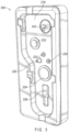
- FIGS. 2A and 2B illustrate examples of a disposable IV pump cassette 100 and corresponding pump cassette recess 200 of an interface module.
- Cassette 100 may comprise a pump cassette body 110 and a slider 170.
- Cassette 100 may include certain may include certain visual indicators related to operation aspects of the cassette and the infusion pump system in general.
- cassette may include identifiable images such as fluid drops indicating position of slider 170 for free-flow (flow stop valve 164 in an open position) and a patient figure proximal to outlet 114.
- cassette 100 may include lens area 173 for magnification of the fluid pathway within the pump cassette body 110.
- Lens area 173 may be disposed on the slider 170 or proximal to outlet 114 and/or an air-in-line detection feature. For example, during priming or propping a cassette, a user or caregiver may use lens area 173 to ensure that any visible air bubbles have been removed and fluid is flowing properly.
- one or more cassette-seated sensors may be disposed within the pump cassette recess 200 so as to inform central processing unit 12 that the cassette is locked or secured into place within the pump cassette recess 200 or seat.
- Slider 170 can be fixably and slidably engaged with pump cassette body 110 such that slider 170 may articulate longitudinally 191 with respect to pump cassette body 110, but will be constrained within range of sliding motion such that the slider remains coupled to the pump cassette body 110.
- Slider 170 may be formed from rigid plastic or polymer material having lubricating characteristics (e.g., incorporating silicon or polytetrafluoroethylene (PTFE) additives), and is clear or translucent in accordance with certain embodiments.
- slider 170 may be polycarbonate.
- Slider 170 includes a slider grip 172 or handle portion and a plurality of protrusions 174 or lugs that are configured to be releasably lockable with a plurality of slots 274 of the pump cassette recess 200 (e.g., L-shaped locking channels).
- cassette 100 can be self-latched into the pump cassette recess 200. Accordingly, a door or lever action is not required in order to retain the cassette 100 within the pump cassette recess 200.
- an inverse configuration may be desired, in which the pump cassette recess 200 would contain protrusions or lugs that would be configured to be releasably lockable with a corresponding slots located on the slider or rigid body.
- Pump cassette body 110 may extend depth (D) between 6 mm and 8 mm.
- Fluid pathway extension member 128 may further extend between 8 mm to 10 mm.
- slider grip 172 may extend between 10 mm to 14 mm from pump cassette body 110. It is to be appreciated that the process of cleaning of inlet recess 212, outlet recess 214, and pump cassette recess 200 is made efficient in the shallow recess configuration in accordance with certain embodiments should any fluid or debris accumulate within pump cassette recess 200.
- the shallow recess configuration of pump cassette recess 200, and associated longitudinal alignment of cassette 100 such that a smaller of volumetric dimensions of cassette 100 (e.g., depth being smaller than length and width in certain embodiments) further enables additional space for arrangement of mechanical couplings and operational interfaces and optimizes the overall space requirements of pump cassette recess 200 and infusion pump system in general.
- cassette 100 can be loaded directly into pump cassette recess 200.
- the direct loading of the cassette 100 will enable avoidance of sheer forces that might otherwise be applied to the sensors, alignment features, and other engaging interfaces of cassette-facing surface 216 of pump cassette recess 200 from interaction with the interface-facing side of pump cassette body 110 as it is loaded into pump cassette recess 200.
- pump cassette body 110 may comprise interface-facing frame portion 116 and slider-facing base portion 119 with membrane 117 disposed substantially therebetween (e.g., portions of membrane 117 may extend through some openings of frame portion 116).
- membrane 117 can be a compliant material co-molded to the frame portion 116 and sealingly engaged with base portion 119 for defining a fluid pathway through pump cassette body 110 from inlet 112 to outlet 114. Mating edges of frame portion 116 and base portion 119 may be connected by fusing, welding, gluing, or the like.
- Membrane 117 and base portion 119 may further define a plurality of other features, some of which may be accessed through openings in frame portion 116.
- Frame portion 116, membrane 117, and/or base portion 119 may define features in or along the fluid pathway, in accordance with certain embodiments.
- the fluid pathway may include features such as, but not limited to, upstream pressure dome 132 (e.g., an inlet-side compliant reservoir), inlet-side valve 122, pump chamber having pump chamber opening/access 125, outlet-side valve 124, downstream pressure dome 134 (e.g., an outlet-side compliant reservoir), fluid pathway extension member 128, and flow stop valve 164.
- Other features that are not in or along the fluid pathway, but are disposed on pump cassette body 110, may include positioning port 120 and slider stopper 151.
- fluid pathway extension member 128 may be formed from orthogonally extending portions of frame portion 116, membrane 117, and/or base portion 119.
- membrane 117 may be formed from a thermoplastic elastomer (TPE). Characteristics of certain TPEs can enable effective co-molding with other materials such as polycarbonate. Accordingly, in some embodiments, membrane 117 may be co-molded to frame portion 116 and striker 181 may be co-molded to a portion of membrane 117 defining a flow stop valve 164. However, in some embodiments, membrane 117 can be formed from silicon, a silicon-based compound, an elastomeric material suitably compliant for fluid flow, or the like.
- TPE thermoplastic elastomer
- interface-facing frame portion 116 and slider-facing base portion 119 may be formed from a rigid plastic such as, but not limited, to a polycarbonate. Additionally, the rigid plastic of frame portion 116 and base portion 119 may be clear or translucent. The material of membrane 117 (e.g., TPE or other compliant material) and rigid plastic slider 170 may also be clear or translucent, thereby allowing a user or caregiver to readily observe fluid passage through a substantial portion of the fluid pathway of pump cassette body 110. In some embodiments, the fluid pathway portion of pump cassette body 110 will be clear or translucent, and other portions will be frosted so as to direct a user or caregiver's attention to the fluid pathway.
- a rigid plastic such as, but not limited, to a polycarbonate.
- the rigid plastic of frame portion 116 and base portion 119 may be clear or translucent.
- the material of membrane 117 (e.g., TPE or other compliant material) and rigid plastic slider 170 may also be clear or translucent, thereby allowing a user or caregiver to readily observe fluid
- slider 170, base portion 119, and membrane 117 may be clear or translucent (or at least some portions along the fluid pathway), and the frame portion 116 may not be translucent.
- the frame portion 116 may be colored in a manner so as to contrast against a color or tint of the fluid expected to be used with cassette 100.
- a lens area 173 may be disposed on base portion 119 alternatively, or in addition to, lens area 173 disposed on slider 170.
- one or more fluid sensors may be disposed within sensor slot 228.
- the one or more fluid sensors disposed within sensor slot 228 can be ultrasonic sensors configured as an air-in-line detector, for example.
- extension member 128 may be disposed on pump cassette body 110 and positioned along the fluid pathway between downstream pressure dome 134 and flow stop valve 164. However, in some embodiments, extension member 128 can be positioned at other locations along the fluid pathway such as, but not limited to, between inlet 112 and upstream pressure dome 132. Additionally, in other embodiments, a plurality of extension members 128 with a plurality of corresponding sensor slots 228 may be positioned along a fluid pathway of pump cassette body 110.
- the positioning of the air-in-line sensor system is illustrated generally as part of multiple embodiments of a pump cassette and infusion pump system in FIGS. 2C , 3 , 4 and 5 .
- the purpose of the system is to detect air bubbles in the fluid flow of the IV infusion and to alert a clinician or user via an audio-visual cue or electronic means (such as an alert notice sent to a wireless device) when the volume of air passing through the system reaches or passes a predetermined threshold. It is also contemplated that the system could automatically stop the flow to the patient if an air bubble is detected, although the preferred method is to alert a clinician or user to the presence of an air bubble in the fluid flow.
- the system comprises two parts: a fitment and a sensor.
- the "fitment” portion of the air-in-line sensor (also referred to as the "fluid pathway extension member") is labeled as 128 while the “sensor slot” portion is labeled as 228.
- the specifics of the air-in-line sensor will be described in detail with respect to FIGS. 6A-13 using the reference numbers 128 for the fitment and 228 for the sensor slot.
- the positioning of the fitment 128 and corresponding sensor slot 228 can vary depending on the design of the pump cassette body 100 and the pump cassette recess 200 into which it is inserted.
- FIG. 4 shows the fitment 128 positioned on the lower portion of the pump cassette body 100
- FIG. 2B shows the corresponding sensor slot 228 on the lower portion of the pump cassette recess. It should be understood that the positioning of the fitment 128 and corresponding sensor slot 228 can vary depending on the design of the pump cassette body 100 and pump cassette recess 200 and the illustrated embodiments should not be construed to limit the claims.
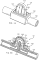
- FIGS. 6A , 9B , 11 and 12 illustrate the fitment 128 positioned on a generic IV line 1300, but in operation, the fitment 128 is formed as an integral part of the pump cassette body 100 as shown in FIGS. 4 and 13 for example.
- the fitment 128 includes a base portion 1302 integrally molded into the hard plastic housing 1314 that extends upwards from the pump cassette body 100.
- the base portion 1302 also includes a flow director vane 1304 integrally molded into the housing of the pump cassette body 100 and extending upwardly from the base portion 1302.
- the flow director vane 1304 may be hollow, as illustrated in FIG. 10 , or solid, as illustrated in FIG. 9 .
- the fitment 128 also includes an elastomeric member 1306 with soft sides and a hollow interior creating a fluid flow path 1308 in conjunction with the flow director vane 1304 as shown in FIG. 6B .
- the elastomeric member 1306 also includes tapered outside walls 1310.
- FIG. 17 illustrates an exploded view of the fitment 128.
- FIGS. 10 , 10A, 10B and 10C a specific embodiment of the internal structure of the air-in-line fitment is illustrated.
- the shape of the flow director vane 1304 in conjunction with the interior shape of the elastomeric member 1306 creates a fluid flow path 1308 that is optimized to improve fluid flow through the sensing area 1322, which is the area between the top 1330 of the flow director vane 1304 and the curved inside wall 1332 of the elastomeric member 1306.
- the positioning and shape of the flow director vane 1304 is important because the intrusion of the hard plastic of the flow director vane 1304 into the path of the sensing area 1322 can short circuit the acoustic beam used in the sensor.
- the sensing area 1322 is illustrated in cross-section in FIG. 9A .
- the flow director vane 1304 extends into the elastomeric member 1306 such that the angled flow regions 1324 on the sides 1328 of the flow director vane 1304 are thinner than the portion of the fluid flow path 1308 within the sensing area 1322 above the top 1330 of the flow director vane 1304.
- This wider portion of the fluid flow path 1308 is a result of the interior of the elastomeric member 1306 having straight internal walls 1334 that extend in a straight line above the top 1330 of the flow director vane 1304 before the curvature 1332 of the elastomeric member 1306 begins.
- the curvature of the top 1330 of the flow director vane 1304 substantially matches the inside curvature 1332 of the elastomeric member 1306 as shown in FIG. 10 .
- FIGS. 10A, 10B and 10C dimensions of an exemplary embodiment of the fluid flow path 1308 of the fitment 128 are illustrated. It should be noted that these dimensions are exemplary only, and are not meant to limit the disclosure.
- the height H at the highest point of the sensing area 1322 of the fluid flow path 1308 from the top of the flow director vane 1304 to the inside curved wall 1332 of the elastomeric member is between about .120"-3.05".
- the flow director vane 1304 has side walls 1328 angled at approximately 14° between the side walls 1328. This creates a tapered flow path 1308 with upstream 1352 and downstream 1354 portions on either side of the flow director vane 1304. In an exemplary embodiment, as shown in FIG.
- the angle of the side walls 1328 of the flow director vane 1304 creates distances between the side walls 1328 of the flow director vane 1304 and the side walls 1356 of the elastomeric member 1306 of between about .047"-1.19" in a first section 1358 of the upstream portion 1352, between about .047"-1.20" in a second section 1360 of the upstream portion 1352, between about .060"-1.52” in a third section 1362 of the upstream portion 1352, between about .097"-2.47” in a fourth section 1364 of the upstream portion 1352, and between about.115"-2.93" in a fifth section 1366 of the upstream portion 1352 .
- the angle of the side walls 1328 of the flow director vane 1304 creates distances between the side walls 1328 of the flow director vane 1304 and the side walls 1356 of the elastomeric member 1306 of between about.115"-2.93" in a first section 1374 of the downstream portion 1354, between about .097"-2.47” in a second section 1376 of the downstream portion 1354, between about .060"-1.52" in a third section 1378 of the downstream portion 1354, between about .047"-1.20” in a fourth section 1380 of the downstream portion 1354, and between about .047"-1.19” in a fifth section 1382 of the downstream portion 1354.
- FIG. 10C illustrates a cross-sectional view of FIG. 10B along line G-G of FIG. 10A .
- the flow director vane 1304 is between about .072"-1.84" wide in cross-section with substantially vertical walls 1370.
- the front and back walls 1368 of the elastomeric member 1306 in this area are situated at an angle of about 12° between them, resulting in a width of between about .047"-1.20" at the thinnest area of the top 1372 of the flow path 1308.
- FIG. 10B illustrates a three-dimensional perspective view of the specialized flow path of this embodiment of the fitment 128.
- the tapered flow path 1308 that results from these variances in distances creates a fluid flow path 1308 with its largest volume at the top 1372 of the flow path 1308 that tapers down to a smaller volume as the flow path 1308 moves away from the top 1372 of the flow path 1308 into the upstream 1352 and downstream 1354 portions. This creates a total enclosed volume within the sensing area 1322 of about 0.000876in 3 .
- the elastomeric member 1306 is co-molded to the hard plastic housing 1314 of the pump cassette body 100 and may include a cored feature 131.2 as shown in FIG. 8 to provide secure attachment of the elastomeric member 1306 to the hard plastic housing 1314.
- the elastomeric member 1306 may include an extension 1350 that fits into the cored feature 1312.
- the hard plastic housing 1314 is shaped to match the outer curve of the elastomeric member 1306 to ensure that it maintains its interference fit within the hard plastic housing 1314.
- the elastomeric member 1306 of the fitment 128 is constructed of a malleable material such as silicone or thermoplastic elastomer (TPE).
- TPE thermoplastic elastomer
- An exemplary material is an RTV silicone with an approximate shore hardness of 40. Referring to FIG. 10 , the use of such material in conjunction with wedge shape formed by the tapered outside walls 1310 allows the fitment 128 to slide into the sensor slot 228 and securely maintain this position due to the interference fit between the inner walls 1316 of the sensor slot 228 and the outer walls 1310 of the fitment 128 as shown in FIG. 12 . These tapered outside walls 1310 also maintain a proper acoustic coupling with the sensor as described below. The elastomeric material also resists creep, thus maintaining the proper position of the fluid flow path 1308.
- the elastomeric material allows easy insertion of the pump cassette body 100 into the pump cassette recess 200 while ensuring proper positioning.
- the incorporation of the fitment 128 into the pump cassette body 100 provides automatic insertion of the fitment 128 into the sensor slot 228 due to the alignment features present on the pump cassette body 100 and pump cassette recess 200, thus eliminating mis-loading which can lead to false alarms.
- the second portion of the air-in-line sensing system is the sensor.
- the sensor may be a piezo-electric transducer pair comprising a transmitter 1318 and receiver 1320 positioned on either side of the sensor slot 228 such that when the fitment 128 is inserted into the sensor slot 228, the transmitter 1318 and receiver 1320 are on opposite sides of the fitment 128.
- Exemplary sensors are an Introtek 8V139 or a PiezoTechnologies 200015 although other sensors known in the art are contemplated.
- the sensors are preferably able to detect the air volume within the fluid flow path 1308 with an accuracy within about ⁇ 20% for air-in-line alarm limits above 100 ⁇ L or within ⁇ 20 ⁇ L for air-in-line limits equal to or below 100 ⁇ L. Additionally, the sensor algorithm is optimized to the fitment 128 to improve its accuracy. When the fitment 128 is in place in the sensor slot 228 and positioned between the sensor's transmitter 1318 and receiver 1320, the fluid flow path 1308 preferably takes up more than 50% of the sensing area 1322 between the transmitter 1318 and receiver 1320.
- the specialized horseshoe shape of the fluid flow path 1308 within the fitment 128 has multiple advantages.
- This convergent-divergent design of the fluid flow path 1308 within the fitment 128 maintains a constant fluid velocity as the fluid travels through the sensing area 1322 of the fitment 128. It also reduces turbulence and results in an absence of large velocity gradients in the sensing area 1322 which improves the monitoring capability of the sensor.
- the angled fluid flow path 1308 reduces pressure loss and eliminates areas of fluid stagnation that can result in bubbles "sticking" within the fluid flow path 1308.
- the design of the fluid flow path 1308 creates angled flow regions 1324 that reduce the incidence of fluid getting trapped in the fitment 128. This is required as stationary fluid may prevent the system from sensing that the IV container is empty.
- ultrasonic energy in the form of an acoustic beam 1326 is generated by the sensor's transmitter 1318 and directed through the sensing area 1322 of the fluid flow path 1308 of the fitment 128 towards the sensor's receiver 1320. Air bubbles flowing through the sensing area 1322 of the fluid flow path 1308 of the fitment 128 pass through the acoustic beam 1326 of the sensor and block the acoustic energy.
- Blockage is detected by the sensor's receiver 1320 and electronic components in the sensor monitor this condition and provide an electrical signal.
- the size of the air bubble can be determined by measuring the time interval of the signal, which indicates the start and end of the air bubble as it passes through the acoustic beam 1326. In operation, if the air bubble exceeds a certain size, the sensor sends a signal to a controller signaling the system to stop the pump operation and to signal the user by way of an audio-visual signal that an air bubble has been sensed within the fluid flow.
- infusion pump systems disclosed herein may include an electronic system with one or more processors embedded therein or coupled thereto.
- Such an electronic system may include various types of computer readable media and interfaces for various other types of computer readable media.
- Electronic system may include a bus, processing unit(s), a system memory, a read-only memory (ROM), a permanent storage device, an input device interface, an output device interface, and a network interface, for example.
- Bus may collectively represent all system, peripheral, and chipset buses that communicatively connect the numerous internal devices of electronic system of an infusion pump system.
- bus may communicatively connect processing unit(s) with ROM, system memory, and permanent storage device. From these various memory units, processing unit(s) may retrieve instructions to execute and data to process in order to execute various processes.
- the processing unit(s) can be a single processor or a multi-core processor in different implementations.
- the phrase "at least one of” preceding a series of items, with the term “or” to separate any of the items, modifies the list as a whole, rather than each item of the list.
- the phrase "at least one of” does not require selection of at least one item; rather, the phrase allows a meaning that includes at least one of any one of the items, and/or at least one of any combination of the items, and/or at least one of each of the items.
- the phrase “at least one of A, B, or C” may refer to: only A, only B, or only C; or any combination of A, B, and C.
- a phrase such as an "aspect” does not imply that such aspect is essential to the subject technology or that such aspect applies to all configurations of the subject technology.
- a disclosure relating to an aspect may apply to all configurations, or one or more configurations.
- An aspect may provide one or more examples.
- a phrase such as an aspect may refer to one or more aspects and vice versa.
- a phrase such as an "embodiment” does not imply that such embodiment is essential to the subject technology or that such embodiment applies to all configurations of the subject technology.
- a disclosure relating to an embodiment may apply to all embodiments, or one or more embodiments.
- An embodiment may provide one or more examples.
- a phrase such an embodiment may refer to one or more embodiments and vice versa.
- a phrase such as a "configuration” does not imply that such configuration is essential to the subject technology or that such configuration applies to all configurations of the subject technology.
- a disclosure relating to a configuration may apply to all configurations, or one or more configurations.
- a configuration may provide one or more examples.
- a phrase such a configuration may refer to one or more configurations and vice versa.
Landscapes
- Health & Medical Sciences (AREA)
- Vascular Medicine (AREA)
- Engineering & Computer Science (AREA)
- Anesthesiology (AREA)
- Biomedical Technology (AREA)
- Heart & Thoracic Surgery (AREA)
- Hematology (AREA)
- Life Sciences & Earth Sciences (AREA)
- Animal Behavior & Ethology (AREA)
- General Health & Medical Sciences (AREA)
- Public Health (AREA)
- Veterinary Medicine (AREA)
- Emergency Medicine (AREA)
- Infusion, Injection, And Reservoir Apparatuses (AREA)
Claims (15)
- Pumpenkassettenkörper (110) zum Erfassen von Luftblasen in einem Fluidpfad, wobei der Pumpenkassettenkörper (110) aufweist:einen aufragenden Strömungsleitflügel (1304);ein Einpassteil (128), das in den Pumpenkassettenkörper (110) einstückig eingeformt ist, wobei das Einpassteil (128) aufweist:einen Sockel (1302), der in den Pumpenkassettenkörper (110) einstückig eingeformt ist;ein Elastomerelement (1306), das am Sockel (1302) angebracht ist; undein Gehäuse (1314), welches das Elastomerelement (1306) zumindest teilweise umgibt,dadurch gekennzeichnet, dass,der Strömungsleitflügel (1304) und das Elastomerelement (1306) einen sich verjüngenden Kanal bilden, der dafür ausgelegt ist, bei einer Fluidströmung durch den Pumpenkassettenkörper (110) entlang einer Fluidströmungsrichtung vor einem Erfassungsbereich (1322) an einer Spitze des Strömungsleitflügels (1304) einen auseinanderlaufenden Querschnitt einer Fluidströmungsbahn (1308) bereitzustellen und entlang der Fluidströmungsrichtung nach dem Erfassungsbereich (1322) einen zusammenlaufenden Querschnitt der Fluidströmungsbahn (1308) bereitzustellen.
- Pumpenkassettenkörper (110) nach Anspruch 1, wobei der Pumpenkassettenkörper (110) abnehmbar an einer Pumpenkassettenaussparung (200) mit einer darin ausgebildeten Nut (228) angebracht werden kann, wobei die Nut (228) im Wesentlichen den Abmessungen des Einpassteils (128) entspricht und gegenüberliegende Wände (1316) hat; und
einen akustischen Sensor, der innerhalb der Pumpenkassettenaussparung (200) vorgesehen ist, wobei der akustische Sensor einen Sender (1318) und einen Empfänger (1320) aufweist, wobei der Sender (1318) und der Empfänger (1320) hinter entgegengesetzten, gegenüberliegenden Wänden (1316) der Nut (228) vorgesehen ist. - Pumpenkassettenkörper (110) nach Anspruch 1, wobei der Strömungsleitflügel (1304) schräge Wände (1328) umfasst und innerhalb eines hohlen Innenbereichs des Elastomerelements (1306) vorgesehen ist, um darin eine im Wesentlichen U-förmige Fluidströmungsbahn mit sich verjüngenden Wänden zu erzeugen.
- Pumpenkassettenkörper (110) nach Anspruch 3, wobei das Elastomerelement (1306) darüber hinaus sich verjüngende Außenwände (1310) aufweist.
- Pumpenkassettenkörper (110) nach Anspruch 4, wobei das Elastomerelement (1306) darüber hinaus sich verjüngende Innenwände aufweist.
- Pumpenkassettenkörper (110) nach Anspruch 5, wobei die Fluidströmungsbahn (1308) eine Höhe (H) zwischen ca. 0,120" und 3,05" an ihrem höchsten Punkt hat.
- Pumpenkassettenkörper (110) nach Anspruch 5, wobei die Fluidströmungsbahn (1308) einen stromaufwärtigen Abschnitt (1352) und einen stromabwärtigen Abschnitt (1354) hat, der stromaufwärtige Abschnitt (1352) am höchsten Punkt der Fluidströmungsbahn (1308) auf den stromabwärtigen Abschnitt (1354) trifft, der stromaufwärtige Abschnitt (1352) eine Höhe zwischen ca. 0,047" und 1,19" in einem ersten Teilstück des stromaufwärtigen Abschnitts (1352) hat, eine Höhe zwischen ca. 0,047" und 1,20" in einem zweiten Teilstück des stromaufwärtigen Abschnitts (1352) hat, eine Höhe zwischen ca. 0,060" und 1,52" in einem dritten Teilstück des stromaufwärtigen Abschnitts (1352) hat, eine Höhe zwischen ca. 0,097" und 2,47" in einem vierten Teilstück des stromaufwärtigen Abschnitts (1352) hat, und eine Höhe zwischen ca. 0,115" und 2,93" in einem fünften Teilstück des stromaufwärtigen Abschnitts (1352) hat.
- Pumpenkassettenkörper (110) nach Anspruch 7, wobei der stromabwärtige Abschnitt (1354) eine Höhe zwischen ca.0,115" und 2,93" in einem ersten Teilstück des stromabwärtigen Abschnitts (1354) hat, eine Höhe zwischen ca.0,097" und 2,47" in einem zweiten Teilstück des stromabwärtigen Abschnitts (1354) hat, eine Höhe zwischen ca.0,060" und 1,52" in einem dritten Teilstück des stromabwärtigen Abschnitts (1354) hat, eine Höhe zwischen ca.0,047" und 1,20" in einem vierten Teilstück des stromabwärtigen Abschnitts (1354) hat, und eine Höhe zwischen ca. 0,047" und 1,19" in einem fünften Teilstück des stromabwärtigen Abschnitts (1354) hat.
- Pumpenkassettenkörper (110) nach Anspruch 1, wobei das Elastomerelement (1306) keilförmig ist und sein breitester Abschnitt breiter als die Sensornut (228) ist.
- Pumpenkassettenkörper (110) nach Anspruch 1, wobei das Gehäuse (1314), welches das Elastomerelement (1306) umgibt, bogenförmig ist.
- Pumpenkassettenkörper (110) nach Anspruch 10, wobei das Gehäuse (1314) darüber hinaus eine Öffnung (1312) und das Elastomerelement (1306) darüber hinaus eine Verlängerung (1350) aufweist, die im Wesentlichen in die Öffnung (1312) des Gehäuses (1314) hineinpasst, welches das Elastomerelement (1306) umgibt.
- Pumpenkassettenkörper (110) nach Anspruch 1, wobei das Elastomerelement (1306) ein thermoplastisches Elastomer ist.
- System (11) zum Erfassen von Luftblasen in einem Fluidpfad, wobei das System aufweist:eine zentrale Verarbeitungseinheit (13);einen Bildschirm (15);ein Dateneingabemerkmal (17); undden Pumpenkassettenkörper (110) nach einem der Ansprüche 1-12.
- System (11) zum Erfassen von Luftblasen in einem Fluidpfad, wobei das System aufweist:eine zentrale Verarbeitungseinheit (13);einen Bildschirm (15);ein Dateneingabemerkmal (17); undden Pumpenkassettenkörper (110) nach Anspruch 2, wobei durch das Einführen des Einpassteils (128) in die Nut (228) eine Druckbelastung zwischen dem Einpassteil (128) und den Wänden der Nut (228) erzeugt wird.
- System nach Anspruch 14, wobei das Elastomerelement (1306) darüber hinaus eine Verlängerung (1350) und das Gehäuse (1314) darüber hinaus eine Nut (1312) aufweist, die im Wesentlichen mit der Verlängerung (1350) zusammenpasst.
Applications Claiming Priority (2)
| Application Number | Priority Date | Filing Date | Title |
|---|---|---|---|
| US14/721,928 US10300219B2 (en) | 2015-05-26 | 2015-05-26 | Air in-line sensing system for IV infusion lines |
| PCT/US2016/012731 WO2016190904A1 (en) | 2015-05-26 | 2016-01-08 | Air in-line sensing system for iv infusion lines |
Publications (3)
| Publication Number | Publication Date |
|---|---|
| EP3302625A1 EP3302625A1 (de) | 2018-04-11 |
| EP3302625A4 EP3302625A4 (de) | 2019-01-16 |
| EP3302625B1 true EP3302625B1 (de) | 2024-04-03 |
Family
ID=57393597
Family Applications (1)
| Application Number | Title | Priority Date | Filing Date |
|---|---|---|---|
| EP16800405.9A Active EP3302625B1 (de) | 2015-05-26 | 2016-01-08 | System zur erfassung von luft in der leitung für iv-infusionsleitungen |
Country Status (6)
| Country | Link |
|---|---|
| US (2) | US10300219B2 (de) |
| EP (1) | EP3302625B1 (de) |
| CN (2) | CN206621618U (de) |
| AU (1) | AU2016267972B2 (de) |
| CA (1) | CA2986012C (de) |
| WO (1) | WO2016190904A1 (de) |
Families Citing this family (15)
| Publication number | Priority date | Publication date | Assignee | Title |
|---|---|---|---|---|
| US10245373B2 (en) | 2014-12-01 | 2019-04-02 | Carefusion 2200, Inc. | Pump cassettes with positioning feature and infusion pump systems |
| US10293102B2 (en) | 2014-12-01 | 2019-05-21 | Carefusion 2200, Inc. | Pump cassettes with piston and infusion pump systems |
| US10363360B2 (en) | 2014-12-01 | 2019-07-30 | Carefusion 2200, Inc. | Pump cassettes with slider and infusion pump systems |
| US10376639B2 (en) | 2014-12-01 | 2019-08-13 | Carefusion 2200, Inc. | Valving system for infusion cassette |
| AU201810653S (en) * | 2017-12-06 | 2018-05-04 | Nutricia Nv | Control panels with displays for feeding devices [medical] |
| USD917045S1 (en) | 2018-08-16 | 2021-04-20 | Deka Products Limited Partnership | Slide clamp |
| USD1004412S1 (en) | 2019-08-16 | 2023-11-14 | Deka Products Limited Partnership | Slide clamp assembly |
| KR20240113619A (ko) | 2020-02-21 | 2024-07-22 | 바이엘 헬쓰케어 엘엘씨 | 의료 유체 전달용 유체 경로 커넥터 |
| PH12022552286A1 (en) | 2020-02-28 | 2023-12-18 | Bayer Healthcare Llc | Fluid mixing set |
| WO2021188460A1 (en) | 2020-03-16 | 2021-09-23 | Bayer Healthcare Llc | Stopcock apparatus for angiography injector fluid paths |
| PH12022553506A1 (en) | 2020-06-18 | 2024-04-29 | Bayer Healthcare Llc | In-line air bubble suspension apparatus for angiography injector fluid paths |
| AU2021326454A1 (en) | 2020-08-11 | 2023-03-02 | Bayer Healthcare Llc | Features for angiography syringe |
| PH12023551507A1 (en) * | 2020-12-01 | 2024-05-13 | Bayer Healthcare Llc | Cassette for retention of fluid path components for fluid injector system |
| CN117500538A (zh) | 2021-06-17 | 2024-02-02 | 拜耳医药保健有限责任公司 | 用于检测流体注入器装置的管路中的流体类型的系统和方法 |
| USD1115053S1 (en) * | 2023-11-09 | 2026-02-24 | Boston Scientific Scimed, Inc. | Fluid cassette for a fluid management system |
Family Cites Families (12)
| Publication number | Priority date | Publication date | Assignee | Title |
|---|---|---|---|---|
| US4303376A (en) * | 1979-07-09 | 1981-12-01 | Baxter Travenol Laboratories, Inc. | Flow metering cassette and controller |
| GB8424101D0 (en) | 1984-09-24 | 1984-10-31 | Vi Tal Hospital Products Ltd | Air-in-line detector |
| DE3530747A1 (de) | 1985-08-28 | 1987-03-05 | Stoeckert Instr Gmbh | Ultraschallsensor |
| US4842584A (en) * | 1987-05-01 | 1989-06-27 | Abbott Laboratories | Disposable fluid infusion pumping chamber cassette and drive mechanism thereof |
| US5641892A (en) * | 1995-06-07 | 1997-06-24 | Deka Products Limited Partnership | Intravenous-line air-detection system |
| US5382232A (en) | 1992-03-13 | 1995-01-17 | Ivac Corporation | Infusion system with air-in-line clear function |
| US5603613A (en) * | 1994-09-12 | 1997-02-18 | Ivac Corp | Fluid delivery system having an air bubble ejector |
| US6616633B1 (en) | 1997-09-19 | 2003-09-09 | Alaris Medical Systems, Inc. | Apparatus and method for air-in-line detection |
| US6489896B1 (en) | 2000-11-03 | 2002-12-03 | Baxter International Inc. | Air in-line sensor for ambulatory drug infusion pump |
| US6494694B2 (en) | 2001-04-25 | 2002-12-17 | Abbott Laboratories | Disposable infusion cassette with low air bubble retention and improved valves |
| DE10224750A1 (de) | 2002-06-04 | 2003-12-24 | Fresenius Medical Care De Gmbh | Vorrichtung zur Behandlung einer medizinischen Flüssigkeit |
| EP1403519A1 (de) | 2002-09-27 | 2004-03-31 | Novo Nordisk A/S | Membranpumpe mit dehnbarer Pumpenmembran |
-
2015
- 2015-05-26 US US14/721,928 patent/US10300219B2/en active Active
-
2016
- 2016-01-08 CA CA2986012A patent/CA2986012C/en active Active
- 2016-01-08 EP EP16800405.9A patent/EP3302625B1/de active Active
- 2016-01-08 WO PCT/US2016/012731 patent/WO2016190904A1/en not_active Ceased
- 2016-01-08 AU AU2016267972A patent/AU2016267972B2/en active Active
- 2016-01-25 CN CN201621401113.3U patent/CN206621618U/zh not_active Expired - Lifetime
- 2016-01-25 CN CN201620070494.5U patent/CN205796164U/zh not_active Expired - Lifetime
-
2019
- 2019-05-07 US US16/405,865 patent/US11097069B2/en active Active
Also Published As
| Publication number | Publication date |
|---|---|
| CN205796164U (zh) | 2016-12-14 |
| WO2016190904A1 (en) | 2016-12-01 |
| US20160346484A1 (en) | 2016-12-01 |
| EP3302625A4 (de) | 2019-01-16 |
| US20190262550A1 (en) | 2019-08-29 |
| US11097069B2 (en) | 2021-08-24 |
| US10300219B2 (en) | 2019-05-28 |
| EP3302625A1 (de) | 2018-04-11 |
| AU2016267972B2 (en) | 2020-11-19 |
| CA2986012C (en) | 2023-03-07 |
| CN206621618U (zh) | 2017-11-10 |
| AU2016267972A1 (en) | 2017-11-23 |
| CA2986012A1 (en) | 2016-12-01 |
Similar Documents
| Publication | Publication Date | Title |
|---|---|---|
| US11097069B2 (en) | Air in-line sensing system for IV infusion lines | |
| US12403242B2 (en) | Pump systems with positioning features | |
| US10363360B2 (en) | Pump cassettes with slider and infusion pump systems | |
| CN106573095B (zh) | 用于体外血液透析机的压力输出装置 | |
| EP1699509B1 (de) | Nachweis von leeren behältern mit behälter-seitendruckmessung | |
| US20160151564A1 (en) | Pump cassettes with piston and infusion pump systems | |
| US20240261497A1 (en) | Infusion system with sensor system having reduced compliance sensitivity | |
| CN121102634A (zh) | 注射软管组件、高压注射系统及注射调控方法 | |
| CA3227669A1 (en) | Infusion system with sensor system having reduced compliance sensitivity |
Legal Events
| Date | Code | Title | Description |
|---|---|---|---|
| STAA | Information on the status of an ep patent application or granted ep patent |
Free format text: STATUS: THE INTERNATIONAL PUBLICATION HAS BEEN MADE |
|
| PUAI | Public reference made under article 153(3) epc to a published international application that has entered the european phase |
Free format text: ORIGINAL CODE: 0009012 |
|
| STAA | Information on the status of an ep patent application or granted ep patent |
Free format text: STATUS: REQUEST FOR EXAMINATION WAS MADE |
|
| 17P | Request for examination filed |
Effective date: 20171113 |
|
| AK | Designated contracting states |
Kind code of ref document: A1 Designated state(s): AL AT BE BG CH CY CZ DE DK EE ES FI FR GB GR HR HU IE IS IT LI LT LU LV MC MK MT NL NO PL PT RO RS SE SI SK SM TR |
|
| AX | Request for extension of the european patent |
Extension state: BA ME |
|
| DAV | Request for validation of the european patent (deleted) | ||
| DAX | Request for extension of the european patent (deleted) | ||
| A4 | Supplementary search report drawn up and despatched |
Effective date: 20181219 |
|
| RIC1 | Information provided on ipc code assigned before grant |
Ipc: A61M 5/168 20060101ALI20181213BHEP Ipc: A61M 5/172 20060101AFI20181213BHEP Ipc: A61M 5/142 20060101ALI20181213BHEP Ipc: A61M 5/36 20060101ALI20181213BHEP |
|
| GRAP | Despatch of communication of intention to grant a patent |
Free format text: ORIGINAL CODE: EPIDOSNIGR1 |
|
| STAA | Information on the status of an ep patent application or granted ep patent |
Free format text: STATUS: GRANT OF PATENT IS INTENDED |
|
| INTG | Intention to grant announced |
Effective date: 20231030 |
|
| GRAS | Grant fee paid |
Free format text: ORIGINAL CODE: EPIDOSNIGR3 |
|
| GRAA | (expected) grant |
Free format text: ORIGINAL CODE: 0009210 |
|
| STAA | Information on the status of an ep patent application or granted ep patent |
Free format text: STATUS: THE PATENT HAS BEEN GRANTED |
|
| P01 | Opt-out of the competence of the unified patent court (upc) registered |
Effective date: 20240125 |
|
| AK | Designated contracting states |
Kind code of ref document: B1 Designated state(s): AL AT BE BG CH CY CZ DE DK EE ES FI FR GB GR HR HU IE IS IT LI LT LU LV MC MK MT NL NO PL PT RO RS SE SI SK SM TR |
|
| REG | Reference to a national code |
Ref country code: GB Ref legal event code: FG4D |
|
| REG | Reference to a national code |
Ref country code: CH Ref legal event code: EP |
|
| REG | Reference to a national code |
Ref country code: IE Ref legal event code: FG4D |
|
| REG | Reference to a national code |
Ref country code: DE Ref legal event code: R096 Ref document number: 602016086697 Country of ref document: DE |
|
| REG | Reference to a national code |
Ref country code: LT Ref legal event code: MG9D |
|
| REG | Reference to a national code |
Ref country code: NL Ref legal event code: MP Effective date: 20240403 |
|
| REG | Reference to a national code |
Ref country code: AT Ref legal event code: MK05 Ref document number: 1671551 Country of ref document: AT Kind code of ref document: T Effective date: 20240403 |
|
| PG25 | Lapsed in a contracting state [announced via postgrant information from national office to epo] |
Ref country code: NL Free format text: LAPSE BECAUSE OF FAILURE TO SUBMIT A TRANSLATION OF THE DESCRIPTION OR TO PAY THE FEE WITHIN THE PRESCRIBED TIME-LIMIT Effective date: 20240403 |
|
| PG25 | Lapsed in a contracting state [announced via postgrant information from national office to epo] |
Ref country code: NL Free format text: LAPSE BECAUSE OF FAILURE TO SUBMIT A TRANSLATION OF THE DESCRIPTION OR TO PAY THE FEE WITHIN THE PRESCRIBED TIME-LIMIT Effective date: 20240403 |
|
| PG25 | Lapsed in a contracting state [announced via postgrant information from national office to epo] |
Ref country code: IS Free format text: LAPSE BECAUSE OF FAILURE TO SUBMIT A TRANSLATION OF THE DESCRIPTION OR TO PAY THE FEE WITHIN THE PRESCRIBED TIME-LIMIT Effective date: 20240803 |
|
| PG25 | Lapsed in a contracting state [announced via postgrant information from national office to epo] |
Ref country code: BG Free format text: LAPSE BECAUSE OF FAILURE TO SUBMIT A TRANSLATION OF THE DESCRIPTION OR TO PAY THE FEE WITHIN THE PRESCRIBED TIME-LIMIT Effective date: 20240403 |
|
| PG25 | Lapsed in a contracting state [announced via postgrant information from national office to epo] |
Ref country code: FI Free format text: LAPSE BECAUSE OF FAILURE TO SUBMIT A TRANSLATION OF THE DESCRIPTION OR TO PAY THE FEE WITHIN THE PRESCRIBED TIME-LIMIT Effective date: 20240403 Ref country code: HR Free format text: LAPSE BECAUSE OF FAILURE TO SUBMIT A TRANSLATION OF THE DESCRIPTION OR TO PAY THE FEE WITHIN THE PRESCRIBED TIME-LIMIT Effective date: 20240403 |
|
| PG25 | Lapsed in a contracting state [announced via postgrant information from national office to epo] |
Ref country code: GR Free format text: LAPSE BECAUSE OF FAILURE TO SUBMIT A TRANSLATION OF THE DESCRIPTION OR TO PAY THE FEE WITHIN THE PRESCRIBED TIME-LIMIT Effective date: 20240704 |
|
| PG25 | Lapsed in a contracting state [announced via postgrant information from national office to epo] |
Ref country code: PT Free format text: LAPSE BECAUSE OF FAILURE TO SUBMIT A TRANSLATION OF THE DESCRIPTION OR TO PAY THE FEE WITHIN THE PRESCRIBED TIME-LIMIT Effective date: 20240805 |
|
| PG25 | Lapsed in a contracting state [announced via postgrant information from national office to epo] |
Ref country code: ES Free format text: LAPSE BECAUSE OF FAILURE TO SUBMIT A TRANSLATION OF THE DESCRIPTION OR TO PAY THE FEE WITHIN THE PRESCRIBED TIME-LIMIT Effective date: 20240403 |
|
| PG25 | Lapsed in a contracting state [announced via postgrant information from national office to epo] |
Ref country code: CZ Free format text: LAPSE BECAUSE OF FAILURE TO SUBMIT A TRANSLATION OF THE DESCRIPTION OR TO PAY THE FEE WITHIN THE PRESCRIBED TIME-LIMIT Effective date: 20240403 |
|
| PG25 | Lapsed in a contracting state [announced via postgrant information from national office to epo] |
Ref country code: AT Free format text: LAPSE BECAUSE OF FAILURE TO SUBMIT A TRANSLATION OF THE DESCRIPTION OR TO PAY THE FEE WITHIN THE PRESCRIBED TIME-LIMIT Effective date: 20240403 |
|
| PG25 | Lapsed in a contracting state [announced via postgrant information from national office to epo] |
Ref country code: PL Free format text: LAPSE BECAUSE OF FAILURE TO SUBMIT A TRANSLATION OF THE DESCRIPTION OR TO PAY THE FEE WITHIN THE PRESCRIBED TIME-LIMIT Effective date: 20240403 |
|
| PG25 | Lapsed in a contracting state [announced via postgrant information from national office to epo] |
Ref country code: LV Free format text: LAPSE BECAUSE OF FAILURE TO SUBMIT A TRANSLATION OF THE DESCRIPTION OR TO PAY THE FEE WITHIN THE PRESCRIBED TIME-LIMIT Effective date: 20240403 |
|
| PG25 | Lapsed in a contracting state [announced via postgrant information from national office to epo] |
Ref country code: PT Free format text: LAPSE BECAUSE OF FAILURE TO SUBMIT A TRANSLATION OF THE DESCRIPTION OR TO PAY THE FEE WITHIN THE PRESCRIBED TIME-LIMIT Effective date: 20240805 Ref country code: PL Free format text: LAPSE BECAUSE OF FAILURE TO SUBMIT A TRANSLATION OF THE DESCRIPTION OR TO PAY THE FEE WITHIN THE PRESCRIBED TIME-LIMIT Effective date: 20240403 Ref country code: NO Free format text: LAPSE BECAUSE OF FAILURE TO SUBMIT A TRANSLATION OF THE DESCRIPTION OR TO PAY THE FEE WITHIN THE PRESCRIBED TIME-LIMIT Effective date: 20240703 Ref country code: LV Free format text: LAPSE BECAUSE OF FAILURE TO SUBMIT A TRANSLATION OF THE DESCRIPTION OR TO PAY THE FEE WITHIN THE PRESCRIBED TIME-LIMIT Effective date: 20240403 Ref country code: IS Free format text: LAPSE BECAUSE OF FAILURE TO SUBMIT A TRANSLATION OF THE DESCRIPTION OR TO PAY THE FEE WITHIN THE PRESCRIBED TIME-LIMIT Effective date: 20240803 Ref country code: HR Free format text: LAPSE BECAUSE OF FAILURE TO SUBMIT A TRANSLATION OF THE DESCRIPTION OR TO PAY THE FEE WITHIN THE PRESCRIBED TIME-LIMIT Effective date: 20240403 Ref country code: GR Free format text: LAPSE BECAUSE OF FAILURE TO SUBMIT A TRANSLATION OF THE DESCRIPTION OR TO PAY THE FEE WITHIN THE PRESCRIBED TIME-LIMIT Effective date: 20240704 Ref country code: FI Free format text: LAPSE BECAUSE OF FAILURE TO SUBMIT A TRANSLATION OF THE DESCRIPTION OR TO PAY THE FEE WITHIN THE PRESCRIBED TIME-LIMIT Effective date: 20240403 Ref country code: ES Free format text: LAPSE BECAUSE OF FAILURE TO SUBMIT A TRANSLATION OF THE DESCRIPTION OR TO PAY THE FEE WITHIN THE PRESCRIBED TIME-LIMIT Effective date: 20240403 Ref country code: CZ Free format text: LAPSE BECAUSE OF FAILURE TO SUBMIT A TRANSLATION OF THE DESCRIPTION OR TO PAY THE FEE WITHIN THE PRESCRIBED TIME-LIMIT Effective date: 20240403 Ref country code: BG Free format text: LAPSE BECAUSE OF FAILURE TO SUBMIT A TRANSLATION OF THE DESCRIPTION OR TO PAY THE FEE WITHIN THE PRESCRIBED TIME-LIMIT Effective date: 20240403 Ref country code: AT Free format text: LAPSE BECAUSE OF FAILURE TO SUBMIT A TRANSLATION OF THE DESCRIPTION OR TO PAY THE FEE WITHIN THE PRESCRIBED TIME-LIMIT Effective date: 20240403 Ref country code: RS Free format text: LAPSE BECAUSE OF FAILURE TO SUBMIT A TRANSLATION OF THE DESCRIPTION OR TO PAY THE FEE WITHIN THE PRESCRIBED TIME-LIMIT Effective date: 20240703 |
|
| REG | Reference to a national code |
Ref country code: DE Ref legal event code: R097 Ref document number: 602016086697 Country of ref document: DE |
|
| PG25 | Lapsed in a contracting state [announced via postgrant information from national office to epo] |
Ref country code: DK Free format text: LAPSE BECAUSE OF FAILURE TO SUBMIT A TRANSLATION OF THE DESCRIPTION OR TO PAY THE FEE WITHIN THE PRESCRIBED TIME-LIMIT Effective date: 20240403 |
|
| PG25 | Lapsed in a contracting state [announced via postgrant information from national office to epo] |
Ref country code: EE Free format text: LAPSE BECAUSE OF FAILURE TO SUBMIT A TRANSLATION OF THE DESCRIPTION OR TO PAY THE FEE WITHIN THE PRESCRIBED TIME-LIMIT Effective date: 20240403 |
|
| PG25 | Lapsed in a contracting state [announced via postgrant information from national office to epo] |
Ref country code: SK Free format text: LAPSE BECAUSE OF FAILURE TO SUBMIT A TRANSLATION OF THE DESCRIPTION OR TO PAY THE FEE WITHIN THE PRESCRIBED TIME-LIMIT Effective date: 20240403 Ref country code: RO Free format text: LAPSE BECAUSE OF FAILURE TO SUBMIT A TRANSLATION OF THE DESCRIPTION OR TO PAY THE FEE WITHIN THE PRESCRIBED TIME-LIMIT Effective date: 20240403 |
|
| PG25 | Lapsed in a contracting state [announced via postgrant information from national office to epo] |
Ref country code: SM Free format text: LAPSE BECAUSE OF FAILURE TO SUBMIT A TRANSLATION OF THE DESCRIPTION OR TO PAY THE FEE WITHIN THE PRESCRIBED TIME-LIMIT Effective date: 20240403 |
|
| PG25 | Lapsed in a contracting state [announced via postgrant information from national office to epo] |
Ref country code: SM Free format text: LAPSE BECAUSE OF FAILURE TO SUBMIT A TRANSLATION OF THE DESCRIPTION OR TO PAY THE FEE WITHIN THE PRESCRIBED TIME-LIMIT Effective date: 20240403 Ref country code: SK Free format text: LAPSE BECAUSE OF FAILURE TO SUBMIT A TRANSLATION OF THE DESCRIPTION OR TO PAY THE FEE WITHIN THE PRESCRIBED TIME-LIMIT Effective date: 20240403 Ref country code: RO Free format text: LAPSE BECAUSE OF FAILURE TO SUBMIT A TRANSLATION OF THE DESCRIPTION OR TO PAY THE FEE WITHIN THE PRESCRIBED TIME-LIMIT Effective date: 20240403 Ref country code: EE Free format text: LAPSE BECAUSE OF FAILURE TO SUBMIT A TRANSLATION OF THE DESCRIPTION OR TO PAY THE FEE WITHIN THE PRESCRIBED TIME-LIMIT Effective date: 20240403 Ref country code: DK Free format text: LAPSE BECAUSE OF FAILURE TO SUBMIT A TRANSLATION OF THE DESCRIPTION OR TO PAY THE FEE WITHIN THE PRESCRIBED TIME-LIMIT Effective date: 20240403 |
|
| PLBE | No opposition filed within time limit |
Free format text: ORIGINAL CODE: 0009261 |
|
| STAA | Information on the status of an ep patent application or granted ep patent |
Free format text: STATUS: NO OPPOSITION FILED WITHIN TIME LIMIT |
|
| 26N | No opposition filed |
Effective date: 20250106 |
|
| PG25 | Lapsed in a contracting state [announced via postgrant information from national office to epo] |
Ref country code: SI Free format text: LAPSE BECAUSE OF FAILURE TO SUBMIT A TRANSLATION OF THE DESCRIPTION OR TO PAY THE FEE WITHIN THE PRESCRIBED TIME-LIMIT Effective date: 20240403 |
|
| REG | Reference to a national code |
Ref country code: CH Ref legal event code: PL |
|
| PG25 | Lapsed in a contracting state [announced via postgrant information from national office to epo] |
Ref country code: SE Free format text: LAPSE BECAUSE OF FAILURE TO SUBMIT A TRANSLATION OF THE DESCRIPTION OR TO PAY THE FEE WITHIN THE PRESCRIBED TIME-LIMIT Effective date: 20240403 |
|
| PG25 | Lapsed in a contracting state [announced via postgrant information from national office to epo] |
Ref country code: MC Free format text: LAPSE BECAUSE OF FAILURE TO SUBMIT A TRANSLATION OF THE DESCRIPTION OR TO PAY THE FEE WITHIN THE PRESCRIBED TIME-LIMIT Effective date: 20240403 Ref country code: LU Free format text: LAPSE BECAUSE OF NON-PAYMENT OF DUE FEES Effective date: 20250108 |
|
| PG25 | Lapsed in a contracting state [announced via postgrant information from national office to epo] |
Ref country code: BE Free format text: LAPSE BECAUSE OF NON-PAYMENT OF DUE FEES Effective date: 20250131 |
|
| PG25 | Lapsed in a contracting state [announced via postgrant information from national office to epo] |
Ref country code: FR Free format text: LAPSE BECAUSE OF NON-PAYMENT OF DUE FEES Effective date: 20250131 |
|
| PG25 | Lapsed in a contracting state [announced via postgrant information from national office to epo] |
Ref country code: CH Free format text: LAPSE BECAUSE OF NON-PAYMENT OF DUE FEES Effective date: 20250131 |
|
| REG | Reference to a national code |
Ref country code: BE Ref legal event code: MM Effective date: 20250131 |
|
| PGFP | Annual fee paid to national office [announced via postgrant information from national office to epo] |
Ref country code: GB Payment date: 20251220 Year of fee payment: 11 |
|
| PG25 | Lapsed in a contracting state [announced via postgrant information from national office to epo] |
Ref country code: IT Free format text: LAPSE BECAUSE OF NON-PAYMENT OF DUE FEES Effective date: 20250108 |
|
| PG25 | Lapsed in a contracting state [announced via postgrant information from national office to epo] |
Ref country code: IE Free format text: LAPSE BECAUSE OF NON-PAYMENT OF DUE FEES Effective date: 20250108 |
|
| PGFP | Annual fee paid to national office [announced via postgrant information from national office to epo] |
Ref country code: DE Payment date: 20251217 Year of fee payment: 11 |
|
| PG25 | Lapsed in a contracting state [announced via postgrant information from national office to epo] |
Ref country code: IT Free format text: LAPSE BECAUSE OF NON-PAYMENT OF DUE FEES Effective date: 20250108 |
|
| PGFP | Annual fee paid to national office [announced via postgrant information from national office to epo] |
Ref country code: IT Payment date: 20250107 Year of fee payment: 10 |
|
| PGRI | Patent reinstated in contracting state [announced from national office to epo] |
Ref country code: IT Effective date: 20250603 |