EP3302862B1 - Décalage de structure de surface de flanc d'engrenage conique - Google Patents
Décalage de structure de surface de flanc d'engrenage conique Download PDFInfo
- Publication number
- EP3302862B1 EP3302862B1 EP16727921.5A EP16727921A EP3302862B1 EP 3302862 B1 EP3302862 B1 EP 3302862B1 EP 16727921 A EP16727921 A EP 16727921A EP 3302862 B1 EP3302862 B1 EP 3302862B1
- Authority
- EP
- European Patent Office
- Prior art keywords
- machining
- tooth flank
- flank surface
- flats
- roll
- Prior art date
- Legal status (The legal status is an assumption and is not a legal conclusion. Google has not performed a legal analysis and makes no representation as to the accuracy of the status listed.)
- Active
Links
Images



Classifications
-
- B—PERFORMING OPERATIONS; TRANSPORTING
- B23—MACHINE TOOLS; METAL-WORKING NOT OTHERWISE PROVIDED FOR
- B23F—MAKING GEARS OR TOOTHED RACKS
- B23F1/00—Making gear teeth by tools of which the profile matches the profile of the required surface
- B23F1/02—Making gear teeth by tools of which the profile matches the profile of the required surface by grinding
-
- B—PERFORMING OPERATIONS; TRANSPORTING
- B23—MACHINE TOOLS; METAL-WORKING NOT OTHERWISE PROVIDED FOR
- B23F—MAKING GEARS OR TOOTHED RACKS
- B23F19/00—Finishing gear teeth by other tools than those used for manufacturing gear teeth
-
- B—PERFORMING OPERATIONS; TRANSPORTING
- B23—MACHINE TOOLS; METAL-WORKING NOT OTHERWISE PROVIDED FOR
- B23F—MAKING GEARS OR TOOTHED RACKS
- B23F19/00—Finishing gear teeth by other tools than those used for manufacturing gear teeth
- B23F19/002—Modifying the theoretical tooth flank form, e.g. crowning
- B23F19/005—Modifying the theoretical tooth flank form, e.g. crowning using a face-mill-type tool, e.g. a milling or a grinding tool
-
- B—PERFORMING OPERATIONS; TRANSPORTING
- B23—MACHINE TOOLS; METAL-WORKING NOT OTHERWISE PROVIDED FOR
- B23F—MAKING GEARS OR TOOTHED RACKS
- B23F19/00—Finishing gear teeth by other tools than those used for manufacturing gear teeth
- B23F19/06—Shaving the faces of gear teeth
-
- B—PERFORMING OPERATIONS; TRANSPORTING
- B23—MACHINE TOOLS; METAL-WORKING NOT OTHERWISE PROVIDED FOR
- B23F—MAKING GEARS OR TOOTHED RACKS
- B23F5/00—Making straight gear teeth involving moving a tool relatively to a workpiece with a rolling-off or an enveloping motion with respect to the gear teeth to be made
- B23F5/02—Making straight gear teeth involving moving a tool relatively to a workpiece with a rolling-off or an enveloping motion with respect to the gear teeth to be made by grinding
-
- B—PERFORMING OPERATIONS; TRANSPORTING
- B23—MACHINE TOOLS; METAL-WORKING NOT OTHERWISE PROVIDED FOR
- B23F—MAKING GEARS OR TOOTHED RACKS
- B23F5/00—Making straight gear teeth involving moving a tool relatively to a workpiece with a rolling-off or an enveloping motion with respect to the gear teeth to be made
- B23F5/12—Making straight gear teeth involving moving a tool relatively to a workpiece with a rolling-off or an enveloping motion with respect to the gear teeth to be made by planing or slotting
- B23F5/16—Making straight gear teeth involving moving a tool relatively to a workpiece with a rolling-off or an enveloping motion with respect to the gear teeth to be made by planing or slotting the tool having a shape similar to that of a spur wheel or part thereof
- B23F5/163—Making straight gear teeth involving moving a tool relatively to a workpiece with a rolling-off or an enveloping motion with respect to the gear teeth to be made by planing or slotting the tool having a shape similar to that of a spur wheel or part thereof the tool and workpiece being in crossed axis arrangement, e.g. skiving, i.e. "Waelzschaelen"
Definitions
- the invention relates to a method of machining bevel gears and in particular to a process which improves the vibration and sound excitation behavior of ground bevel gears.
- Ground bevel and hypoid gears have a designed motion error that defines parts of their noise vibration harshness (NVH) behavior.
- NSH noise vibration harshness
- the surface structure has an effect on the excitation behavior.
- This surface structure is defined via a hard finishing process.
- Very common hard finishing processes are, for example, lapping, grinding and skiving. Grinding shows the advantage of high repeatability, defined flank forms with closed loop corrections and subsequently have very low reject rates.
- lapped gear sets show, at least at low loads, a lower excitation level including the lower as well as the higher mesh harmonics.
- a tool and a workpiece are rolled together in a predetermined relative rolling motion, known as a generating roll, as though the workpiece were rotating in mesh with a theoretical generating gear, the teeth of the theoretical generating gear being represented by the stock removing surfaces of the tool.
- the profile shape of the tooth is formed (i.e. generated) by the relative motion of the tool and workpiece during the generating roll.
- the tool is a cup-shaped grinding wheel or a cutting tool comprising a disc-shaped cutter head with a plurality of cutting blades projecting from a face of the cutter head.
- Generating grinding for bevel ring gears or pinions presents the grinding wheel as a tooth of the theoretical generating gear, while the workpiece rolls on the generating gear tooth to finish the profile and lead of the workpiece tooth surface.
- a computer controlled (e.g. CNC) free form machine such as disclosed in U.S. Patent No. 6,712,566 (incorporated herein by reference) for example, changes its axes positions in several hundred steps with each step represented by up to three linear axis positions (e.g. X, Y, Z) and up to three rotational axis positions (e.g. tool, workpiece, pivot) of the machine.
- linear axis positions e.g. X, Y, Z
- rotational axis positions e.g. tool, workpiece, pivot
- Figure 1 illustrates an example of the contact between a grinding wheel and a tooth surface 2 in a generating process.
- the positions of the machine axes are usually changed several hundred times during grinding of a tooth surface as the grinding wheel is traversed across the tooth surface during the generating roll.
- Each positional change may be represented by a contact line L C with the lines of contact being oriented at an inclination angle ⁇ t .
- the number of contact lines m i.e. the number of axes positional changes
- the area F between successive lines of contact shall be referred to as a "flat" or "facet".
- 299 flats will be generated.
- the flats of ground gears are extremely small (referred to as micro flats) and are usually not visible to the eye due to the grinding wheel surface effectively being a continuum surface with no discreet and defined cutting surfaces as would be found with a cutting tool having cutter blades.
- flats of gear tooth flanks produced by cutting, particularly rough cut gears may be more pronounced and visible. It can therefore be appreciated that for a certain machining process, machining flats specific to the particular process (e.g. grinding, cutting) are produced on a gear tooth flank.
- the existence of flats and the knowledge that different machining processes produce respective types of flats are, per se, known to the skilled artisan.
- the motions between tool and work gear are typically derived from a rolling process of the work gear and the generating gear.
- the motions of the single axes are basically third order functions with a dominating first order content.
- the coordinates for all axes are written into an axis position table that is read in by the machine controller of the free-form machine.
- ground pinion The generation of a ground pinion is realized via the rolling motion of a cup-shaped grinding wheel that follows a path given by the axis position table. Some excitations in ground gear sets are caused by the production process itself.
- the machine follows each line in this axis position table and interpolates between the lines. At low roll rates, a high number of lines are given in the axis position table and the machine can follow these lines very accurately because of the slow motions and their continuous functions. Also with low roll rates, the machine inertia contributes to smooth transitions between the lines in the axis position table.
- US 5,140,781 is related to the reduction of index undulation errors associated with helical gear teeth caused by the grinding process during the manufacture of the gears using a mold manufactured as complementary part of the gears and having an affixed micro-finishing film.
- US 2,207,438 relates to the art of finishing gears to a condition of extreme accuracy of tooth form, the gears being helical gears or spur gears and treated with one or more tools in scraping action and rubbing contact.
- XP055627203 discloses generating grinding of bevel gears with additional excenter motion of the grinding tool which is synchronized with the rolling motion.
- the inventive process improves the excitation behavior of a ground bevel gear set by altering the surface structure of a gear set member from tooth slot to tooth slot.
- the method comprises shifting the roll-positions in a way that not every facet (i.e. flat) is positioned the same way on each tooth flank and/or changing the distances of the roll angle along a tooth slot whereby flats are spaced unequally (i.e. varying widths) along the tooth.
- One or more additional processes for altering the surface structure may be included.
- Figure 2 shows the exaggerated example of a cooling fan with unequally spaced blades.
- the left side of Figure 2 shows an equally spaced cooling fan introducing one dominating blade frequency, leading to a disturbing noise.
- the cooling fan shown on the right side of Figure 2 has unequally spaced blades, where the spacing follows a sinusoidal function which is predetermined utilizing Bessel-functions for example.
- the frequency diagram in the center of Figure 2 shows a solid vertical line representing the excitation amplitude of the first blade impact frequency of the equally spaced cooling fan to the left, which leads to a disturbing pure tone event.
- the dashed vertical lines in the frequency diagram show the excitation amplitudes of the blade impact frequency of the unequally spaced fan to the right, which delivers a variety of frequencies (sidebands) and with significantly lowered amplitudes.
- the application of this idea to research involving gear tooth spacing has yielded only limited success.
- ground bevel gear sets may be changed, for example, according to the following cases which are illustrated in Figure 3 :
- Figure 4 shows a reference theoretical motion graph for the drive side of seven teeth from one member of a bevel gear set without any surface structure influence.
- the motion graph was obtained as a result of the known single-flank testing (SFT).
- SFT single-flank testing
- the parabolas shown represent the motion error from the designed ease-off due to crowning.
- the amplitude of the transmission error amounts to about 30 ⁇ rad.
- a low transmission error leading to a low excitation level, by means low motion error amplitudes, is desirable.
- a certain amount of crowning in profile (i.e. tooth height) and face width (i.e. tooth length) directions on the tooth flanks is required in order to maintain a good contact pattern under high load situations. Crowning is a deviation from conjugate tooth flank surfaces and will cause correlating amplitudes of motion error.
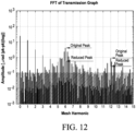
- the FFT of a single flank test of a measured real gear set in Figure 6 shows a different behavior than the analysis of the theoretical gearset in Figure 4 , especially in the higher mesh harmonic range.
- the graph shows the amplitude of the transmission error in ⁇ rad for the 0 to the 15 th mesh harmonic. Occurring mesh harmonics and additional sidebands are visible. The amplitude of the 6 th mesh harmonic is pronounced, which is not obvious in the analysis of the designed motion-error. In this case, the amplitude of the sixth mesh harmonic is at 9.4prad. It is assumed that additional surface structure effects (e.g.
- waviness which is the surface form (sine wave for example) of a plurality of flats or facets) on the standard ground flank lead to the effects of a higher 6 th mesh harmonic.
- they are replicated via a simulation with a purposely introduced surface structure ( Figure 7 ).
- Figure 7 a simulation with a purposely introduced surface structure
- six grooves are introduced per motion error parabola. This is done to replicate in the simulation the effects of the high sixth mesh harmonic that can be seen in Figure 5 .
- the amplitude of the grooves is chosen to deliver results that correlate to the real measurements shown in Figure 5 .
- the simulated transmission error does not only consist of the designed motion error, but also of a surface structure with a pattern of six grooves per motion error parabola.
- FIG. 8 shows the result of a FFT of a simulated single flank test of a gear set including an additional surface structure (e.g. waviness) and due to that, an additional excitation of the sixth mesh harmonic, correlating to the measurement of the real gear set.
- the graph shows the amplitude of the transmission error in ⁇ rad for the 0 to the 15 th mesh harmonic.
- An increased 6 th and 12 th mesh harmonic due to the introduction of the surface waviness is visible.
- the hatched area represents the results that are usually visually suppressed on a testing machine due to the low amplitudes.
- the simulation including the surface structure represents a simple model leading to the wanted replication of the effects of a higher 6 th mesh harmonic measured during a single flank test of the real gear set.
- Excitation problems can occur on both members of the gearset. If one member is already ground in a certain quantity, then counter actions can only be applied to the other member.
- a purposely introduced waviness to offset for the problems of the opposite member (e.g. US 2014/0256223 ) in spur or helical gears seems impractical in bevel gear grinding in particular if this requires dressing a waviness structure in the grinding wheel profile.
- the roll motion in generated pinions and gears and the plunging motion in non-generated gears will not allow transferring of certain grinding wheel profile waves to the flank surfaces.
- the process-affected relative sliding between grinding wheel profile and flank surfaces would wipe out sinusoidal or similar wave forms with maxima, minima and inflection points. Therefore, the inventive process does not use modifications to the grinding wheel profile, but uses process parameters (roll-positions) with or without additional machine motions to introduce and alter surface structures and is therefore limited to the generated member.
- a primary object of the invention is to change and improve the excitation behavior by changing the position of the surface structure (e.g. waviness) on each flank (structure shift), which is fundamentally different from the ideas of unequal tooth spacing that are mentioned in the state of the art.
- a change of the tooth spacing in a defined or random way will lower the gear quality according to the internationally defined standards. Tooth spacing variations may also cause negative side effects such as low frequency rumbling, which is not the case in the inventive process.
- the shift of the pattern from flank to flank is calculated via the following procedure:
- the amount of roll angle per line (RAPL) of the original axis-position table is calculated:
- RAPL Toe ⁇ roll ⁇ position ⁇ Heel ⁇ roll ⁇ position Number of lines in axis ⁇ position ⁇ table
- a single sine-wave is preferably utilized.
- FIG. 9 shows the results of the calculation of change in roll-position (start and end) that change the position of the introduced pattern on every flank in a predetermined way.
- the graph shows the sinusoidal arrangement of the shift for every flank. In this case the shift is given for a pinion with 7 teeth.
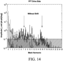
- FIG. 14 shows the measured FFT of real SFT ground at a roll-rate of 20°/second without any roll-position-shift. Every flank is ground the same way, leading to the same surface structure pattern on every flank.
- Significant peaks of the mesh harmonics are visible in the area of the 6 th to 8 th and 14 th to 16 th mesh harmonics.
- peaks can be seen at the 10 th and 11 th mesh harmonics.
- the hatched area represents the results that are usually visually suppressed on a testing machine due to the low amplitudes.
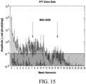
- Figure 15 shows the measured FFT of real SFT ground at a roll-rate of 20°/second with roll-position shift. The pattern is shifted from flank to flank. The lowering of peak harmonics in the area of the 7 th to 8 th mesh harmonic as well as in the area of the 14 th to 16 th mesh harmonics are visible. In addition sidebands are introduced.
Landscapes
- Engineering & Computer Science (AREA)
- Mechanical Engineering (AREA)
- Finish Polishing, Edge Sharpening, And Grinding By Specific Grinding Devices (AREA)
- Gear Processing (AREA)
- Gears, Cams (AREA)
- Grinding And Polishing Of Tertiary Curved Surfaces And Surfaces With Complex Shapes (AREA)
- Gear Transmission (AREA)
Claims (12)
- Procédé d'usinage par outil rotatif d'une roue conique comportant une pluralité de dents, ledit procédé comprenant un procédé de génération et :l'usinage d'une surface de flanc de dent concernant une première dent pour produire un motif de méplats spécifiques à l'usinage sur ladite surface de flanc de dent,l'usinage d'une surface de flanc de dent concernant une dent suivante pour produire un motif de méplats spécifiques à l'usinage sur ladite surface de flanc de dent, dans lequel, sous l'effet d'une modification d'usinage, le motif de méplats spécifiques à l'usinage réalisé sur la surface de flanc de dent concernant ladite dent suivante diffère du motif de méplats spécifiques à l'usinage réalisé sur la surface de flanc de dent concernant ladite première dent ;caractérisé en ce que ladite modification d'usinage comprend un décalage des positions de roulement de manière que tous les méplats ne soient pas positionnés de la même manière sur chaque flanc de dent et/ou une modification des distances des incréments d'angle de roulement concernant un roulement générateur dans lequel l'outil et la roue conique roulent l'un sur l'autre.
- Procédé selon la revendication 1, comprenant en outre l'usinage d'une surface de flanc de dent sur chacune des dents restantes de ladite pluralité de dents de ladite roue conique pour produire un motif de méplats spécifiques à l'usinage sur la surface de flanc de dent de chacune desdites dents restantes, ledit motif de méplats spécifiques à l'usinage réalisé sur la surface de flanc de dent de chacune desdites dents restantes comprenant un motif de méplats spécifiques à l'usinage différent du motif de méplats spécifiques à l'usinage réalisé sur une surface de flanc de dent usinée immédiatement précédente parmi lesdites dents restantes.
- Procédé selon la revendication 2, dans lequel ledit usinage d'une surface de flanc de dent comprend la mise en contact dudit outil rotatif et de ladite roue conique et le déplacement conjoint dudit outil et de ladite roue conique dans un roulement générateur qui commence en une certaine position de roulement et s'étend sur un certain angle de roulement,dans lequel la position de roulement relative à chaque surface de flanc de dent de ladite pluralité de dents est modifiée par rapport à la position de roulement d'une surface de flanc de dent usinée immédiatement précédente,moyennant quoi la position des méplats spécifiques à l'usinage réalisés sur une surface de flanc de dent est décalée par rapport à la position des méplats spécifiques à l'usinage réalisés sur une surface de flanc de dent usinée immédiatement précédente.
- Procédé selon la revendication 2, dans lequel ledit usinage d'une surface de flanc de dent comprend la mise en contact dudit outil rotatif et de ladite roue conique et le déplacement conjoint dudit outil et de ladite roue conique dans un roulement générateur qui commence en une certaine position de roulement et s'étend sur un certain angle de roulement,dans lequel l'angle de roulement relatif à chaque surface de flanc de dent de ladite pluralité de dents comprend une pluralité d'incréments d'angle de roulement, la grandeur de chaque incrément d'angle de roulement étant indicative de la largeur d'un méplat spécifique à l'usinage respectif, etdans lequel les incréments d'angle de roulement varient en grandeur le long de chaque surface de flanc de dent, produisant une variation correspondante de la largeur de chaque méplat spécifique à l'usinage le long de la surface de flanc de dent respective,moyennant quoi les largeurs variables des méplats spécifiques à l'usinage le long d'une surface de flanc de dent définissent un motif, ledit motif de largeurs variables des méplats spécifiques à l'usinage d'une surface de flanc de dent différant du motif de largeurs variables des méplats spécifiques à l'usinage d'une surface de flanc de dent usinée immédiatement précédente.
- Procédé selon la revendication 1, comprenant en outre la formation d'une structure de surface diffuse sur les surfaces de flanc de dent de ladite pluralité de dents de ladite roue conique.
- Procédé selon la revendication 1, dans lequel ledit usinage comprend un meulage.
- Procédé selon la revendication 1, dans lequel ledit usinage comprend un taillage.
- Procédé selon la revendication 7, dans lequel ledit taillage comprend le skiving.
- Procédé selon la revendication 3, dans lequel le décalage de la position des méplats spécifiques à l'usinage d'une surface de flanc de dent à l'autre suit une fonction prédéterminée.
- Procédé selon la revendication 9, dans lequel ladite fonction prédéterminée comprend une fonction linéaire, une fonction sinusoïdale ou une fonction d'ordre supérieur.
- Procédé selon la revendication 4, dans lequel le motif de largeurs variables des méplats spécifiques à l'usinage d'une surface de flanc de dent à l'autre suit une fonction prédéterminée.
- Procédé selon la revendication 11, dans lequel ladite fonction prédéterminée comprend une fonction linéaire, une fonction sinusoïdale ou une fonction d'ordre supérieur.
Applications Claiming Priority (2)
| Application Number | Priority Date | Filing Date | Title |
|---|---|---|---|
| US201562167459P | 2015-05-28 | 2015-05-28 | |
| PCT/US2016/034205 WO2016191509A1 (fr) | 2015-05-28 | 2016-05-26 | Décalage de structure de surface de flanc d'engrenage conique |
Publications (2)
| Publication Number | Publication Date |
|---|---|
| EP3302862A1 EP3302862A1 (fr) | 2018-04-11 |
| EP3302862B1 true EP3302862B1 (fr) | 2024-07-03 |
Family
ID=56113091
Family Applications (1)
| Application Number | Title | Priority Date | Filing Date |
|---|---|---|---|
| EP16727921.5A Active EP3302862B1 (fr) | 2015-05-28 | 2016-05-26 | Décalage de structure de surface de flanc d'engrenage conique |
Country Status (5)
| Country | Link |
|---|---|
| US (1) | US10702935B2 (fr) |
| EP (1) | EP3302862B1 (fr) |
| JP (1) | JP6910307B2 (fr) |
| CN (1) | CN107666980B (fr) |
| WO (1) | WO2016191509A1 (fr) |
Families Citing this family (8)
| Publication number | Priority date | Publication date | Assignee | Title |
|---|---|---|---|---|
| JP7316792B2 (ja) * | 2016-05-19 | 2023-07-28 | ザ グリーソン ワークス | ギアのトップランド面取り |
| DE102017000260A1 (de) * | 2017-01-12 | 2018-07-12 | Gleason-Pfauter Maschinenfabrik Gmbh | Verfahren zur hartfeinbearbeitung von verzahnungen, insbesondere innenverzahnungen und dazu geeignete werkzeugmaschine |
| EP3600744A1 (fr) * | 2017-03-28 | 2020-02-05 | Klingelnberg AG | Procédé pour l'usinage d'une piece de roue dentée et paire de roues dentées correspondante |
| DE102019004687A1 (de) * | 2019-07-02 | 2021-01-07 | Rheinisch-Westfälische Technische Hochschule (Rwth) Aachen | Verfahren zur Herstellung von Zahnflankenmodifikationen an Verzahnungen von Werkstücken sowie Werkzeuge zur Durchführung des Verfahrens |
| DE102019216345B4 (de) * | 2019-10-23 | 2022-08-25 | Robert Bosch Gmbh | Schnecke für ein Schneckengetriebe und Verfahren zum Herstellen solcher Schnecken |
| JP7753346B2 (ja) * | 2020-09-02 | 2025-10-14 | ザ グリーソン ワークス | 音響心理学的な歯フランク形状の修正 |
| CN115031678B (zh) * | 2022-06-13 | 2023-04-28 | 北京工业大学 | 一种基于齿廓波纹度信息和齿轮传动误差信息的噪声齿轮筛选方法 |
| ES3034935T3 (en) * | 2023-04-11 | 2025-08-26 | Reishauer Ag | Skiving tool and method for machining tooth flanks of a toothing by skiving |
Citations (1)
| Publication number | Priority date | Publication date | Assignee | Title |
|---|---|---|---|---|
| US3653290A (en) * | 1970-06-29 | 1972-04-04 | Gleason Works | Gear generating method and apparatus |
Family Cites Families (17)
| Publication number | Priority date | Publication date | Assignee | Title |
|---|---|---|---|---|
| US1502903A (en) | 1923-02-27 | 1924-07-29 | Gen Electric | Steam-turbine rotor and method of avoiding wave phenomena therein |
| US2207438A (en) * | 1932-01-26 | 1940-07-09 | Fellows Gear Shaper Co | Gear finishing apparatus |
| US3006604A (en) | 1958-12-02 | 1961-10-31 | Miller Charles La Forest | Self-reversing exducer for gas turbines |
| US3127709A (en) | 1962-07-09 | 1964-04-07 | Waguri Akira | Grinding method and grinding head for grinding tooth surfaces of gears with circular tooth trace |
| JPS5522206B2 (fr) * | 1972-02-23 | 1980-06-16 | ||
| US5140781A (en) * | 1992-01-13 | 1992-08-25 | Westinghouse Electric Corp. | Gear finishing process |
| DE19517359C1 (de) * | 1995-05-11 | 1996-07-04 | Klingelnberg Soehne | Kegelradpaar |
| JP2000039055A (ja) * | 1998-07-23 | 2000-02-08 | Mazda Motor Corp | 歯車部材及びその作成方法 |
| US6669415B2 (en) | 2001-02-16 | 2003-12-30 | The Gleason Works | Machine for producing bevel gears |
| DE10334493B4 (de) | 2003-07-29 | 2006-01-05 | Klingelnberg Gmbh | Verfahren zum Fräsen von Spiralkegelrädern |
| US7682222B2 (en) * | 2004-05-26 | 2010-03-23 | The Gleason Works | Variable rate method of machining gears |
| NL1029531C2 (nl) * | 2005-07-15 | 2007-01-16 | Hpg Nederland Bv | Tandwiel en tandwieloverbrenging. |
| US7462092B2 (en) | 2006-09-19 | 2008-12-09 | The Gleason Works | Method of finishing bevel gears to produce a diffuse surface structure |
| EP2314404B1 (fr) * | 2009-10-22 | 2012-06-20 | Klingelnberg AG | Procédé de traitement précis et dur des flancs de dents d'une roue dentée |
| JP5551950B2 (ja) * | 2010-03-19 | 2014-07-16 | 本田技研工業株式会社 | ヘリカル歯車の加工方法 |
| DE102011100699A1 (de) | 2010-06-01 | 2011-12-01 | Schaeffler Technologies Gmbh & Co. Kg | Drehmomentwandler mit asymmetrisch verteilt angeordneten Schaufeln |
| DE102013003795A1 (de) | 2013-03-05 | 2014-09-11 | Liebherr-Verzahntechnik Gmbh | Bearbeitungsverfahren zum Hartfeinbearbeiten von geräuschoptimierten Verzahnungen auf einer Verzahnmaschine |
-
2016
- 2016-05-26 EP EP16727921.5A patent/EP3302862B1/fr active Active
- 2016-05-26 US US15/572,520 patent/US10702935B2/en active Active
- 2016-05-26 JP JP2017561900A patent/JP6910307B2/ja active Active
- 2016-05-26 CN CN201680031156.3A patent/CN107666980B/zh active Active
- 2016-05-26 WO PCT/US2016/034205 patent/WO2016191509A1/fr not_active Ceased
Patent Citations (1)
| Publication number | Priority date | Publication date | Assignee | Title |
|---|---|---|---|---|
| US3653290A (en) * | 1970-06-29 | 1972-04-04 | Gleason Works | Gear generating method and apparatus |
Non-Patent Citations (1)
| Title |
|---|
| ANONYMOUS: "Wälzschleifen von Kegelrädern mit synchronisierter Exzenterbewegung", RESEARCH DISCLOSURE, vol. 577, no. 20, 10 April 2012 (2012-04-10), XP055627203 * |
Also Published As
| Publication number | Publication date |
|---|---|
| WO2016191509A1 (fr) | 2016-12-01 |
| CN107666980B (zh) | 2019-12-03 |
| CN107666980A (zh) | 2018-02-06 |
| EP3302862A1 (fr) | 2018-04-11 |
| US20180126471A1 (en) | 2018-05-10 |
| JP2018516180A (ja) | 2018-06-21 |
| JP6910307B2 (ja) | 2021-07-28 |
| US10702935B2 (en) | 2020-07-07 |
Similar Documents
| Publication | Publication Date | Title |
|---|---|---|
| EP3302862B1 (fr) | Décalage de structure de surface de flanc d'engrenage conique | |
| JP6466523B2 (ja) | ワークの製造方法、並びに、該製造方法を実行するための工具、歯切装置及びコンピュータプログラム | |
| Ren et al. | Influence of tool eccentricity on surface roughness in gear skiving | |
| EP2079556B1 (fr) | Procede de rodage d'engrenages | |
| EP2081720B1 (fr) | Procédé de finition d'engrenages coniques pour l'obtention d'une structure superficielle diffuse | |
| US12097566B2 (en) | Method of manufacturing a toothed bevel honing tool for honing a toothed bevel workpiece, a toothed bevel honing tool and method of honing bevel gears | |
| CN116018228B (zh) | 心理声学齿轮齿面形状修正 | |
| US9782848B2 (en) | Swing motion for manufacturing non-generated bevel gears with end relief | |
| JP6297074B2 (ja) | 斜め創成法による、ワークピースのギヤの機械加工方法、工具及びギヤ製造機 | |
| Shih et al. | Manufacture of face-hobbed straight bevel gears using a six-axis CNC bevel gear cutting machine | |
| JP2016135537A (ja) | 斜め創成法による、ワークピースのギヤの機械加工方法、その方法を実行するための工具、その工具のドレッシング方法、及びそれらの方法を実行するためのギヤ製造機 | |
| Chen et al. | A generic and theoretical approach to programming and post-processing for hypoid gear machining on multi-axis CNC face-milling machines | |
| US5716174A (en) | Tool feeding method | |
| EP1325792B1 (fr) | Outil et procédé de meulage de précision d'un engrenage conique plat qui engrene avec un pignon conique à developpante | |
| Strunk | Surface structure shift for ground bevel gears | |
| Olivoni | New developments and applications based on a numerical model for the optimisation of the centred gear skiving process | |
| Alexopoulos et al. | Investigation of the manufacturability of topological tooth flank modifications using adapted process kinematics for gear finish hobbing | |
| EP0850120A1 (fr) | Procede d'avance pour outil | |
| Stadtfeld | MicroPulse and MicroShift for ground bevel gearsets | |
| Stadtfeld | Gear Mathematics for Bevel and Hypoid Gears | |
| WO2025042667A1 (fr) | Génération de ligne de référence d'engrenages coniques droits | |
| JP2023055021A (ja) | 歯車加工方法 | |
| Stadtfeld | Prototyping on Bevel Gear Cutting and Grinding Machines |
Legal Events
| Date | Code | Title | Description |
|---|---|---|---|
| STAA | Information on the status of an ep patent application or granted ep patent |
Free format text: STATUS: THE INTERNATIONAL PUBLICATION HAS BEEN MADE |
|
| PUAI | Public reference made under article 153(3) epc to a published international application that has entered the european phase |
Free format text: ORIGINAL CODE: 0009012 |
|
| STAA | Information on the status of an ep patent application or granted ep patent |
Free format text: STATUS: REQUEST FOR EXAMINATION WAS MADE |
|
| 17P | Request for examination filed |
Effective date: 20171106 |
|
| AK | Designated contracting states |
Kind code of ref document: A1 Designated state(s): AL AT BE BG CH CY CZ DE DK EE ES FI FR GB GR HR HU IE IS IT LI LT LU LV MC MK MT NL NO PL PT RO RS SE SI SK SM TR |
|
| AX | Request for extension of the european patent |
Extension state: BA ME |
|
| STAA | Information on the status of an ep patent application or granted ep patent |
Free format text: STATUS: EXAMINATION IS IN PROGRESS |
|
| DAV | Request for validation of the european patent (deleted) | ||
| DAX | Request for extension of the european patent (deleted) | ||
| 17Q | First examination report despatched |
Effective date: 20180903 |
|
| TPAC | Observations filed by third parties |
Free format text: ORIGINAL CODE: EPIDOSNTIPA |
|
| GRAP | Despatch of communication of intention to grant a patent |
Free format text: ORIGINAL CODE: EPIDOSNIGR1 |
|
| STAA | Information on the status of an ep patent application or granted ep patent |
Free format text: STATUS: GRANT OF PATENT IS INTENDED |
|
| GRAS | Grant fee paid |
Free format text: ORIGINAL CODE: EPIDOSNIGR3 |
|
| INTG | Intention to grant announced |
Effective date: 20240424 |
|
| GRAA | (expected) grant |
Free format text: ORIGINAL CODE: 0009210 |
|
| STAA | Information on the status of an ep patent application or granted ep patent |
Free format text: STATUS: THE PATENT HAS BEEN GRANTED |
|
| P01 | Opt-out of the competence of the unified patent court (upc) registered |
Effective date: 20240522 |
|
| AK | Designated contracting states |
Kind code of ref document: B1 Designated state(s): AL AT BE BG CH CY CZ DE DK EE ES FI FR GB GR HR HU IE IS IT LI LT LU LV MC MK MT NL NO PL PT RO RS SE SI SK SM TR |
|
| REG | Reference to a national code |
Ref country code: CH Ref legal event code: EP |
|
| REG | Reference to a national code |
Ref country code: DE Ref legal event code: R096 Ref document number: 602016088213 Country of ref document: DE |
|
| REG | Reference to a national code |
Ref country code: LT Ref legal event code: MG9D |
|
| REG | Reference to a national code |
Ref country code: NL Ref legal event code: MP Effective date: 20240703 |
|
| PG25 | Lapsed in a contracting state [announced via postgrant information from national office to epo] |
Ref country code: PT Free format text: LAPSE BECAUSE OF FAILURE TO SUBMIT A TRANSLATION OF THE DESCRIPTION OR TO PAY THE FEE WITHIN THE PRESCRIBED TIME-LIMIT Effective date: 20241104 |
|
| REG | Reference to a national code |
Ref country code: AT Ref legal event code: MK05 Ref document number: 1699326 Country of ref document: AT Kind code of ref document: T Effective date: 20240703 |
|
| PG25 | Lapsed in a contracting state [announced via postgrant information from national office to epo] |
Ref country code: NL Free format text: LAPSE BECAUSE OF FAILURE TO SUBMIT A TRANSLATION OF THE DESCRIPTION OR TO PAY THE FEE WITHIN THE PRESCRIBED TIME-LIMIT Effective date: 20240703 |
|
| PG25 | Lapsed in a contracting state [announced via postgrant information from national office to epo] |
Ref country code: PT Free format text: LAPSE BECAUSE OF FAILURE TO SUBMIT A TRANSLATION OF THE DESCRIPTION OR TO PAY THE FEE WITHIN THE PRESCRIBED TIME-LIMIT Effective date: 20241104 Ref country code: NL Free format text: LAPSE BECAUSE OF FAILURE TO SUBMIT A TRANSLATION OF THE DESCRIPTION OR TO PAY THE FEE WITHIN THE PRESCRIBED TIME-LIMIT Effective date: 20240703 |
|
| PG25 | Lapsed in a contracting state [announced via postgrant information from national office to epo] |
Ref country code: NO Free format text: LAPSE BECAUSE OF FAILURE TO SUBMIT A TRANSLATION OF THE DESCRIPTION OR TO PAY THE FEE WITHIN THE PRESCRIBED TIME-LIMIT Effective date: 20241003 |
|
| PG25 | Lapsed in a contracting state [announced via postgrant information from national office to epo] |
Ref country code: PL Free format text: LAPSE BECAUSE OF FAILURE TO SUBMIT A TRANSLATION OF THE DESCRIPTION OR TO PAY THE FEE WITHIN THE PRESCRIBED TIME-LIMIT Effective date: 20240703 Ref country code: FI Free format text: LAPSE BECAUSE OF FAILURE TO SUBMIT A TRANSLATION OF THE DESCRIPTION OR TO PAY THE FEE WITHIN THE PRESCRIBED TIME-LIMIT Effective date: 20240703 Ref country code: GR Free format text: LAPSE BECAUSE OF FAILURE TO SUBMIT A TRANSLATION OF THE DESCRIPTION OR TO PAY THE FEE WITHIN THE PRESCRIBED TIME-LIMIT Effective date: 20241004 |
|
| PG25 | Lapsed in a contracting state [announced via postgrant information from national office to epo] |
Ref country code: BG Free format text: LAPSE BECAUSE OF FAILURE TO SUBMIT A TRANSLATION OF THE DESCRIPTION OR TO PAY THE FEE WITHIN THE PRESCRIBED TIME-LIMIT Effective date: 20240703 |
|
| PG25 | Lapsed in a contracting state [announced via postgrant information from national office to epo] |
Ref country code: LV Free format text: LAPSE BECAUSE OF FAILURE TO SUBMIT A TRANSLATION OF THE DESCRIPTION OR TO PAY THE FEE WITHIN THE PRESCRIBED TIME-LIMIT Effective date: 20240703 |
|
| PG25 | Lapsed in a contracting state [announced via postgrant information from national office to epo] |
Ref country code: IS Free format text: LAPSE BECAUSE OF FAILURE TO SUBMIT A TRANSLATION OF THE DESCRIPTION OR TO PAY THE FEE WITHIN THE PRESCRIBED TIME-LIMIT Effective date: 20241103 Ref country code: AT Free format text: LAPSE BECAUSE OF FAILURE TO SUBMIT A TRANSLATION OF THE DESCRIPTION OR TO PAY THE FEE WITHIN THE PRESCRIBED TIME-LIMIT Effective date: 20240703 |
|
| PG25 | Lapsed in a contracting state [announced via postgrant information from national office to epo] |
Ref country code: CZ Free format text: LAPSE BECAUSE OF FAILURE TO SUBMIT A TRANSLATION OF THE DESCRIPTION OR TO PAY THE FEE WITHIN THE PRESCRIBED TIME-LIMIT Effective date: 20240703 Ref country code: HR Free format text: LAPSE BECAUSE OF FAILURE TO SUBMIT A TRANSLATION OF THE DESCRIPTION OR TO PAY THE FEE WITHIN THE PRESCRIBED TIME-LIMIT Effective date: 20240703 |
|
| PG25 | Lapsed in a contracting state [announced via postgrant information from national office to epo] |
Ref country code: ES Free format text: LAPSE BECAUSE OF FAILURE TO SUBMIT A TRANSLATION OF THE DESCRIPTION OR TO PAY THE FEE WITHIN THE PRESCRIBED TIME-LIMIT Effective date: 20240703 Ref country code: RS Free format text: LAPSE BECAUSE OF FAILURE TO SUBMIT A TRANSLATION OF THE DESCRIPTION OR TO PAY THE FEE WITHIN THE PRESCRIBED TIME-LIMIT Effective date: 20241003 |
|
| PG25 | Lapsed in a contracting state [announced via postgrant information from national office to epo] |
Ref country code: RS Free format text: LAPSE BECAUSE OF FAILURE TO SUBMIT A TRANSLATION OF THE DESCRIPTION OR TO PAY THE FEE WITHIN THE PRESCRIBED TIME-LIMIT Effective date: 20241003 Ref country code: PL Free format text: LAPSE BECAUSE OF FAILURE TO SUBMIT A TRANSLATION OF THE DESCRIPTION OR TO PAY THE FEE WITHIN THE PRESCRIBED TIME-LIMIT Effective date: 20240703 Ref country code: NO Free format text: LAPSE BECAUSE OF FAILURE TO SUBMIT A TRANSLATION OF THE DESCRIPTION OR TO PAY THE FEE WITHIN THE PRESCRIBED TIME-LIMIT Effective date: 20241003 Ref country code: LV Free format text: LAPSE BECAUSE OF FAILURE TO SUBMIT A TRANSLATION OF THE DESCRIPTION OR TO PAY THE FEE WITHIN THE PRESCRIBED TIME-LIMIT Effective date: 20240703 Ref country code: IS Free format text: LAPSE BECAUSE OF FAILURE TO SUBMIT A TRANSLATION OF THE DESCRIPTION OR TO PAY THE FEE WITHIN THE PRESCRIBED TIME-LIMIT Effective date: 20241103 Ref country code: HR Free format text: LAPSE BECAUSE OF FAILURE TO SUBMIT A TRANSLATION OF THE DESCRIPTION OR TO PAY THE FEE WITHIN THE PRESCRIBED TIME-LIMIT Effective date: 20240703 Ref country code: GR Free format text: LAPSE BECAUSE OF FAILURE TO SUBMIT A TRANSLATION OF THE DESCRIPTION OR TO PAY THE FEE WITHIN THE PRESCRIBED TIME-LIMIT Effective date: 20241004 Ref country code: FI Free format text: LAPSE BECAUSE OF FAILURE TO SUBMIT A TRANSLATION OF THE DESCRIPTION OR TO PAY THE FEE WITHIN THE PRESCRIBED TIME-LIMIT Effective date: 20240703 Ref country code: ES Free format text: LAPSE BECAUSE OF FAILURE TO SUBMIT A TRANSLATION OF THE DESCRIPTION OR TO PAY THE FEE WITHIN THE PRESCRIBED TIME-LIMIT Effective date: 20240703 Ref country code: CZ Free format text: LAPSE BECAUSE OF FAILURE TO SUBMIT A TRANSLATION OF THE DESCRIPTION OR TO PAY THE FEE WITHIN THE PRESCRIBED TIME-LIMIT Effective date: 20240703 Ref country code: BG Free format text: LAPSE BECAUSE OF FAILURE TO SUBMIT A TRANSLATION OF THE DESCRIPTION OR TO PAY THE FEE WITHIN THE PRESCRIBED TIME-LIMIT Effective date: 20240703 Ref country code: AT Free format text: LAPSE BECAUSE OF FAILURE TO SUBMIT A TRANSLATION OF THE DESCRIPTION OR TO PAY THE FEE WITHIN THE PRESCRIBED TIME-LIMIT Effective date: 20240703 |
|
| REG | Reference to a national code |
Ref country code: DE Ref legal event code: R097 Ref document number: 602016088213 Country of ref document: DE |
|
| PG25 | Lapsed in a contracting state [announced via postgrant information from national office to epo] |
Ref country code: DK Free format text: LAPSE BECAUSE OF FAILURE TO SUBMIT A TRANSLATION OF THE DESCRIPTION OR TO PAY THE FEE WITHIN THE PRESCRIBED TIME-LIMIT Effective date: 20240703 Ref country code: RO Free format text: LAPSE BECAUSE OF FAILURE TO SUBMIT A TRANSLATION OF THE DESCRIPTION OR TO PAY THE FEE WITHIN THE PRESCRIBED TIME-LIMIT Effective date: 20240703 Ref country code: SM Free format text: LAPSE BECAUSE OF FAILURE TO SUBMIT A TRANSLATION OF THE DESCRIPTION OR TO PAY THE FEE WITHIN THE PRESCRIBED TIME-LIMIT Effective date: 20240703 |
|
| PG25 | Lapsed in a contracting state [announced via postgrant information from national office to epo] |
Ref country code: EE Free format text: LAPSE BECAUSE OF FAILURE TO SUBMIT A TRANSLATION OF THE DESCRIPTION OR TO PAY THE FEE WITHIN THE PRESCRIBED TIME-LIMIT Effective date: 20240703 |
|
| PG25 | Lapsed in a contracting state [announced via postgrant information from national office to epo] |
Ref country code: SK Free format text: LAPSE BECAUSE OF FAILURE TO SUBMIT A TRANSLATION OF THE DESCRIPTION OR TO PAY THE FEE WITHIN THE PRESCRIBED TIME-LIMIT Effective date: 20240703 |
|
| PLBE | No opposition filed within time limit |
Free format text: ORIGINAL CODE: 0009261 |
|
| STAA | Information on the status of an ep patent application or granted ep patent |
Free format text: STATUS: NO OPPOSITION FILED WITHIN TIME LIMIT |
|
| 26N | No opposition filed |
Effective date: 20250404 |
|
| PGFP | Annual fee paid to national office [announced via postgrant information from national office to epo] |
Ref country code: DE Payment date: 20250529 Year of fee payment: 10 |
|
| PGFP | Annual fee paid to national office [announced via postgrant information from national office to epo] |
Ref country code: IT Payment date: 20250521 Year of fee payment: 10 |
|
| PGFP | Annual fee paid to national office [announced via postgrant information from national office to epo] |
Ref country code: CH Payment date: 20250601 Year of fee payment: 10 |
|
| PG25 | Lapsed in a contracting state [announced via postgrant information from national office to epo] |
Ref country code: SE Free format text: LAPSE BECAUSE OF FAILURE TO SUBMIT A TRANSLATION OF THE DESCRIPTION OR TO PAY THE FEE WITHIN THE PRESCRIBED TIME-LIMIT Effective date: 20240703 |
|
| PG25 | Lapsed in a contracting state [announced via postgrant information from national office to epo] |
Ref country code: LU Free format text: LAPSE BECAUSE OF NON-PAYMENT OF DUE FEES Effective date: 20250526 |
|
| GBPC | Gb: european patent ceased through non-payment of renewal fee |
Effective date: 20250526 |
|
| REG | Reference to a national code |
Ref country code: BE Ref legal event code: MM Effective date: 20250531 |
|
| PG25 | Lapsed in a contracting state [announced via postgrant information from national office to epo] |
Ref country code: MC Free format text: LAPSE BECAUSE OF FAILURE TO SUBMIT A TRANSLATION OF THE DESCRIPTION OR TO PAY THE FEE WITHIN THE PRESCRIBED TIME-LIMIT Effective date: 20240703 |
|
| PG25 | Lapsed in a contracting state [announced via postgrant information from national office to epo] |
Ref country code: GB Free format text: LAPSE BECAUSE OF NON-PAYMENT OF DUE FEES Effective date: 20250526 |
|
| PG25 | Lapsed in a contracting state [announced via postgrant information from national office to epo] |
Ref country code: IE Free format text: LAPSE BECAUSE OF NON-PAYMENT OF DUE FEES Effective date: 20250526 |
|
| PG25 | Lapsed in a contracting state [announced via postgrant information from national office to epo] |
Ref country code: BE Free format text: LAPSE BECAUSE OF NON-PAYMENT OF DUE FEES Effective date: 20250531 |
|
| PG25 | Lapsed in a contracting state [announced via postgrant information from national office to epo] |
Ref country code: FR Free format text: LAPSE BECAUSE OF NON-PAYMENT OF DUE FEES Effective date: 20250531 |