EP3302913B1 - Dispositif et procédé pour réaliser un moulage de caractéristiques de surface - Google Patents
Dispositif et procédé pour réaliser un moulage de caractéristiques de surface Download PDFInfo
- Publication number
- EP3302913B1 EP3302913B1 EP16729799.3A EP16729799A EP3302913B1 EP 3302913 B1 EP3302913 B1 EP 3302913B1 EP 16729799 A EP16729799 A EP 16729799A EP 3302913 B1 EP3302913 B1 EP 3302913B1
- Authority
- EP
- European Patent Office
- Prior art keywords
- impression
- blank
- layer
- punch
- carrier
- Prior art date
- Legal status (The legal status is an assumption and is not a legal conclusion. Google has not performed a legal analysis and makes no representation as to the accuracy of the status listed.)
- Active
Links
Images


Classifications
-
- B—PERFORMING OPERATIONS; TRANSPORTING
- B29—WORKING OF PLASTICS; WORKING OF SUBSTANCES IN A PLASTIC STATE IN GENERAL
- B29C—SHAPING OR JOINING OF PLASTICS; SHAPING OF MATERIAL IN A PLASTIC STATE, NOT OTHERWISE PROVIDED FOR; AFTER-TREATMENT OF THE SHAPED PRODUCTS, e.g. REPAIRING
- B29C43/00—Compression moulding, i.e. applying external pressure to flow the moulding material; Apparatus therefor
- B29C43/32—Component parts, details or accessories; Auxiliary operations
- B29C43/36—Moulds for making articles of definite length, i.e. discrete articles
- B29C43/361—Moulds for making articles of definite length, i.e. discrete articles with pressing members independently movable of the parts for opening or closing the mould, e.g. movable pistons
-
- B—PERFORMING OPERATIONS; TRANSPORTING
- B29—WORKING OF PLASTICS; WORKING OF SUBSTANCES IN A PLASTIC STATE IN GENERAL
- B29C—SHAPING OR JOINING OF PLASTICS; SHAPING OF MATERIAL IN A PLASTIC STATE, NOT OTHERWISE PROVIDED FOR; AFTER-TREATMENT OF THE SHAPED PRODUCTS, e.g. REPAIRING
- B29C43/00—Compression moulding, i.e. applying external pressure to flow the moulding material; Apparatus therefor
- B29C43/02—Compression moulding, i.e. applying external pressure to flow the moulding material; Apparatus therefor of articles of definite length, i.e. discrete articles
- B29C43/18—Compression moulding, i.e. applying external pressure to flow the moulding material; Apparatus therefor of articles of definite length, i.e. discrete articles incorporating preformed parts or layers, e.g. compression moulding around inserts or for coating articles
-
- B—PERFORMING OPERATIONS; TRANSPORTING
- B29—WORKING OF PLASTICS; WORKING OF SUBSTANCES IN A PLASTIC STATE IN GENERAL
- B29C—SHAPING OR JOINING OF PLASTICS; SHAPING OF MATERIAL IN A PLASTIC STATE, NOT OTHERWISE PROVIDED FOR; AFTER-TREATMENT OF THE SHAPED PRODUCTS, e.g. REPAIRING
- B29C43/00—Compression moulding, i.e. applying external pressure to flow the moulding material; Apparatus therefor
- B29C43/32—Component parts, details or accessories; Auxiliary operations
- B29C43/52—Heating or cooling
-
- B—PERFORMING OPERATIONS; TRANSPORTING
- B29—WORKING OF PLASTICS; WORKING OF SUBSTANCES IN A PLASTIC STATE IN GENERAL
- B29C—SHAPING OR JOINING OF PLASTICS; SHAPING OF MATERIAL IN A PLASTIC STATE, NOT OTHERWISE PROVIDED FOR; AFTER-TREATMENT OF THE SHAPED PRODUCTS, e.g. REPAIRING
- B29C43/00—Compression moulding, i.e. applying external pressure to flow the moulding material; Apparatus therefor
- B29C43/32—Component parts, details or accessories; Auxiliary operations
- B29C43/58—Measuring, controlling or regulating
-
- G—PHYSICS
- G01—MEASURING; TESTING
- G01Q—SCANNING-PROBE TECHNIQUES OR APPARATUS; APPLICATIONS OF SCANNING-PROBE TECHNIQUES, e.g. SCANNING PROBE MICROSCOPY [SPM]
- G01Q30/00—Auxiliary means serving to assist or improve the scanning probe techniques or apparatus, e.g. display or data processing devices
- G01Q30/20—Sample handling devices or methods
-
- B—PERFORMING OPERATIONS; TRANSPORTING
- B29—WORKING OF PLASTICS; WORKING OF SUBSTANCES IN A PLASTIC STATE IN GENERAL
- B29C—SHAPING OR JOINING OF PLASTICS; SHAPING OF MATERIAL IN A PLASTIC STATE, NOT OTHERWISE PROVIDED FOR; AFTER-TREATMENT OF THE SHAPED PRODUCTS, e.g. REPAIRING
- B29C35/00—Heating, cooling or curing, e.g. crosslinking or vulcanising; Apparatus therefor
- B29C35/02—Heating or curing, e.g. crosslinking or vulcanizing during moulding, e.g. in a mould
- B29C35/08—Heating or curing, e.g. crosslinking or vulcanizing during moulding, e.g. in a mould by wave energy or particle radiation
- B29C35/0805—Heating or curing, e.g. crosslinking or vulcanizing during moulding, e.g. in a mould by wave energy or particle radiation using electromagnetic radiation
- B29C2035/0827—Heating or curing, e.g. crosslinking or vulcanizing during moulding, e.g. in a mould by wave energy or particle radiation using electromagnetic radiation using UV radiation
-
- B—PERFORMING OPERATIONS; TRANSPORTING
- B29—WORKING OF PLASTICS; WORKING OF SUBSTANCES IN A PLASTIC STATE IN GENERAL
- B29C—SHAPING OR JOINING OF PLASTICS; SHAPING OF MATERIAL IN A PLASTIC STATE, NOT OTHERWISE PROVIDED FOR; AFTER-TREATMENT OF THE SHAPED PRODUCTS, e.g. REPAIRING
- B29C43/00—Compression moulding, i.e. applying external pressure to flow the moulding material; Apparatus therefor
- B29C43/32—Component parts, details or accessories; Auxiliary operations
- B29C43/36—Moulds for making articles of definite length, i.e. discrete articles
- B29C43/361—Moulds for making articles of definite length, i.e. discrete articles with pressing members independently movable of the parts for opening or closing the mould, e.g. movable pistons
- B29C2043/3615—Forming elements, e.g. mandrels or rams or stampers or pistons or plungers or punching devices
-
- B—PERFORMING OPERATIONS; TRANSPORTING
- B29—WORKING OF PLASTICS; WORKING OF SUBSTANCES IN A PLASTIC STATE IN GENERAL
- B29C—SHAPING OR JOINING OF PLASTICS; SHAPING OF MATERIAL IN A PLASTIC STATE, NOT OTHERWISE PROVIDED FOR; AFTER-TREATMENT OF THE SHAPED PRODUCTS, e.g. REPAIRING
- B29C43/00—Compression moulding, i.e. applying external pressure to flow the moulding material; Apparatus therefor
- B29C43/32—Component parts, details or accessories; Auxiliary operations
- B29C43/36—Moulds for making articles of definite length, i.e. discrete articles
- B29C43/361—Moulds for making articles of definite length, i.e. discrete articles with pressing members independently movable of the parts for opening or closing the mould, e.g. movable pistons
- B29C2043/3615—Forming elements, e.g. mandrels or rams or stampers or pistons or plungers or punching devices
- B29C2043/3626—Forming elements, e.g. mandrels or rams or stampers or pistons or plungers or punching devices multi-part rams, plungers or mandrels
-
- B—PERFORMING OPERATIONS; TRANSPORTING
- B29—WORKING OF PLASTICS; WORKING OF SUBSTANCES IN A PLASTIC STATE IN GENERAL
- B29C—SHAPING OR JOINING OF PLASTICS; SHAPING OF MATERIAL IN A PLASTIC STATE, NOT OTHERWISE PROVIDED FOR; AFTER-TREATMENT OF THE SHAPED PRODUCTS, e.g. REPAIRING
- B29C43/00—Compression moulding, i.e. applying external pressure to flow the moulding material; Apparatus therefor
- B29C43/32—Component parts, details or accessories; Auxiliary operations
- B29C43/58—Measuring, controlling or regulating
- B29C2043/5808—Measuring, controlling or regulating pressure or compressing force
-
- B—PERFORMING OPERATIONS; TRANSPORTING
- B29—WORKING OF PLASTICS; WORKING OF SUBSTANCES IN A PLASTIC STATE IN GENERAL
- B29C—SHAPING OR JOINING OF PLASTICS; SHAPING OF MATERIAL IN A PLASTIC STATE, NOT OTHERWISE PROVIDED FOR; AFTER-TREATMENT OF THE SHAPED PRODUCTS, e.g. REPAIRING
- B29C35/00—Heating, cooling or curing, e.g. crosslinking or vulcanising; Apparatus therefor
- B29C35/02—Heating or curing, e.g. crosslinking or vulcanizing during moulding, e.g. in a mould
- B29C35/08—Heating or curing, e.g. crosslinking or vulcanizing during moulding, e.g. in a mould by wave energy or particle radiation
- B29C35/0805—Heating or curing, e.g. crosslinking or vulcanizing during moulding, e.g. in a mould by wave energy or particle radiation using electromagnetic radiation
-
- B—PERFORMING OPERATIONS; TRANSPORTING
- B29—WORKING OF PLASTICS; WORKING OF SUBSTANCES IN A PLASTIC STATE IN GENERAL
- B29C—SHAPING OR JOINING OF PLASTICS; SHAPING OF MATERIAL IN A PLASTIC STATE, NOT OTHERWISE PROVIDED FOR; AFTER-TREATMENT OF THE SHAPED PRODUCTS, e.g. REPAIRING
- B29C43/00—Compression moulding, i.e. applying external pressure to flow the moulding material; Apparatus therefor
- B29C43/02—Compression moulding, i.e. applying external pressure to flow the moulding material; Apparatus therefor of articles of definite length, i.e. discrete articles
- B29C43/021—Compression moulding, i.e. applying external pressure to flow the moulding material; Apparatus therefor of articles of definite length, i.e. discrete articles characterised by the shape of the surface
Definitions
- the invention relates to a device according to claim 1 and a method according to claim 12.
- the invention relates to a device for producing an impression of surface properties with a housing, with a displaceable pressure stamp mounted on or in the housing and which can be pressed onto the surface, which has a blank carrier with a pressure surface which can be pressed onto the surface and on which an impression blank with an impression layer made of a hardenable material and can be releasably fixed, and with a hardening device which is arranged on or in the housing and with which the hardenable material of the impression blank can be hardened while it is being pressed onto the surface.
- Atomic force microscopy enables non-destructive and high-resolution imaging of a surface topography.
- the surface examined with the atomic force microscopy must be scanned with an elastically mounted measuring probe with high resolution, which requires a long measuring time of usually several minutes per image.
- the surface intended for the surface analysis must be brought within the detection range of the measuring probe. Comparable requirements and restrictions with regard to the surfaces that are suitable and sufficiently accessible for the analysis also apply to other optical or microscopic examination methods or to spectroscopic analyses.
- a soft metal foil can be pressed onto the surface to be examined in order to mold the surface topography.
- the molded soft metal foil can then be analyzed, for example using optical microscopes or using an atomic force microscope, in order to generate images of the surface topography of the surface to be analyzed.
- liquid polymer materials or polymer materials designed as a film or foil on the surface, which can be activated, for example, by heat or radiation and harden by crosslinking in order to mold the surface topography.
- curable polymer materials regularly only allow an impression of the surface topography, ie the three-dimensional structuring of the surface to be impressioned. It would be advantageous if, in addition to the surface topography, other surface properties were also included in an impression mapped and made available for subsequent measurements and analyses.
- the housing is adapted for manual use and handling and the device for producing an impression can be set up on a surface to be impressioned.
- a prefabricated impression blank can be pressed onto a surface in a simple and reproducible manner in order to carry out an impression of a surface with an impression layer made of a hardenable material.
- the impression blank is intended as a consumable material for a one-off impression of a surface, while the device according to the invention can be reused and used to produce a large number of impressions, each with new impression blanks.
- the separately produced impression blank is expediently fixed to the blank carrier before the start of the molding process, pressed against the surface with the blank carrier and, after the hardening, on the surface pressed hardening material of the impression blank released from the blank carrier again.
- the housing is adapted for manual use and handling.
- the housing can, for example, be configured approximately cylindrically and have a diameter of a few centimeters to about 10 or 15 centimeters that is easy to grasp or encompass with one hand.
- the housing can also have almost any other shape and can be designed, for example, in the shape of a hemisphere or cuboid.
- the plunger can be mounted on or in the housing such that it can be displaced linearly or pivoted about a pivot axis.
- the pressure plunger can be pressed against the surface both manually and with the aid of a spring force applied by a spring device or, for example, electrically with an actuator.
- Such a device can be used in various areas of application such as anilox roller inspection, quality assurance of production processes in the semiconductor industry, in-process inspections such as thermal spraying processes or in the context of research and development for prototypes and analyzes in order to reliably and precisely determine the mold the surface to be examined and be able to keep it ready for subsequent analysis procedures.
- the device should be shaped as ergonomically as possible and have a sufficiently robust mechanism to be able to carry out a large number of impressions with high precision and reproducibility over a long period of use.
- surfaces can be examined that cannot be analyzed in a standardized manner using conventional means and methods.
- Surfaces that are difficult to access such as the interior of a combustion engine or uneven surface contours, can be molded quickly and reliably.
- the surface to be examined does not have to be placed in a measuring device.
- the surface only has to be accessible for the duration of the molding process, so that a surface of a production machine is only needed for the molding for a short time and cost-intensive downtimes of the production machine can be minimized, since the time-consuming analysis of the surface can be carried out on the molding.
- Changes in a surface over time can also be analyzed by several successively generated impressions and the impressions can be archived for subsequent examinations.
- the pressure stamp By means of the pressure stamp, which can be displaced manually or with the help of a spring force of a spring device and pressed against the surface, a contact pressure that is sufficient for the impression and at the same time not excessively high can be generated and maintained uniformly for the duration of the curing of the curable material.
- Manual application or attachment of an impression layer made of a hardenable material is not required. This simplifies the production of an impression and makes it reproducible with a high level of accuracy, even for an inexperienced user.
- the contact pressure can for example depending on the curable material used, but also depending on the surface to be molded and in particular on its topography and wettability. In individual applications, the contact pressure can also be very low and possibly cause the impression blank to come into contact with the surface almost without pressure.
- the surface properties that are decisive for the subsequent measurement and evaluation are transferred to the impression layer and fixed by curing.
- the curing process of the curable material can expediently be activated, for example, by a suitable supply of energy, and can be carried out and completed quickly after activation.
- the impression layer expediently consists of a suitable cross-linking polymer material which takes on the properties relevant to the impression, such as topography or magnetization or hydrophobicity of the surface, while it is being pressed onto the surface to be impressioned and which it retains during curing.
- properties relevant to the impression such as topography or magnetization or hydrophobicity of the surface
- other surface properties such as the magnetization or hydrophobicity of the surface can also be shaped and preserved or made available for subsequent analyses.
- a suitable material or a suitable combination of materials for the molding layer By using a suitable material or a suitable combination of materials for the molding layer, another surface property or even several other surface properties can be molded in addition to the surface topography and made available for subsequent analyzes without spatial contact with the molded surface.
- electric, magnetic or electromagnetic fields prevailing in the area of the surface as well as temperature gradients or chemical properties are regarded as surface properties that can be molded with the impression.
- the blank carrier can consist of a dimensionally stable material or at least form a dimensionally stable pressure surface. It is also conceivable that the blank carrier has an elastic coating or an elastic pressure structure which forms the pressure surface in order, for example, to enable the impression blank to be pressed as evenly as possible on the surface to be molded.
- the blank carrier can also have an elastic or flexible membrane that can be hydraulically or pneumatically deflected in the direction of the surface to be molded and pressed against the surface to press the molding blank in order to press the molding blank arranged in between against the surface.
- the blank carrier is pivotably mounted. In this way it can be achieved that even with surfaces that are not completely flat, an approximately equally large contact pressure is exerted by the pivotably mounted blank carrier on the impression layer, which is pressed against the surface.
- the blank carrier can have at least two pressure segments which can be displaced relative to one another.
- Two pressure segments that can be displaced relative to one another can be implemented, for example, by a stationary pressure segment and a second, displaceably mounted pressure segment.
- the blank carrier can also consist of, for example, four or seven rectangular or honeycomb-shaped pressure segments that are arranged next to one another and form the pressure surface on which the impression blank can be fixed and pressed against the surface by moving the pressure plunger.
- the individual pressure segments can each be pivoted separately about a pivot axis or with a ball joint in all directions.
- the pressure surface formed by the several pressure segments can thus also be adapted to curved surfaces and, if necessary, compensate for unevenness in the surface to be molded.
- the impression blank is designed to be flexible or elastic before the impression layer made of the curable material hardens, a suitable configuration of a blank carrier divided into several pressure segments can enable individual adaptation of the impression blank to an uneven surface.
- the device has a positioning device for the movable pressure stamp having.
- the cylindrical or hemispherical housing can have an annular contact flange, which can be placed concentrically around the surface area to be shaped and fixed in this position, for example with adhesive.
- the course of the contact flange can deviate and be adapted to the relevant housing shape.
- the housing prefferably has a plurality of conically tapered formations along a housing edge surrounding the pressure surface of the blank carrier, each of which forms an approximately punctiform contact surface for the housing on the surface.
- the tips projecting towards the surface facilitate repeatable positioning and reliable fixation of the housing on the surface to be molded.
- the housing prefferably has one or more adhesive surfaces or suction devices or bores on the side next to the pressure surface of the blank carrier, in order to attach the housing to the surface to be molded by adhesion, suction with vacuum or with the aid of suitable fastening means such as screws or bolts.
- the device has a force measuring device, with which a tensile force or compressive force exerted on the plunger can be detected.
- the force-measuring device can be, for example, a piezo sensor that detects a forced deformation. It is also possible for the force-measuring device to have a deformation element whose deformation caused by the action of the force can be detected, for example, with strain gauges and converted into an electrical measurement signal.
- the force-measuring device can be designed in such a way that the force-measuring device can be used to detect a compressive force, a tensile force or both compressive forces and tensile forces that are applied when the impression blank is pressed on or when the hardened impression is detached.
- the force-measuring device is arranged on a guide rod of the pressure stamp.
- the force-measuring device can be arranged directly adjacent to or in a transition area to the blank carrier to the during the pressing of the plunger on the surface To be able to detect the blank carrier and the pressure forces exerted on the impression layer as accurately as possible.
- the device has a deformation body mounted with a displacement device, which can be pressed against the surface by an actuating device in order to bring about a deformation of the surface.
- the deformation body can be, for example, a pin, a cone or a tip, which dips into the surface with a sufficiently high contact pressure and causes a deformation of the topography of the surface.
- the displacement device for displacing the deformable body can, for example, have a spring force device that can be actuated manually or automatically and presses the deformable body against the surface with a definable and optionally adjustable spring force.
- the displacement device can also have an electromotive, magnetic or hydraulic drive device, for example, with which the deformation body is displaced and, in conjunction with a suitably designed force measuring device, a controllable or adjustable contact pressure of the deformation body on the surface is generated.
- an electromotive, magnetic or hydraulic drive device for example, with which the deformation body is displaced and, in conjunction with a suitably designed force measuring device, a controllable or adjustable contact pressure of the deformation body on the surface is generated.
- the invention provides that the deformation body is mounted displaceably in the blank carrier between a pressing position protruding from the blank carrier beyond the pressure surface and a rest position retracted into the blank carrier and not protruding over the pressure surface is.
- the deformation body can be stored within the blank carrier or above the blank carrier at a distance from the surface in the rest position, without requiring any additional space worth mentioning.
- the deformation body can be shifted out of the blank carrier and pressed into the surface via the pressure stamp.
- the impression blank must either only be fixed to the blank carrier and pressed against the deformed surface after the surface has been deformed and the deformation body has then been moved back into its rest position, or it must be ring-shaped, for example, and surround the deformation body protruding from the blank carrier, which then also during hardening of the impression layer is pressed into the surface and causes the deformation of the surface.
- the forced deformation of an elastic body can also be detected with the impression, which would reform again or change again after removal of the deformation body.
- the hardenable material of the impression layer is expediently selected and specified in such a way that the hardening process of the hardenable material can be activated or started in a suitable manner and carried out or completed quickly.
- the curing device can generate suitable activation energy or curing energy that supports the curing process.
- the curing device can, for example, generate heat or cold or generate a magnetic or electric field or generate electromagnetic radiation with which the curing process can be activated or supported.
- the curable material preferably has a low viscosity and surface energy in order to allow the surface to be molded as accurately as possible.
- the cured material should have low adhesion and sufficient elasticity to be able to be detached easily and non-destructively from the surface after the curing process.
- the hardened material can also be hardened stiff and rigid or high-strength.
- the curing device has an illumination device with which electromagnetic radiation can be emitted.
- the lighting device emits UV radiation.
- Suitable light-emitting diodes that can emit high-energy UV radiation are inexpensive and available with high luminosity.
- the use of UV radiation to activate and carry out the curing process can reduce and possibly even largely rule out any heating of the surface that is undesirable and disadvantageous for the surface to be molded.
- the curing device can advantageously be integrated into the blank carrier, particularly when it is an illumination device.
- the blank carrier can have a cavity in which the lighting device is arranged and which has a cover that is permeable to thermal radiation or UV light and on which the molding blank can be arranged and fixed.
- the cover can be, for example, a transparent rigid plastic material or a flexible foil.
- the pressure surface of the blank carrier has an adhesive layer for the detachable fixing of the impression blank.
- the adhesive layer can, for example, by coating with a suitable Adhesive material are formed. It is also possible that the pressure surface of the blank carrier and an outside of the impression blank provided for attachment to the blank carrier are each coated or covered with a hook-and-loop material.
- An impression blank with an impression layer made of a hardenable material can advantageously be used for the device according to the invention.
- the impression layer is arranged on a carrier layer with which the impression blank can be fixed to a pressure surface of a blank carrier of the device and can be detached again from the pressure surface after the hardenable material of the impression layer has hardened.
- the carrier layer is used for mechanical stabilization and shaping support of the impression layer.
- the hardenable material of the impression layer therefore does not itself have to be dimensionally stable or sufficiently dimensionally stable in order to be able to be attached and pressed onto the surface. Viscous and pasty settable materials can also be used which can be applied as a coating to the backing and secured to the blank carrier along with the backing.
- the hardenable material of the impression layer does not have to have such high strength that the impression layer could be detached from the surface without leaving any residue, even without the carrier layer. Rather, it is only necessary for the impression layer to adhere sufficiently strongly to the carrier layer, so that the impression layer adheres during the attachment of the impression blank the blank carrier and during the pressing of the impression blank against the surface cannot become detached from the carrier layer unintentionally.
- the impression layer structured according to the shaped surface usually forms a mechanically sufficiently stable and, in particular, dimensionally stable impression body, which can be detached from the shaped surface either together with the carrier layer or independently of the carrier layer and stored or stored for subsequent examination. can be supplied to a suitable analysis device.
- a further material component for example, a magnetic field prevailing on the surface can be detected and made visible or made accessible for subsequent analyses.
- the additional material component could consist of iron filings or contain iron filings whose orientation is influenced and predetermined by the magnetic field in the area of the surface before hardening and whose arrangement and orientation is fixed by the subsequent hardening of the hardenable material and preserved for subsequent analyses.
- the carrier layer consists of a dimensionally stable material. It is also possible that the carrier layer consists of an elastic material in order to To be able to be deformed in connection with a blank carrier formed from several pressure segments during a pressure process and adapted to an uneven surface.
- the impression blank has a recess that is surrounded by the impression layer made of the hardenable material.
- the impression blank can be ring-shaped, for example, so that the hardenable material of the impression layer surrounds a recess that is also arranged centrally in the carrier layer.
- the deformation body can then be pressed onto the surface through the central recess at the same time as the impression blank or beforehand in order to deform the surface. Since the impression blank surrounds the deformation body, the change in the topography of the surface produced by the deformation body can be detected from all sides or the contact area of the surface surrounding the deformation body.
- Various configurations of the impression blank are conceivable and, for example, it is also possible for the impression blank to have only one recess protruding laterally into the impression blank or a C-shaped or H-shaped base area.
- the invention also relates to a method for producing an impression of a surface or a surface property.
- a pressing step an impression blank with a Impression layer made of a hardenable material is fixed on a pressure surface of a pressure stamp and is pressed against the surface with the pressure stamp, that in a molding step with a curing device the hardenable material is hardened during pressing, and that in a removal step the impression blank with the hardened impression of the surface is released from the plunger.
- the curable material of the molding layer is a crosslinking polymer that can be activated with electromagnetic radiation and that in the molding step the crosslinking polymer is irradiated with an illumination device with electromagnetic radiation.
- Crosslinking polymer materials that can be activated in a suitable manner are commercially available in various variants with different properties and can be used inexpensively for carrying out the process. Polymer materials modified or provided with additional components or other hardening impression materials can also be used specifically for the production of an impression.
- the hardenable material of the impression layer is irradiated with UV radiation and thereby activated or hardened.
- suitable Light-emitting diodes can be used to generate sufficiently intensive UV radiation of the impression layer in order to be able to carry out and complete the curing process quickly.
- Such light-emitting diodes are available at low cost.
- the light-emitting diodes can be operated in an energy-efficient manner and enable an energy supply that is independent of a power grid and that can be made available, for example, with a suitable accumulator device.
- the light-emitting diodes or the curing device can be arranged laterally or concentrically surrounding the pressure stamp in the area of the blank carrier and activate or accelerate the curing of the impression layer of the impression blank by a lateral effect or with a stimulation acting through the blank carrier. It is also possible to integrate the curing device, individual components of the curing device or, for example, one or more light-emitting diodes in the blank carrier of the printing stamp or in another area of the printing stamp.
- a pressure force exerted on the pressure plunger is recorded with a force measuring device.
- the contact pressure actually exerted on the plunger can be determined and taken into account for subsequent evaluations of the impression of the surface produced in the process.
- this makes it easier and more meaningful to compare measurement results from several molding processes.
- the force-measuring device can detect the contact pressure exerted on the pressure plunger and to take it into account for a suitable control or regulation of the contact pressure. For example, a display can be made if the contact pressure detected by the force-measuring device is above or below a predetermined threshold value.
- a force measurement signal generated by the force measuring device can be used to control or regulate the pressing device.
- a force measuring device it is also possible and advantageous for the determination of additional information for a force measuring device to detect a tensile force that is exerted on the impression blank while the impression blank with the hardened impression is being detached from the surface.
- the force required to detach the impression from the surface can depend, for example, on the curable material or polymer used in each case, or on the three-dimensional surface structure, or on other adhesive properties of the surface.
- a deformation body before or during the molding step a deformation body is pressed against the surface and causes a deformation of the surface that is molded from the molding blank.
- the deformation body can be, for example, a pin, a cone or a tip that is pressed into the surface and thereby changes the topography of the surface. This change in topography depends on the shape of the deformation body, the contact pressure with which the deformation body is pressed into the surface, but also on the properties of the surface or the object with this surface.
- the impression layer made of the polymer material adapts to the changed topography of the surface, which is shaped after the polymer material has hardened and can thus be recorded and evaluated with subsequent examinations and measurements.
- the deformation body can be pressed into the surface during the molding step and exert a deformation force on the surface for the duration of the curing of the polymer material.
- properties of the surface of a flexible or elastic material can also be examined, the surface of which would deform again after removal of the deformation body and, if necessary, would assume the original shape and properties before the action of the deformation body.
- the deformation body can also be pressed against the surface before the molding step and possibly even the pressing step in order to produce a permanent deformation of the surface. This deformation is transferred to the mold in the subsequent molding step and can then be examined and evaluated after the mold has been detached from the deformed surface.
- Such a method can be used, for example, to determine the hardness of an object in an area on the surface covered by the impression.
- the deformation body is not displaced perpendicularly to the surface and pressed into the surface, but that the deformation body generates a force acting on the surface or on the object with the surface at an acute or obtuse angle to the surface, which can lead to a characteristic change in the topography of the surface.
- scratch marks can be generated for hardness determinations or investigations into artificially generated wear on the surface can be carried out.
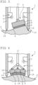
- a device 1 for producing an impression is shown in each case, which is set up on a surface 2 to be impressioned.
- a plunger 4 is mounted displaceably in the direction of the surface 2 in a plunger guide, not shown.
- the pressure die 4 has a blank carrier 5 , whose upper side facing the surface 2 forms a pressure surface 6 .
- On the pressure surface 6 of the blank carrier 5 is an in figure 5 separately shown impression blank 7 fixed by means of a layer of adhesive that can be removed again.
- the impression blank 7 has a dimensionally stable carrier layer 8 and an impression layer 9 made of a curable, crosslinking polymer material applied thereto.
- the impression layer 9 is initially not yet hardened and has pasty properties.
- the pressure stamp 4 can be made from an in 1 shown set-up position, in which the molding blank 7 can be attached to the pressure surface 6 of the blank carrier 5 and the housing 3 can then be positioned on the surface 2, into an in 2 shown pressing position are shifted, in which the plunger 4 is pressed with the impression blank 7 fixed thereto on the surface 2.
- a curing device 12 is arranged in the housing 3 of the device 1 and is supplied with electrical energy and controlled via a control and energy supply device 13 .
- the curing device 12 has a plurality of UV light-emitting diodes 14 arranged concentrically around the pressure plunger 4 on an inner wall of the housing 3 . When switched on, the UV light-emitting diodes 14 emit UV light in the direction of the impression blank 7. The UV light from the UV light-emitting diodes 14 activates and accelerates crosslinking and curing of the hardenable polymer material of the impression layer 9 of the impression blank 7.
- the impression layer 9 that has not yet hardened deforms and forms a matrix or a negative form of the surface topography of the surface 2.
- the UV light-emitting diodes 14 can automatically Relocation of the plunger 4 to the surface 2 or manually by a not shown Turn-on device are turned on to harden the adapted to the surface topography of the surface 2 impression layer 9 and to conserve the impression created thereby permanently.
- the blank carrier 5 can consist of a UV-transparent material, so that the UV radiation emitted by the UV light-emitting diodes can illuminate the impression blank 8 and the impression layer 9 .
- the housing 3 has on a lower housing edge 15 three spaced-apart conically tapering contact points 16.
- the contact points 16 enable the housing 3 to be positioned without tilting on the surface 2 and reduce the risk of an undesired lateral displacement of the housing 3 on the surface 2.
- the blank carrier 5 is pivotably mounted on a linearly displaceable guide rod 17 of the plunger 4 .
- the orientation of the blank carrier 5 can thus be adapted to an uneven or sloping surface 2 in a simple manner.
- the blank carrier 5 three independently pivotally mounted pressure segments 18, which together form the pressure surface 6 of the plunger 4, on which the impression blank 7 can be fixed to with the Plunger 4 to be pressed against the surface 2. Due to the pressure segments 18 that can be displaced relative to one another, the impression layer 9 of the impression blank 7 can also be adapted to a curved surface 2 or to an uneven surface 2 and pressed on with a largely constant contact pressure.
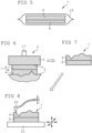
- the molding blank 7 shown separately and in an enlarged view consists of the dimensionally stable carrier layer 8 and the initially still pasty molding layer 9 made of the crosslinking polymer material, which can be cured by UV light.
- the impression blank 7 is a consumable and can be surrounded or packaged in a light-tight and in particular UV-tight cover 19 to protect the impression layer 9 from hardening and damage to the impression blank 7 during its storage before use.
- FIG. 6 to 8 individual method steps are shown as examples and schematically, which can be carried out for a surface analysis using the method according to the invention.
- the impression blank 7 is placed in an in 6 pressed against the surface 2 to be examined in the pressing step shown with the pressure stamp 4, or by the blank carrier 5 of the pressure stamp 4 with the device 1, so that the still deformable material of the impression layer 9 of the impression blank 7 adapts to the surface topography of the surface 2.
- the material of the molding layer 9 is then cured in a molding step by irradiation with UV light.
- detachment of the deformed and solidified impression blank 7 from the surface 2 and then from the blank carrier 5 forms the in 7
- Deformed molding layer 9 shown is a matrix of the surface topography.
- the material of the molding layer 9 can also be influenced by other properties of the surface 2 to be analyzed, such as its magnetic properties, its hydrophobicity or its chemical properties, so that a subsequent analysis of the solidified molding blank 7
- the properties transferred to or acting on the impression blank 7 can be analyzed using suitable measuring methods and measuring devices.
- the analysis of the surface topography using a probe 20 of a scanning probe microscope is shown as an example.
- the hardened impression blank 7 forming the matrix can be arranged on a measuring table 21 of the scanning probe microscope, which is not shown in detail.
- Surfaces 2 that are difficult to access spatially or surfaces 2 that change over time, or surface properties, can also be analyzed reliably and reproducibly with little effort using the impression according to the invention.
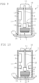
- a force measuring device 22 is arranged on the guide rod 17 in the vicinity of the blank carrier 5 .
- the force-measuring device 22 can contain, for example, a deformation-sensitive piezoelectric element or a strain gauge arrangement. With the force measuring device 22 can during the pressing of the plunger 4 to the surface 2 on the Impression blank 7 exerted contact pressure can be detected. In the same way, the force-measuring device 22 can also be used to record the tensile force that is applied in order to release the hardened impression blank 7, ie the impression produced, from the surface 2 again.
- the force measuring device 22 can be wired or wirelessly connected to an evaluation device, not shown.
- the measurement signals recorded with the force-measuring device 22 can already be evaluated during the creation of the impression and can be used, for example, to generate an optical or acoustic display as soon as sufficient contact pressure has been reached, or if the contact pressure drops excessively or varies during the creation of the impression .
- the measurement signals generated with the force-measuring device 22 can also initially be stored in the evaluation device and kept ready for subsequent evaluation or processing of all information generated about the impression.
- the exemplary embodiment of the device 1 has a conically tapering deformation body 23 which is displaceably mounted in the guide rod 17 or in the blank carrier 5 .
- a displacement device also not shown separately, for example a spring device or an electric motor, can be actuated with an actuating device not shown and the deformation body 23 can be pressed into the surface 2 in order to bring about a change in the topography of the surface 2 .
- the impression blank 7 is ring-shaped designed and surrounds the deformation body 23, which is pressed through a central recess of the impression blank 7 and into the surface 2.
- the exemplary embodiment shown shows the generation of an impression after a previous deformation of the surface 2 with the deformation body 23 as an example.
Landscapes
- Engineering & Computer Science (AREA)
- Mechanical Engineering (AREA)
- Physics & Mathematics (AREA)
- Health & Medical Sciences (AREA)
- General Health & Medical Sciences (AREA)
- General Physics & Mathematics (AREA)
- Nuclear Medicine, Radiotherapy & Molecular Imaging (AREA)
- Radiology & Medical Imaging (AREA)
- Shaping Of Tube Ends By Bending Or Straightening (AREA)
- Casting Or Compression Moulding Of Plastics Or The Like (AREA)
Claims (17)
- Dispositif (1) pour produire une empreinte d'une propriété de surface avec un boîtier (3), avec un vérin presseur (4) monté sur ou dans le boîtier (3), déplaçable et pouvant être pressé contre une surface (2), qui présente un support d'ébauche (5) avec une surface de pression pouvant être pressée contre une surface (2), sur laquelle une ébauche d'empreinte (7) avec une couche d'empreinte (9) en un matériau durcissable peut être fixée de manière amovible, et avec un appareil de durcissement (12) agencé sur ou dans le boîtier (3), avec lequel le matériau durcissable de l'ébauche d'empreinte (7) peut être durci pendant la pression sur la surface (2), caractérisé en ce que le dispositif peut être placé sur une surface dont l'empreinte doit être prise pour produire une empreinte, et en ce que le boîtier est adapté pour une utilisation et une manipulation manuelles.
- Dispositif (1) selon la revendication 1, caractérisé en ce que le support d'ébauche (5) est monté pivotant.
- Dispositif (1) selon la revendication 1 ou la revendication 2, caractérisé en ce que le support d'ébauche (5) présente au moins deux segments de pression (18) déplaçables l'un par rapport à l'autre.
- Dispositif (1) selon l'une quelconque des revendications précédentes, caractérisé en ce que le dispositif (1) présente un appareil de positionnement pour le vérin presseur (4) déplaçable.
- Dispositif (1) selon l'une quelconque des revendications précédentes, caractérisé en ce que le dispositif (1) présente un appareil de mesure de force (22) permettant de détecter une force de traction ou une force de pression exercée sur le vérin presseur.
- Dispositif (1) selon la revendication 5, caractérisé en ce que l'appareil de mesure de force (22) est agencé sur une tige de guidage (17) du vérin presseur (4).
- Dispositif (1) selon l'une quelconque des revendications précédentes, caractérisé en ce que le dispositif présente un corps de déformation (23) monté avec un appareil de déplacement, qui peut être pressé contre la surface (2) par un appareil d'actionnement pour provoquer une déformation de la surface (2).
- Dispositif (1) selon la revendication 7, caractérisé en ce que le corps de déformation (23) est monté dans le support d'ébauche (5) de manière à pouvoir être déplacé entre une position de pression dépassant du support d'ébauche (5) au-dessus de la surface de pression (6) et une position de repos rétractée dans le support d'ébauche (5), ne dépassant pas de la surface de pression (6).
- Dispositif (1) selon l'une quelconque des revendications précédentes, caractérisé en ce que l'appareil de durcissement (12) présente un appareil d'éclairage avec rayonnement électromagnétique.
- Dispositif (1) selon la revendication 9, caractérisé en ce que l'appareil d'éclairage émet un rayonnement UV.
- Dispositif (1) selon l'une quelconque des revendications précédentes, caractérisé en ce que la surface de pression (6) du support d'ébauche (5) présente une couche adhésive pour la fixation amovible de l'ébauche d'empreinte (7).
- Procédé de production d'une empreinte d'une propriété de surface, dans lequel, avec un dispositif décrit dans les revendications 1 à 11, dans une étape de pression, une ébauche d'empreinte (7) avec une couche d'empreinte (9) en un matériau durcissable est fixée sur une surface de pression (6) d'un vérin presseur (4) et est pressée avec le vérin presseur (6) contre une surface (2), dans lequel le matériau durcissable de la couche d'empreinte (9) est durci dans une étape de prise d'empreinte avec un appareil de durcissement (12) pendant la pression, et dans lequel l'ébauche d'empreinte (7) avec l'empreinte durcie de la surface (2) est détachée du vérin presseur (4) dans une étape de retrait.
- Procédé selon la revendication 12, caractérisé en ce que le matériau durcissable de la couche d'empreinte (7) est un polymère réticulant activable par un rayonnement électromagnétique et en ce que, dans l'étape de prise d'empreinte, le polymère réticulant est exposé à un rayonnement électromagnétique avec un appareil d'éclairage.
- Procédé selon la revendication 13, caractérisé en ce que le matériau durcissable de la couche d'empreinte (9) est exposé à un rayonnement UV.
- Procédé selon l'une quelconque des revendications 12 à 14, caractérisé en ce que, pendant l'étape de pression, une force de pression exercée sur le vérin presseur (4) est détectée avec un appareil de mesure de force (22).
- Procédé selon l'une quelconque des revendications 12 à 15, caractérisé en ce qu'une force de traction exercée sur l'ébauche d'empreinte (7) est détectée avec un appareil de mesure de force (22) pendant que l'ébauche d'empreinte (7) est détachée de la surface (2) avec l'empreinte durcie.
- Procédé selon l'une quelconque des revendications 12 à 16, caractérisé en ce qu'avant ou pendant l'étape de prise d'empreinte, un corps de déformation (23) est pressé contre la surface (2) et provoque une déformation de la surface (2), qui est prise d'empreinte par l'ébauche d'empreinte (7).
Applications Claiming Priority (2)
| Application Number | Priority Date | Filing Date | Title |
|---|---|---|---|
| DE102015108327.2A DE102015108327A1 (de) | 2015-05-27 | 2015-05-27 | Vorrichtung und Verfahren zum Erzeugen einer Abformung einer Oberflächeneigenschaft |
| PCT/EP2016/061858 WO2016189064A1 (fr) | 2015-05-27 | 2016-05-25 | Dispositif et procédé pour réaliser un moulage de caractéristiques de surface |
Publications (2)
| Publication Number | Publication Date |
|---|---|
| EP3302913A1 EP3302913A1 (fr) | 2018-04-11 |
| EP3302913B1 true EP3302913B1 (fr) | 2023-06-21 |
Family
ID=56134306
Family Applications (1)
| Application Number | Title | Priority Date | Filing Date |
|---|---|---|---|
| EP16729799.3A Active EP3302913B1 (fr) | 2015-05-27 | 2016-05-25 | Dispositif et procédé pour réaliser un moulage de caractéristiques de surface |
Country Status (5)
| Country | Link |
|---|---|
| US (1) | US11014273B2 (fr) |
| EP (1) | EP3302913B1 (fr) |
| CN (1) | CN107848153B (fr) |
| DE (1) | DE102015108327A1 (fr) |
| WO (1) | WO2016189064A1 (fr) |
Families Citing this family (1)
| Publication number | Priority date | Publication date | Assignee | Title |
|---|---|---|---|---|
| US11813811B2 (en) * | 2019-05-22 | 2023-11-14 | The Boeing Company | Conformable apparatus, systems and methods for treating a composite material |
Family Cites Families (17)
| Publication number | Priority date | Publication date | Assignee | Title |
|---|---|---|---|---|
| US4554036A (en) * | 1984-05-07 | 1985-11-19 | Newsom Cosby M | Portable vacuum device and method of using same |
| US5635660A (en) * | 1989-03-10 | 1997-06-03 | Primex Technologies, Inc. | Sabot segment molding apparatus |
| US6435242B1 (en) * | 1998-03-23 | 2002-08-20 | Northrop Grumman Corp | Repair pressure applicator |
| US6849558B2 (en) * | 2002-05-22 | 2005-02-01 | The Board Of Trustees Of The Leland Stanford Junior University | Replication and transfer of microstructures and nanostructures |
| US6900881B2 (en) * | 2002-07-11 | 2005-05-31 | Molecular Imprints, Inc. | Step and repeat imprint lithography systems |
| DE102004012786A1 (de) * | 2004-03-15 | 2005-09-29 | Newfrey Llc, Newark | Fügevorrichtung zum Befestigen von kleinteiligen Bauelementen an einer Trägerfläche durch Kleben |
| JP2008062486A (ja) | 2006-09-06 | 2008-03-21 | Kyocera Corp | 成形用スタンパおよび成形装置 |
| WO2008126312A1 (fr) * | 2007-03-30 | 2008-10-23 | Pioneer Corporation | Appareil d'impression thermique et procédé d'impression thermique |
| JPWO2008142784A1 (ja) | 2007-05-23 | 2010-08-05 | パイオニア株式会社 | インプリント装置 |
| JP4641552B2 (ja) * | 2008-06-23 | 2011-03-02 | キヤノン株式会社 | 微細加工方法及び微細加工装置 |
| JP2010287829A (ja) * | 2009-06-15 | 2010-12-24 | Asahi Kasei Corp | 微細パタンの製造方法 |
| US8262841B2 (en) * | 2010-11-24 | 2012-09-11 | The Boeing Company | Methods for void-free debulking of adhesive bonded joints |
| JP6061524B2 (ja) | 2011-08-11 | 2017-01-18 | キヤノン株式会社 | インプリント装置および物品の製造方法 |
| JP6112546B2 (ja) * | 2012-12-27 | 2017-04-12 | ダイハツ工業株式会社 | プレス成形金型 |
| US9427911B1 (en) * | 2013-09-30 | 2016-08-30 | The Boeing Company | System and method for forming a bonded joint |
| US9545782B2 (en) * | 2014-05-13 | 2017-01-17 | The Boeing Company | Method and apparatus for repairing composite materials |
| US9782937B1 (en) * | 2014-05-16 | 2017-10-10 | The Boeing Company | Apparatus for forming contoured composite laminates |
-
2015
- 2015-05-27 DE DE102015108327.2A patent/DE102015108327A1/de not_active Withdrawn
-
2016
- 2016-05-25 WO PCT/EP2016/061858 patent/WO2016189064A1/fr not_active Ceased
- 2016-05-25 US US15/576,865 patent/US11014273B2/en active Active
- 2016-05-25 EP EP16729799.3A patent/EP3302913B1/fr active Active
- 2016-05-25 CN CN201680043917.7A patent/CN107848153B/zh active Active
Also Published As
| Publication number | Publication date |
|---|---|
| EP3302913A1 (fr) | 2018-04-11 |
| CN107848153B (zh) | 2021-07-13 |
| US20180169911A1 (en) | 2018-06-21 |
| WO2016189064A1 (fr) | 2016-12-01 |
| DE102015108327A1 (de) | 2016-12-01 |
| US11014273B2 (en) | 2021-05-25 |
| CN107848153A (zh) | 2018-03-27 |
Similar Documents
| Publication | Publication Date | Title |
|---|---|---|
| EP2718094B1 (fr) | Procédé et dispositif pour la détermination de la répartition de la pression pour le collage | |
| DE102008019342A1 (de) | Verfahren und Vorrichtung zur Erzeugung eines Zeichens in einer Werkstückoberfläche durch Prägen | |
| EP3174690A1 (fr) | Dispositif de stéréographie à unité modulaire formant contenant | |
| EP3130885A1 (fr) | Dispositif de balayage, ballonnet pour le fonctionnement d'un dispositif de balayage, procede de fonctionnement d'un dispositif de balayage et programme de commande pour un dispositif de balayage | |
| EP3302913B1 (fr) | Dispositif et procédé pour réaliser un moulage de caractéristiques de surface | |
| DE102008058782A1 (de) | Vorrichtung zur physiologischen, dynamischen in-vitro Zelldehnung | |
| DE102014215213A1 (de) | Stereolithografievorrichtung mit Behälterbaueinheit | |
| DE102014213888A1 (de) | Justiervorrichtung und Justierverfahren | |
| DE102007043364B4 (de) | Halterung zur Aufnahme einer Ultraschallquelle | |
| DE19720864C2 (de) | Verfahren und Vorrichtung zur zerstörungsfreien Bestimmung der Elastizität von Materialien | |
| AT516146A4 (de) | Kalibrierverfahren für eine Biegemaschine | |
| EP3853678A2 (fr) | Procédé de positionnement d'une pièce et dispositif associé | |
| DE102008034136A1 (de) | Verfahren zum Bestimmen einer Eindruckoberfläche | |
| DE102019128423A1 (de) | Lehre zur Anbringung von Bauteilen an einem Kraftfahrzeugträgerteil | |
| DE102016207697B4 (de) | Verfahren zum Verbinden wenigstens zweier Bauteile mittels einer Stanznietvorrichtung, Stanznietvorrichtung und Fertigungseinrichtung | |
| DE102016100707A1 (de) | Messvorrichtung, Messanordnung und Verfahren zur Ermittlung von Messsignalen während einer Eindringbewegung eines Eindringkörpers in eine Oberfläche eines Prüfkörpers | |
| DE102011054438A1 (de) | Verfahren zur Bestimmung des Trocknungsgrades von Druckbögen | |
| Coren et al. | Microcontact printing on metallic surfaces for optical deformation measurements | |
| BE1032743B1 (de) | Belastungsvorrichtung von zellzugkräften | |
| DE102006012374A1 (de) | Kratzvorrichtung | |
| DE202016008320U1 (de) | Stellmechanismus einer Graviermaschine | |
| DE202009006483U1 (de) | Vorrichtung zur Erzeugung eines Zeichens in einer Werkstückoberfläche durch Prägen | |
| DE112007001853T5 (de) | Tampondruck von Videozielobjekten zur Dehnungsmessung | |
| DE4434863A1 (de) | Vorrichtung zur Gewinnung der topographischen Oberflächenbeschaffenheit | |
| DE19814939A1 (de) | Verfahren zum Positionieren von Gravierorganen |
Legal Events
| Date | Code | Title | Description |
|---|---|---|---|
| STAA | Information on the status of an ep patent application or granted ep patent |
Free format text: STATUS: THE INTERNATIONAL PUBLICATION HAS BEEN MADE |
|
| PUAI | Public reference made under article 153(3) epc to a published international application that has entered the european phase |
Free format text: ORIGINAL CODE: 0009012 |
|
| STAA | Information on the status of an ep patent application or granted ep patent |
Free format text: STATUS: REQUEST FOR EXAMINATION WAS MADE |
|
| 17P | Request for examination filed |
Effective date: 20171220 |
|
| AK | Designated contracting states |
Kind code of ref document: A1 Designated state(s): AL AT BE BG CH CY CZ DE DK EE ES FI FR GB GR HR HU IE IS IT LI LT LU LV MC MK MT NL NO PL PT RO RS SE SI SK SM TR |
|
| AX | Request for extension of the european patent |
Extension state: BA ME |
|
| RIN1 | Information on inventor provided before grant (corrected) |
Inventor name: GOLOVKO, DMYTRO Inventor name: HEIM, LARS-OLIVER |
|
| DAV | Request for validation of the european patent (deleted) | ||
| DAX | Request for extension of the european patent (deleted) | ||
| STAA | Information on the status of an ep patent application or granted ep patent |
Free format text: STATUS: EXAMINATION IS IN PROGRESS |
|
| 17Q | First examination report despatched |
Effective date: 20190823 |
|
| GRAP | Despatch of communication of intention to grant a patent |
Free format text: ORIGINAL CODE: EPIDOSNIGR1 |
|
| STAA | Information on the status of an ep patent application or granted ep patent |
Free format text: STATUS: GRANT OF PATENT IS INTENDED |
|
| INTG | Intention to grant announced |
Effective date: 20221223 |
|
| GRAS | Grant fee paid |
Free format text: ORIGINAL CODE: EPIDOSNIGR3 |
|
| GRAA | (expected) grant |
Free format text: ORIGINAL CODE: 0009210 |
|
| STAA | Information on the status of an ep patent application or granted ep patent |
Free format text: STATUS: THE PATENT HAS BEEN GRANTED |
|
| AK | Designated contracting states |
Kind code of ref document: B1 Designated state(s): AL AT BE BG CH CY CZ DE DK EE ES FI FR GB GR HR HU IE IS IT LI LT LU LV MC MK MT NL NO PL PT RO RS SE SI SK SM TR |
|
| REG | Reference to a national code |
Ref country code: CH Ref legal event code: EP |
|
| REG | Reference to a national code |
Ref country code: DE Ref legal event code: R096 Ref document number: 502016015887 Country of ref document: DE |
|
| REG | Reference to a national code |
Ref country code: AT Ref legal event code: REF Ref document number: 1580598 Country of ref document: AT Kind code of ref document: T Effective date: 20230715 |
|
| REG | Reference to a national code |
Ref country code: IE Ref legal event code: FG4D Free format text: LANGUAGE OF EP DOCUMENT: GERMAN |
|
| REG | Reference to a national code |
Ref country code: LT Ref legal event code: MG9D |
|
| REG | Reference to a national code |
Ref country code: NL Ref legal event code: MP Effective date: 20230621 |
|
| PG25 | Lapsed in a contracting state [announced via postgrant information from national office to epo] |
Ref country code: SE Free format text: LAPSE BECAUSE OF FAILURE TO SUBMIT A TRANSLATION OF THE DESCRIPTION OR TO PAY THE FEE WITHIN THE PRESCRIBED TIME-LIMIT Effective date: 20230621 Ref country code: NO Free format text: LAPSE BECAUSE OF FAILURE TO SUBMIT A TRANSLATION OF THE DESCRIPTION OR TO PAY THE FEE WITHIN THE PRESCRIBED TIME-LIMIT Effective date: 20230921 |
|
| PG25 | Lapsed in a contracting state [announced via postgrant information from national office to epo] |
Ref country code: RS Free format text: LAPSE BECAUSE OF FAILURE TO SUBMIT A TRANSLATION OF THE DESCRIPTION OR TO PAY THE FEE WITHIN THE PRESCRIBED TIME-LIMIT Effective date: 20230621 Ref country code: NL Free format text: LAPSE BECAUSE OF FAILURE TO SUBMIT A TRANSLATION OF THE DESCRIPTION OR TO PAY THE FEE WITHIN THE PRESCRIBED TIME-LIMIT Effective date: 20230621 Ref country code: LV Free format text: LAPSE BECAUSE OF FAILURE TO SUBMIT A TRANSLATION OF THE DESCRIPTION OR TO PAY THE FEE WITHIN THE PRESCRIBED TIME-LIMIT Effective date: 20230621 Ref country code: LT Free format text: LAPSE BECAUSE OF FAILURE TO SUBMIT A TRANSLATION OF THE DESCRIPTION OR TO PAY THE FEE WITHIN THE PRESCRIBED TIME-LIMIT Effective date: 20230621 Ref country code: HR Free format text: LAPSE BECAUSE OF FAILURE TO SUBMIT A TRANSLATION OF THE DESCRIPTION OR TO PAY THE FEE WITHIN THE PRESCRIBED TIME-LIMIT Effective date: 20230621 Ref country code: GR Free format text: LAPSE BECAUSE OF FAILURE TO SUBMIT A TRANSLATION OF THE DESCRIPTION OR TO PAY THE FEE WITHIN THE PRESCRIBED TIME-LIMIT Effective date: 20230922 |
|
| PG25 | Lapsed in a contracting state [announced via postgrant information from national office to epo] |
Ref country code: FI Free format text: LAPSE BECAUSE OF FAILURE TO SUBMIT A TRANSLATION OF THE DESCRIPTION OR TO PAY THE FEE WITHIN THE PRESCRIBED TIME-LIMIT Effective date: 20230621 |
|
| PG25 | Lapsed in a contracting state [announced via postgrant information from national office to epo] |
Ref country code: SK Free format text: LAPSE BECAUSE OF FAILURE TO SUBMIT A TRANSLATION OF THE DESCRIPTION OR TO PAY THE FEE WITHIN THE PRESCRIBED TIME-LIMIT Effective date: 20230621 |
|
| PG25 | Lapsed in a contracting state [announced via postgrant information from national office to epo] |
Ref country code: ES Free format text: LAPSE BECAUSE OF FAILURE TO SUBMIT A TRANSLATION OF THE DESCRIPTION OR TO PAY THE FEE WITHIN THE PRESCRIBED TIME-LIMIT Effective date: 20230621 |
|
| PG25 | Lapsed in a contracting state [announced via postgrant information from national office to epo] |
Ref country code: IS Free format text: LAPSE BECAUSE OF FAILURE TO SUBMIT A TRANSLATION OF THE DESCRIPTION OR TO PAY THE FEE WITHIN THE PRESCRIBED TIME-LIMIT Effective date: 20231021 |
|
| PG25 | Lapsed in a contracting state [announced via postgrant information from national office to epo] |
Ref country code: SM Free format text: LAPSE BECAUSE OF FAILURE TO SUBMIT A TRANSLATION OF THE DESCRIPTION OR TO PAY THE FEE WITHIN THE PRESCRIBED TIME-LIMIT Effective date: 20230621 Ref country code: SK Free format text: LAPSE BECAUSE OF FAILURE TO SUBMIT A TRANSLATION OF THE DESCRIPTION OR TO PAY THE FEE WITHIN THE PRESCRIBED TIME-LIMIT Effective date: 20230621 Ref country code: RO Free format text: LAPSE BECAUSE OF FAILURE TO SUBMIT A TRANSLATION OF THE DESCRIPTION OR TO PAY THE FEE WITHIN THE PRESCRIBED TIME-LIMIT Effective date: 20230621 Ref country code: PT Free format text: LAPSE BECAUSE OF FAILURE TO SUBMIT A TRANSLATION OF THE DESCRIPTION OR TO PAY THE FEE WITHIN THE PRESCRIBED TIME-LIMIT Effective date: 20231023 Ref country code: IS Free format text: LAPSE BECAUSE OF FAILURE TO SUBMIT A TRANSLATION OF THE DESCRIPTION OR TO PAY THE FEE WITHIN THE PRESCRIBED TIME-LIMIT Effective date: 20231021 Ref country code: ES Free format text: LAPSE BECAUSE OF FAILURE TO SUBMIT A TRANSLATION OF THE DESCRIPTION OR TO PAY THE FEE WITHIN THE PRESCRIBED TIME-LIMIT Effective date: 20230621 Ref country code: EE Free format text: LAPSE BECAUSE OF FAILURE TO SUBMIT A TRANSLATION OF THE DESCRIPTION OR TO PAY THE FEE WITHIN THE PRESCRIBED TIME-LIMIT Effective date: 20230621 Ref country code: CZ Free format text: LAPSE BECAUSE OF FAILURE TO SUBMIT A TRANSLATION OF THE DESCRIPTION OR TO PAY THE FEE WITHIN THE PRESCRIBED TIME-LIMIT Effective date: 20230621 |
|
| PG25 | Lapsed in a contracting state [announced via postgrant information from national office to epo] |
Ref country code: PL Free format text: LAPSE BECAUSE OF FAILURE TO SUBMIT A TRANSLATION OF THE DESCRIPTION OR TO PAY THE FEE WITHIN THE PRESCRIBED TIME-LIMIT Effective date: 20230621 |
|
| REG | Reference to a national code |
Ref country code: DE Ref legal event code: R097 Ref document number: 502016015887 Country of ref document: DE |
|
| PLBE | No opposition filed within time limit |
Free format text: ORIGINAL CODE: 0009261 |
|
| STAA | Information on the status of an ep patent application or granted ep patent |
Free format text: STATUS: NO OPPOSITION FILED WITHIN TIME LIMIT |
|
| PG25 | Lapsed in a contracting state [announced via postgrant information from national office to epo] |
Ref country code: DK Free format text: LAPSE BECAUSE OF FAILURE TO SUBMIT A TRANSLATION OF THE DESCRIPTION OR TO PAY THE FEE WITHIN THE PRESCRIBED TIME-LIMIT Effective date: 20230621 |
|
| PG25 | Lapsed in a contracting state [announced via postgrant information from national office to epo] |
Ref country code: SI Free format text: LAPSE BECAUSE OF FAILURE TO SUBMIT A TRANSLATION OF THE DESCRIPTION OR TO PAY THE FEE WITHIN THE PRESCRIBED TIME-LIMIT Effective date: 20230621 |
|
| 26N | No opposition filed |
Effective date: 20240322 |
|
| PG25 | Lapsed in a contracting state [announced via postgrant information from national office to epo] |
Ref country code: SI Free format text: LAPSE BECAUSE OF FAILURE TO SUBMIT A TRANSLATION OF THE DESCRIPTION OR TO PAY THE FEE WITHIN THE PRESCRIBED TIME-LIMIT Effective date: 20230621 Ref country code: IT Free format text: LAPSE BECAUSE OF FAILURE TO SUBMIT A TRANSLATION OF THE DESCRIPTION OR TO PAY THE FEE WITHIN THE PRESCRIBED TIME-LIMIT Effective date: 20230621 |
|
| PG25 | Lapsed in a contracting state [announced via postgrant information from national office to epo] |
Ref country code: BG Free format text: LAPSE BECAUSE OF FAILURE TO SUBMIT A TRANSLATION OF THE DESCRIPTION OR TO PAY THE FEE WITHIN THE PRESCRIBED TIME-LIMIT Effective date: 20230621 |
|
| PG25 | Lapsed in a contracting state [announced via postgrant information from national office to epo] |
Ref country code: BG Free format text: LAPSE BECAUSE OF FAILURE TO SUBMIT A TRANSLATION OF THE DESCRIPTION OR TO PAY THE FEE WITHIN THE PRESCRIBED TIME-LIMIT Effective date: 20230621 |
|
| REG | Reference to a national code |
Ref country code: CH Ref legal event code: PL |
|
| PG25 | Lapsed in a contracting state [announced via postgrant information from national office to epo] |
Ref country code: MC Free format text: LAPSE BECAUSE OF FAILURE TO SUBMIT A TRANSLATION OF THE DESCRIPTION OR TO PAY THE FEE WITHIN THE PRESCRIBED TIME-LIMIT Effective date: 20230621 |
|
| PG25 | Lapsed in a contracting state [announced via postgrant information from national office to epo] |
Ref country code: LU Free format text: LAPSE BECAUSE OF NON-PAYMENT OF DUE FEES Effective date: 20240525 |
|
| GBPC | Gb: european patent ceased through non-payment of renewal fee |
Effective date: 20240525 |
|
| PG25 | Lapsed in a contracting state [announced via postgrant information from national office to epo] |
Ref country code: MC Free format text: LAPSE BECAUSE OF FAILURE TO SUBMIT A TRANSLATION OF THE DESCRIPTION OR TO PAY THE FEE WITHIN THE PRESCRIBED TIME-LIMIT Effective date: 20230621 Ref country code: LU Free format text: LAPSE BECAUSE OF NON-PAYMENT OF DUE FEES Effective date: 20240525 Ref country code: CH Free format text: LAPSE BECAUSE OF NON-PAYMENT OF DUE FEES Effective date: 20240531 |
|
| REG | Reference to a national code |
Ref country code: BE Ref legal event code: MM Effective date: 20240531 |
|
| PG25 | Lapsed in a contracting state [announced via postgrant information from national office to epo] |
Ref country code: IE Free format text: LAPSE BECAUSE OF NON-PAYMENT OF DUE FEES Effective date: 20240525 |
|
| PG25 | Lapsed in a contracting state [announced via postgrant information from national office to epo] |
Ref country code: BE Free format text: LAPSE BECAUSE OF NON-PAYMENT OF DUE FEES Effective date: 20240531 |
|
| PG25 | Lapsed in a contracting state [announced via postgrant information from national office to epo] |
Ref country code: FR Free format text: LAPSE BECAUSE OF NON-PAYMENT OF DUE FEES Effective date: 20240531 |
|
| PG25 | Lapsed in a contracting state [announced via postgrant information from national office to epo] |
Ref country code: GB Free format text: LAPSE BECAUSE OF NON-PAYMENT OF DUE FEES Effective date: 20240525 |
|
| PGFP | Annual fee paid to national office [announced via postgrant information from national office to epo] |
Ref country code: DE Payment date: 20250519 Year of fee payment: 10 |
|
| REG | Reference to a national code |
Ref country code: AT Ref legal event code: MM01 Ref document number: 1580598 Country of ref document: AT Kind code of ref document: T Effective date: 20240525 |
|
| PG25 | Lapsed in a contracting state [announced via postgrant information from national office to epo] |
Ref country code: AT Free format text: LAPSE BECAUSE OF NON-PAYMENT OF DUE FEES Effective date: 20240525 |
|
| PG25 | Lapsed in a contracting state [announced via postgrant information from national office to epo] |
Ref country code: HU Free format text: LAPSE BECAUSE OF FAILURE TO SUBMIT A TRANSLATION OF THE DESCRIPTION OR TO PAY THE FEE WITHIN THE PRESCRIBED TIME-LIMIT; INVALID AB INITIO Effective date: 20160525 |
|
| PG25 | Lapsed in a contracting state [announced via postgrant information from national office to epo] |
Ref country code: CY Free format text: LAPSE BECAUSE OF FAILURE TO SUBMIT A TRANSLATION OF THE DESCRIPTION OR TO PAY THE FEE WITHIN THE PRESCRIBED TIME-LIMIT; INVALID AB INITIO Effective date: 20160525 |