EP3302966B1 - Verbundglasscheibe - Google Patents
Verbundglasscheibe Download PDFInfo
- Publication number
- EP3302966B1 EP3302966B1 EP16727780.5A EP16727780A EP3302966B1 EP 3302966 B1 EP3302966 B1 EP 3302966B1 EP 16727780 A EP16727780 A EP 16727780A EP 3302966 B1 EP3302966 B1 EP 3302966B1
- Authority
- EP
- European Patent Office
- Prior art keywords
- busbar
- ply
- glazing
- film
- laminated glazing
- Prior art date
- Legal status (The legal status is an assumption and is not a legal conclusion. Google has not performed a legal analysis and makes no representation as to the accuracy of the status listed.)
- Active
Links
Images


Classifications
-
- C—CHEMISTRY; METALLURGY
- C03—GLASS; MINERAL OR SLAG WOOL
- C03C—CHEMICAL COMPOSITION OF GLASSES, GLAZES OR VITREOUS ENAMELS; SURFACE TREATMENT OF GLASS; SURFACE TREATMENT OF FIBRES OR FILAMENTS MADE FROM GLASS, MINERALS OR SLAGS; JOINING GLASS TO GLASS OR OTHER MATERIALS
- C03C27/00—Joining pieces of glass to pieces of other inorganic material; Joining glass to glass other than by fusing
- C03C27/06—Joining glass to glass by processes other than fusing
- C03C27/10—Joining glass to glass by processes other than fusing with the aid of adhesive specially adapted for that purpose
-
- B—PERFORMING OPERATIONS; TRANSPORTING
- B32—LAYERED PRODUCTS
- B32B—LAYERED PRODUCTS, i.e. PRODUCTS BUILT-UP OF STRATA OF FLAT OR NON-FLAT, e.g. CELLULAR OR HONEYCOMB, FORM
- B32B17/00—Layered products essentially comprising sheet glass, or glass, slag, or like fibres
- B32B17/06—Layered products essentially comprising sheet glass, or glass, slag, or like fibres comprising glass as the main or only constituent of a layer, next to another layer of a specific material
- B32B17/10—Layered products essentially comprising sheet glass, or glass, slag, or like fibres comprising glass as the main or only constituent of a layer, next to another layer of a specific material of synthetic resin
- B32B17/10005—Layered products essentially comprising sheet glass, or glass, slag, or like fibres comprising glass as the main or only constituent of a layer, next to another layer of a specific material of synthetic resin laminated safety glass or glazing
- B32B17/10009—Layered products essentially comprising sheet glass, or glass, slag, or like fibres comprising glass as the main or only constituent of a layer, next to another layer of a specific material of synthetic resin laminated safety glass or glazing characterized by the number, the constitution or treatment of glass sheets
- B32B17/10036—Layered products essentially comprising sheet glass, or glass, slag, or like fibres comprising glass as the main or only constituent of a layer, next to another layer of a specific material of synthetic resin laminated safety glass or glazing characterized by the number, the constitution or treatment of glass sheets comprising two outer glass sheets
-
- B—PERFORMING OPERATIONS; TRANSPORTING
- B32—LAYERED PRODUCTS
- B32B—LAYERED PRODUCTS, i.e. PRODUCTS BUILT-UP OF STRATA OF FLAT OR NON-FLAT, e.g. CELLULAR OR HONEYCOMB, FORM
- B32B17/00—Layered products essentially comprising sheet glass, or glass, slag, or like fibres
- B32B17/06—Layered products essentially comprising sheet glass, or glass, slag, or like fibres comprising glass as the main or only constituent of a layer, next to another layer of a specific material
- B32B17/10—Layered products essentially comprising sheet glass, or glass, slag, or like fibres comprising glass as the main or only constituent of a layer, next to another layer of a specific material of synthetic resin
- B32B17/10005—Layered products essentially comprising sheet glass, or glass, slag, or like fibres comprising glass as the main or only constituent of a layer, next to another layer of a specific material of synthetic resin laminated safety glass or glazing
- B32B17/10165—Functional features of the laminated safety glass or glazing
- B32B17/10174—Coatings of a metallic or dielectric material on a constituent layer of glass or polymer
- B32B17/1022—Metallic coatings
-
- B—PERFORMING OPERATIONS; TRANSPORTING
- B32—LAYERED PRODUCTS
- B32B—LAYERED PRODUCTS, i.e. PRODUCTS BUILT-UP OF STRATA OF FLAT OR NON-FLAT, e.g. CELLULAR OR HONEYCOMB, FORM
- B32B17/00—Layered products essentially comprising sheet glass, or glass, slag, or like fibres
- B32B17/06—Layered products essentially comprising sheet glass, or glass, slag, or like fibres comprising glass as the main or only constituent of a layer, next to another layer of a specific material
- B32B17/10—Layered products essentially comprising sheet glass, or glass, slag, or like fibres comprising glass as the main or only constituent of a layer, next to another layer of a specific material of synthetic resin
- B32B17/10005—Layered products essentially comprising sheet glass, or glass, slag, or like fibres comprising glass as the main or only constituent of a layer, next to another layer of a specific material of synthetic resin laminated safety glass or glazing
- B32B17/1055—Layered products essentially comprising sheet glass, or glass, slag, or like fibres comprising glass as the main or only constituent of a layer, next to another layer of a specific material of synthetic resin laminated safety glass or glazing characterized by the resin layer, i.e. interlayer
- B32B17/10761—Layered products essentially comprising sheet glass, or glass, slag, or like fibres comprising glass as the main or only constituent of a layer, next to another layer of a specific material of synthetic resin laminated safety glass or glazing characterized by the resin layer, i.e. interlayer containing vinyl acetal
-
- H—ELECTRICITY
- H05—ELECTRIC TECHNIQUES NOT OTHERWISE PROVIDED FOR
- H05B—ELECTRIC HEATING; ELECTRIC LIGHT SOURCES NOT OTHERWISE PROVIDED FOR; CIRCUIT ARRANGEMENTS FOR ELECTRIC LIGHT SOURCES, IN GENERAL
- H05B3/00—Ohmic-resistance heating
- H05B3/84—Heating arrangements specially adapted for transparent or reflecting areas, e.g. for demisting or de-icing windows, mirrors or vehicle windshields
-
- B—PERFORMING OPERATIONS; TRANSPORTING
- B32—LAYERED PRODUCTS
- B32B—LAYERED PRODUCTS, i.e. PRODUCTS BUILT-UP OF STRATA OF FLAT OR NON-FLAT, e.g. CELLULAR OR HONEYCOMB, FORM
- B32B2367/00—Polyesters, e.g. PET, i.e. polyethylene terephthalate
-
- H—ELECTRICITY
- H05—ELECTRIC TECHNIQUES NOT OTHERWISE PROVIDED FOR
- H05B—ELECTRIC HEATING; ELECTRIC LIGHT SOURCES NOT OTHERWISE PROVIDED FOR; CIRCUIT ARRANGEMENTS FOR ELECTRIC LIGHT SOURCES, IN GENERAL
- H05B2203/00—Aspects relating to Ohmic resistive heating covered by group H05B3/00
- H05B2203/011—Heaters using laterally extending conductive material as connecting means
Definitions
- the present invention relates to laminated glazing and to methods for manufacturing laminated glazings.
- Laminated glazings comprising two or more sheets of glazing material, especially glass, bonded together using bonding polymers and having an interlayer functional film are known.
- Such functional films may be used to provide beneficial properties to the glazing such as solar control properties, heatability or increased safety.
- the functional film may be provided with a thin coating comprising a silver layer embedded between two dielectric layers.
- a problem that may arise when providing a functional film in a laminated glazing is distortion or wrinkling of the functional film as a result of the application of vacuum, pressure and heating during the lamination process since lamination usually involves heating the plies of the laminate in an autoclave to a temperature at which the bonding polymer softens and can flow to form a transparent clear film. This problem may be particularly difficult for curved laminated glazings (such as automotive windshields) where the tendency to form a laminate having a wrinkled appearance may be greater.
- WO-A-2001/051279 discloses laminated glass panes which incorporate a transparent functional film embedded between the laminating layers and methods for the manufacture of such panes and solves the problem of wrinkle formation by arranging the film so that it is not co-extensive with the glazing material plies.
- US-A-4,361,751 discloses electrical busbars and more particularly flexible busbars designed to flex at the edge of the window for connection to the power supply.
- US-B-6,242,088 discloses a bi-axially stretched carrier film co-extensive with plies of glazing materials and having a heat shrinkage coefficient in a particular range.
- GB-A-2,381,179 discloses a laminated glazing comprising a first and second ply of glazing material, a conductive coating which may be formed by coating a surface of a resin film (e.g., polyethylene terephthalate), a first busbar in electrical contact with the electrically conductive coating and an uncoated transmission window.
- a resin film e.g., polyethylene terephthalate
- busbars which are in electrical contact with an electrically conductive coating on the film and serve to connect the electrically conductive coating to the power supply, may also give rise to wrinkling effects, especially after lamination.
- wrinkles in the coated film may cause damage in the form of cracks in the electrically conductive coating which (depending on the direction and position of the wrinkles) may result in hot and/or cold spots forming during electrical powering of the circuit. Such damage may cause premature failure of the part.
- a laminated glazing comprising, a first ply of a glazing material, a second ply of a glazing material, a film having an electrically conductive coating, the film being located between the first ply and the second ply, wherein the film comprises polyethylene terephthalate (PET), and a first busbar in electrical contact with the electrically conductive coating, characterised in that the first busbar comprises an expansion portion, the expansion portion comprising a bridging busbar portion not in direct contact with the film or a gap in the first busbar, and wherein the film comprises a cut-out portion wherein the cut-out portion is located at the expansion portion.
- PET polyethylene terephthalate
- Laminated glazings according to the invention are advantageous because wrinkling, especially in the general area of the busbar is prevented or much reduced, which reduces the chances of hot or cold spots and, therefore, the premature failure of such a laminated glazing.
- the use of an expansion portion appears to reduce the effect of the relative movement of the busbar, film and other components of the laminated glazing (many or all of which have different thermal expansion characteristics) during the autoclave process, thus reducing wrinkling.
- the laminated glazing will further comprise a second busbar in electrical contact with the electrically conductive coating.
- the first, and optionally, the second, busbar preferably comprise metal foil.
- the metal foil is preferably copper foil, more preferably tinned copper foil.
- the film comprises PET. This is advantageous because PET films may be conveniently coated, especially by sputtering.
- the electrically conductive coating preferably has a good electrical conductivity.
- the coating will comprise one or more layers of a metal, preferably silver, sandwiched between metal oxide (or other dielectric) layers.
- metal oxide or other dielectric layers.
- the metal oxide layers may comprise, for example, indium oxide, tin oxide, zinc oxide, aluminium oxide or a mixed metal oxide of, for example, zinc/tin oxide.
- the laminated glazing preferably further comprises at least one polymer ply, and preferably at least two polymer plies, located between the first ply and the second ply, the at least one polymer ply, and preferably at least two polymer plies, being in contact with the film.
- the laminated glazing comprises a first polymer ply and a second polymer ply each located between the first ply of a glazing material and the second ply of a glazing material, the first polymer ply and the second polymer ply being in contact with each respective surface of the film (i.e. sandwiching the film between them).
- the, or each, polymer ply comprises polyvinyl butyral (PVB) which is advantageous because it exhibits good adhesion after lamination to both glazing materials (especially glass) and film (especially PET).
- PVB polyvinyl butyral
- the polymer plies are placed on either side of the film to ensure good adhesion to both glazing material (especially glass) plies, thereby holding the laminated glazing together after lamination.
- the first busbar comprises tab portions on each side of the expansion portion. Tab portions are usually wider portions of the busbar, which tend to reduce still further wrinkling effects around the expansion portion.
- the expansion portion may comprise an expansion joint.
- the expansion joint comprises at least one bridging busbar portion.
- the bridging busbar portion may be a piece of busbar material (e.g. metal, preferably copper foil and more preferably tinned copper foil) adhered to either part of the first busbar across a gap in the busbar in the expansion portion. Adhesion of the bridging busbar portion may be by solder or an adhesive as long as there is electrical contact between the bridging busbar portion and each part of the first busbar across the gap.
- the bridging busbar portion may be formed of the same material and may be substantially continuous with the rest of the first busbar.
- the first busbar and the bridging busbar portion may be formed of a strip of conductive material, preferably a single strip of conductive material and more preferably the same strip of conductive material.
- the bridging busbar portion is not in direct contact with the film to further reduce the wrinkling effect.
- the bridging busbar portion will have less mechanical strength than the first busbar so that the bridging busbar portion is more likely than the first busbar to distort during e.g. the lamination process.
- This may be achieved by, for example, the bridging busbar portion having a narrower width than the first busbar and/or having a lower thickness than the first busbar.
- a busbar size may be 10 mm wide ⁇ 100 ⁇ m thick
- the bridging busbar portion may be two pieces of size 4 mm wide (total 8 mm wide) ⁇ 100 ⁇ m thick. It is preferable that the bridging busbar portion is not too thin nor too narrow to ensure that it has sufficient electrical conductivity to reduce the chance of a hotspot occurring.
- the bridging busbar portion will comprise at least one bend and more usually at least two bends.
- the bend or bends of the bridging busbar portion may be of relatively wide curvature (so that at least a portion the bridging busbar portion may be generally S-shaped or sinusoidal) or the bend or bends of the bridging busbar portion may be of relatively narrow curvature so that at least a portion of the bridging busbar portion is angular.
- the expansion portion may comprise a gap in the first busbar.
- the first busbar may be a split busbar comprising two parts with the split/gap occurring at the expansion portion.
- the gap may usually be narrow for example, in the range 5 mm to 20 mm, preferably 7 mm to 15 mm, more preferably 9 mm to 13 mm.
- the first busbar comprises tab portions on each side of the gap.
- the tab portions may comprise electrical connectors, enabling a twin cable to connect to, and thus supply voltage and current, to the adjacent electrical connection ports.
- the film comprises a cut-out portion that is located at the expansion portion, and is preferably substantially co-extensive with the expansion portion.
- the cut-out portion has rounded sides to reduce the chance of wrinkles being caused by corners around the cut-out.
- the great benefit of the cut-out is that if there are, unusually, any distortions in the busbar at or around the expansion portion this does not significantly affect the film because the distortion would be in the region of the cut-out.
- small deformations may be observed in the bridging busbar portion (the bridging busbar portion may be soldered to two tabs on each busbar part) but this would not cause wrinkles in the film because it would occur in the area of the cut-out.
- the effect of a bridging busbar portion in the case where it is of lower mechanical strength than the first busbar is to provide a weaker portion so that any relative movement or creases in the first busbar tends to occur in this portion.
- the first busbar (and/or second busbar if present) may be formed by generally any suitable method, for example, laser cutting. However, the first busbar (and/or second busbar if present) is preferably pre-formed by stamping. Even more preferably the busbar(s) is/are formed by stamping out metal foil provided with an adhesive layer. Usually, the first (and second) busbar has a thickness in the range 50 ⁇ m to 150 ⁇ m, and usually has a width in the range 3 mm to 15 mm.
- the glazing may further comprise an obscuration band on the first ply and/or on the second ply of glazing material. This is advantageous because it may be adapted to obscure the busbar and expansion portion, and the optional cut-out, when the laminated glazing is installed and in use.
- the laminated glazing may be made by a lamination process using high pressure and elevated temperature, e.g. in an autoclave.
- the present invention accordingly provides, a method for manufacturing a laminated glazing, the method comprising
- the method preferably further comprises providing at least one polymer ply (and more preferably at least two polymer plies) located between the first ply of a glazing material and the second ply of a glazing material, the at least one polymer ply being in contact with the film.
- the method further comprises: b1) providing a first polymer ply and a second polymer ply each located between the first ply of a glazing material and the second ply of a glazing material, the first polymer ply and the second polymer ply being in contact with each respective surface of the film.
- Figure 1 shows a reference laminated glazing 10.
- the laminated glazing 10 as shown is an automotive glazing in the form of a windscreen.
- Other types of laminated glazing include automotive side windows, rear windows and/or roof windows or architectural laminated glazings.
- the laminated glazing 10 comprises an electrically conductive portion 15, to which electrical connection is made by a lower (referring to the orientation in the Figures and as the laminated glazing would be orientated in use), first busbar 41 and an upper, second busbar 42.
- First busbar 41 comprises an expansion portion 61 in the form of a gap in first busbar 41, so that first busbar 41 is a split busbar 41.
- the construction of the laminated glazing 10 is more clearly seen in Figure 2 , which is a cross-sectional view on A-A of Figure 1 through the expansion portion 61.
- the laminated glazing 10 comprises a first ply of glazing material 11 and a second ply of glazing material 12.
- the plies of glazing material 11, 12 may be annealed glass or toughened glass.
- the glass composition may be soda-lime glass, usually made by the float glass production process.
- a film 31 is located between the first 11 and second 12 plies of glazing material.
- the film 31 is of polyethylene terephthalate (PET), of a thickness generally in the range 30 ⁇ m to 70 ⁇ m, usually about 50 ⁇ m.
- the film 31 has an electrically conductive coating 32 on at least one surface.
- the electrically conductive coating 32 generally comprises one, two or three silver layers, with one or more dielectric layers of indium oxide between each silver layer.
- the film 31 is sandwiched between a first polymer ply 21 and a second polymer ply 22.
- the polymer plies 21, 22 are preferably of polyvinyl butyral (PVB) or other polymer which provides good adhesion to both the glazing plies 11, 12 (especially to glass plies) and to the film 31 (especially to PET).
- the PVB polymer ply 22 may be an acoustic PVB or a wedged acoustic PVB.
- the first busbar 41 and the second busbar 42 are both arranged so as to be in electrical contact with the electrically conductive coating 32.
- the busbars 41, 42 are usually designed so as to have a low electrical resistance in order that a voltage applied from an external circuit is substantially the same along the length of either busbar 41, 42.
- the busbars 41, 42 may be made of a metal foil, preferably copper foil which may be tinned. Copper foil is particularly advantageous because of copper's low electrical resistivity.
- the busbars 41, 42 will usually have a thickness in the range 50 ⁇ m to 150 ⁇ m, with a preferred thickness of about 100 ⁇ m.
- the busbars 41, 42 will usually have a width in the range 3 mm to 15 mm, preferably about 10 mm.
- a split busbar 41 as shown in Figures 1 and 2 is greatly advantageous because it, surprisingly, reduces wrinkles in the film 31 which previously have been a problem after glazings have been laminated.
- Figure 3 and Figure 4 (which is a cross-sectional view on A-A of Figure 3 , through the expansion portion 61) shows a laminated glazing 10 according to one embodiment of the invention.
- the laminated glazing 10 as shown in Figure 3 and Figure 4 is generally similar to that illustrated in Figure 1 and Figure 2 and the features that are the same are not described below in detail.
- the laminated glazing 10 of Figures 3 and 4 differs from that of Figures 1 and 2 in that the laminated glazing 10 of Figures 3 and 4 , has a cut-out 71 in the film 31, the cut-out 71 being located at the expansion portion 61.
- the use of a cut-out 71 is greatly advantageous because, surprisingly, the cut-out 71 reduces hotspots around the ends of the expansion portion 61 in the first busbar 41.
- the cut-out 71 is a cut portion of the film 31, preferably with rounded edges, in the location of the expansion portion 61 and substantially co-extensive with the expansion portion 61.
- the ends of the split of the first busbar 41 at the expansion portion 61 may each have an electrical connection port so that, for example, a twin cable (or e.g. a multicore cable with two ferrules) can be used to connect to, and thus supply voltage and current, to the adjacent electrical connection ports.
- a twin cable or e.g. a multicore cable with two ferrules
- FIG. 5 and Figure 6 (which is a cross-sectional view on A-A of Figure 5 , through the expansion portion 61) shows a laminated glazing 10 according to another embodiment of the invention.
- the laminated glazing 10 as shown in Figure 5 and Figure 6 is generally similar to that illustrated in Figures 1, 2 , 3 and 4 and the features that are the same will not be described in detail.
- the laminated glazing 10 of Figures 5 and 6 differs from that of Figures 3 and 4 in that the expansion portion 61 of the first busbar 41 is in the form of an expansion joint, with a bridging busbar portion 81 soldered to the ends of the first, split busbar 41 on the inside (i.e. towards the centre of the laminated glazing 10) of the first busbar 41.
- the benefit of the bridging busbar portion 81 is that a single electrical connector can be positioned anywhere along the split busbar 41 and can supply electrical power to the whole busbar 41.
- the bridging busbar portion 81 is of a lower width that the first busbar 41 or second busbar 41, having a total width of about 8 mm (two parts each of 4 mm width).
- Figure 7 and Figure 8 (which is a cross-sectional view on A-A of Figure 7 , through the expansion portion 61) shows a laminated glazing 10 according to a further embodiment of the invention.
- the laminated glazing 10 as shown in Figure 7 and Figure 8 is generally similar to that illustrated in Figures 5 and 6 and the features that are the same will not be described in detail.
- the laminated glazing 10 of Figures 7 and 8 differs from that of Figures 5 and 6 in that the expansion portion 61 is in the form of an expansion joint with the bridging busbar portion 81 outside of the first busbar 41 (i.e. towards the lower edge of the laminated glazing 10).
- the first busbar 41 is situated inwardly (i.e. more toward the centre) of the laminated glazing 10.
- the arrangement of Figures 7 and 8 is advantageous because locating the bridging busbar portion 81 outwardly of the first busbar 41 enables the cut-out 71 of the film 31 to be smaller.
- Figure 9 and Figure 10 (which is a cross-sectional view on A-A of Figure 9 , through the expansion portion 61) shows a laminated glazing 10 according to a still further embodiment of the invention.
- the laminated glazing 10 as shown in Figure 9 and Figure 10 is generally similar to that illustrated in Figures 7 and 8 and the features that are the same will not be described in detail.
- the laminated glazing 10 of Figures 9 and 10 differs from that of Figures 7 and 8 in that an first obscuration band 91 is printed and fired on to the first ply of glazing material 11 before lamination and in that a second obscuration band 92 is printed and fired on to the second ply of glazing material 12 before lamination.
- the obscuration bands 91, 92 are advantageous in that the expansion portion 61 and cut-out 71 are thereby obscured from view when the laminated glazing is mounted and in use.
- Figure 11 shows a yet further embodiment of the present invention, in which a laminated glazing 110 generally of the form of a vehicle windscreen, comprises an electrically conductive portion to which electrical connection is made by a lower, first busbar 41 and an upper, second busbar 42.
- First busbar 41 comprises an expansion portion 61 in the form of an expansion joint toward the centre of the first busbar 41, so that first busbar 41 is in the form of a split busbar 41 with a bridging busbar portion 81 soldered to the adjacent ends of the split first busbar 41.
- the first part of the split first busbar 41 has a first tab portion 62.
- the second part of the split first busbar 41 has a second tab portion 64.
- the first tab portion 62 and second tab portion 64 are enlarged portions at the ends of the busbar which reduce the wrinkling effect on the film 31 laminated between the first and second glazing plies and to which the bridging busbar portion 81 is soldered.
- the expansion portion 61 in the first busbar 41 is located, and generally co-extensive with, a cut-out 71 in the film 31 laminated between the first and second plies of glazing material, the film 31 carrying an electrically conductive coating 32.
- Upper second busbar 42 also has an expansion portion 104 in the form of a gap in the second busbar 42 so that the second busbar 42 is a split second busbar 42.
- a cut-out portion 102 of the film 31 is generally located with, and generally co-extensive with, the second busbar expansion portion 104.
- the laminated glazing 110 has an electrical supply connector 66 which provides electrical power to the first busbar 41 and second busbar 42 from the vehicle electrical system (not shown).
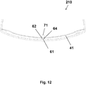
- Figure 12 shows the lower portion of a laminated glazing 210 of a vehicle windscreen.
- a first busbar 41 comprises an expansion portion 61 in the form of a gap, thus the first busbar 41 is in the form of a split first busbar 41.
- the first part of the split first busbar 41 has a first tab portion 62.
- the second part of the split first busbar 41 has a second tab portion 64.
- the first tab portion 62 and second tab portion 64 are enlarged portions at the ends of the busbar which reduce the wrinkling effect on the film 31 laminated between the first and second glazing plies.
- the first tab portion 62 and second tab portion 64 may also each incorporate tab electrical connectors (not shown).
- the cut-out 71 of the film 31 is located at the expansion portion 61.
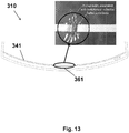
- Figure 13 shows the lower portion of a comparative laminated glazing 310 having a first busbar 341.
- the centre portion 361 of the first busbar 341 was photographed (inset) and as can been seen, the film laminated in the centre of the laminated glazing 310 is severely wrinkled. This can be problematic because such wrinkling can lead to cracks in the electrically conductive coating on the film which may result in cold and/or hot spots (depending on the direction and position of the wrinkles) during electrical powering of the circuit. The cold and/or hot spots may cause premature failure of the part.
- the laminated glazings 10, 110, 210 according to the present invention have much reduced or no such wrinkling.
- Laminated glazings 10, 110, 210 may be made as described below.
- the comparative laminated glazing 310 was made using a similar method. Plies of the following materials are laid upon one another in order: a first ply of glass, a first polymer ply of PVB (of thickness about 0.38 mm), a film of PET of thickness about 50 ⁇ m and having an electrically conductive coating comprising silver layers, a second polymer ply of PVB (e.g. wedged acoustic PVB, suitable for sound insulation and a Head-Up-Display, i.e. HUD, having nominal thickness 0.76 mm) and a second glass ply.
- a first ply of glass e.g. wedged acoustic PVB, suitable for sound insulation and a Head-Up-Display, i.e. HUD, having nominal thickness 0.76 mm
- HUD Head-Up-Display
- the first and second busbars were provided on the second polymer ply and arranged in electrical contact with the electrically conductive coating.
- the busbars were of a thickness about 100 ⁇ m and width about 10 mm and were pre-formed by stamping, so as to reduce wrinkling which may be caused by making busbars in-situ from a roll of metal foil.
- the pre-formed busbars were stamped from tinned copper foil having a layer of adhesive to make a self-adhesive strip.
- the self-adhesive strip had thickness about 50 ⁇ m.
- the pre-formed busbars were bonded to the second polymer ply using the self-adhesive strip.
- An expansion portion was incorporated in at least the first, lower (lower when the laminated glazing was in use) busbar.
- the glass plies had pre-printed obscuration bands and the busbars and cut-out were arranged so as to be obscured by the obscuration bands.
- the electrically conductive coating was a solar control sputtered coating which served as a heating element, the coating being formed of three silver layers sandwiched between layers of indium oxide of sheet resistance of about 3.2 ⁇ per square.
- the laminated glazing may require rapid defrost performance, so is may be designed to be powered at approximately 42 V DC to give a power density of approximately 900 W/m 2 , although, as will be appreciated, the voltage and power density may vary depending on the size, design and circuit requirements of the laminated glazing for various automotive (or other) applications.
- the laminated glazings may be laminated by methods involving a first step using a vacuum ring applied to the edges of the first and second plies of glazing material, wherein a vacuum is applied at approximately room temperature to de-gas the first and second polymer plies and the film.
- a vacuum is applied at approximately room temperature to de-gas the first and second polymer plies and the film.
- the first and second plies of glazing material are heated to a temperature in the range 80°C to 110°C, such that the first and second polymer plies melt sufficiently to bond with the first and second plies of glass and the PET film.
- the first and second glass plies and the PET film are laminated together in an autoclave in the pressure range 6 bar to 14 bar and in the temperature range 120°C to 150°C.
Landscapes
- Chemical & Material Sciences (AREA)
- Engineering & Computer Science (AREA)
- Geochemistry & Mineralogy (AREA)
- Life Sciences & Earth Sciences (AREA)
- Chemical Kinetics & Catalysis (AREA)
- General Chemical & Material Sciences (AREA)
- Ceramic Engineering (AREA)
- Materials Engineering (AREA)
- Organic Chemistry (AREA)
- Joining Of Glass To Other Materials (AREA)
- Laminated Bodies (AREA)
- Resistance Heating (AREA)
- Surface Heating Bodies (AREA)
Claims (15)
- Verbundverglasung (10), umfassend- eine erste Lage eines Verglasungsmaterials (11),- eine zweite Lage eines Verglasungsmaterials (12),- eine Folie (31) mit einer elektrisch leitfähigen Beschichtung (32), wobei die Folie (31) zwischen der ersten Schicht aus Verglasungsmaterial (11) und der zweiten Schicht aus Verglasungsmaterial (12) angeordnet ist,
wobei die Folie (31) Polyethylenterephthalat (PET) umfasst und- eine erste Sammelschiene (41) in elektrischem Kontakt mit der elektrisch leitenden Beschichtung (32),
dadurch gekennzeichnet, dass- die erste Sammelschiene (41) einen Dehnungsabschnitt (61) umfasst, wobei der Dehnungsabschnitt (61) umfasst- einen überbrückenden Sammelschienenabschnitt (81), der nicht in direktem Kontakt mit der Folie steht (31) oder- eine Lücke in der ersten Sammelschiene (41)
und wobei die Folie einen ausgeschnittenen Abschnitt (71) umfasst, wobei sich der ausgeschnittene Abschnitt (71) an dem Dehnungsabschnitt (61) befindet. - Verbundverglasung (10) nach Anspruch 1, ferner umfassend eine erste Polymerlage (21) und eine zweite Polymerlage (22), die jeweils zwischen der ersten Lage eines Verglasungsmaterials (11) und der zweiten Lage eines Verglasungsmaterials (12) angeordnet sind, wobei die erste Polymerlage (21) und die zweite Polymerlage (22) in Kontakt mit jeder entsprechenden Oberfläche der Folie (31) stehen.
- Verbundverglasung (10) nach einem der vorstehenden Ansprüche, bei der die erste Sammelschiene (41) Laschenabschnitte (62, 64) auf jeder Seite des Dehnungsabschnitts (61) umfasst.
- Verbundverglasung (10) nach einem der vorhergehenden Ansprüche, bei der der Dehnungsabschnitt (61) einen überbrückenden Sammelschienenabschnitt (81) umfasst, der über eine Lücke in der ersten Sammelschiene (41) hinweg an jedem Teil der ersten Sammelschiene (41) im Dehnungsabschnitt (61) befestigt ist.
- Verbundverglasung (10) nach einem der vorhergehenden Ansprüche, bei der der Dehnungsabschnitt (61) einen Überbrückungssammelschienenabschnitt (81) umfasst, wobei die erste Sammelschiene (41) und der Überbrückungssammelschienenabschnitt (81) aus einem Streifen eines leitenden Materials gebildet sind.
- Verbundverglasung (10) nach einem der vorhergehenden Ansprüche, bei der der Dehnungsabschnitt (61) einen Überbrückungssammelschienenabschnitt (81) umfasst, wobei der Überbrückungssammelschienenabschnitt (81) eine kleinere Breite als die erste Sammelschiene (41) aufweist.
- Verbundverglasung (10) nach einem der vorhergehenden Ansprüche, bei der der Dehnungsabschnitt (61) einen Überbrückungssammelschienenabschnitt (81) umfasst, wobei der Überbrückungssammelschienenabschnitt (81) mindestens eine Biegung aufweist.
- Verbundverglasung (10) nach einem der vorhergehenden Ansprüche, bei der der Dehnungsabschnitt (61) eine Lücke aufweist und die erste Sammelschiene (41) Laschenabschnitte (62, 64) auf jeder Seite der Lücke aufweist.
- Verbundverglasung (10) nach einem der Ansprüche 3 bis 7, bei der die Laschenabschnitte (62, 64) elektrische Verbinder aufweisen.
- Verbundverglasung (10) nach einem der vorhergehenden Ansprüche, bei der die erste Sammelschiene (41) durch Stanzen vorgeformt ist.
- Verbundverglasung (10) nach einem der vorhergehenden Ansprüche, bei der die erste Sammelschiene (41) eine Dicke im Bereich von 50 µm bis 150 µm aufweist.
- Verbundverglasung (10) nach einem der vorhergehenden Ansprüche, bei der die erste Sammelschiene (41) eine Breite im Bereich von 3 mm bis 15 mm aufweist.
- Verbundverglasung (10) nach einem der vorhergehenden Ansprüche, die ferner ein Verdunkelungsband (91) auf der ersten Lage des Verglasungsmaterials (11) und/oder auf der zweiten Lage des Verglasungsmaterials (12) umfasst, das vorzugsweise dazu geeignet ist, den Dehnungsabschnitt (61) und optional den ausgeschnittenen Abschnitt (71) zu verdecken.
- Verfahren zur Herstellung einer Verbundverglasung (10), wobei das Verfahren umfasst:a) Bereitstellen einer ersten Lage eines Verglasungsmaterials (11),b) Bereitstellen einer zweiten Lage eines Verglasungsmaterials (12),c) Bereitstellen einer Folie (31) mit einer elektrisch leitfähigen Beschichtung (32), wobei die Folie (31) zwischen der ersten Schicht des Verglasungsmaterials (11) und der zweiten Schicht des Verglasungsmaterials (12) angeordnet ist, wobei die Folie (31) Polyethylenterephthalat (PET) umfasst,d) Bereitstellen einer ersten Sammelschiene (41) in elektrischem Kontakt mit der elektrisch leitenden Beschichtung (32), unde) Laminieren der Verglasung (10),
dadurch gekennzeichnet, dass- die erste Sammelschiene (41) einen Dehnungsabschnitt (61) umfasst, wobei der Dehnungsabschnitt (61)- einen überbrückenden Sammelschienenabschnitt (81), der nicht in direktem Kontakt mit der Folie steht (31) oder- eine Lücke in der ersten Sammelschiene (41) aufweist,und wobei die Folie einen ausgeschnittenen Abschnitt (71) umfasst, wobei sich der ausgeschnittene Abschnitt (71) an dem Dehnungsabschnitt (61) befindet. - Verfahren nach Anspruch 14, das ferner umfasst:
b1) Bereitstellen einer ersten Polymerlage (21) und einer zweiten Polymerlage (22), die jeweils zwischen der ersten Lage eines Verglasungsmaterials (11) und der zweiten Lage eines Verglasungsmaterials (12) angeordnet sind, wobei die erste Polymerlage (21) und die zweite Polymerlage (22) mit jeder entsprechenden Oberfläche der Folie (31) in Kontakt stehen.
Applications Claiming Priority (2)
| Application Number | Priority Date | Filing Date | Title |
|---|---|---|---|
| GBGB1509630.8A GB201509630D0 (en) | 2015-06-03 | 2015-06-03 | Laminated glazing |
| PCT/GB2016/051478 WO2016193669A1 (en) | 2015-06-03 | 2016-05-23 | Laminated glazing |
Publications (2)
| Publication Number | Publication Date |
|---|---|
| EP3302966A1 EP3302966A1 (de) | 2018-04-11 |
| EP3302966B1 true EP3302966B1 (de) | 2020-07-15 |
Family
ID=53677715
Family Applications (1)
| Application Number | Title | Priority Date | Filing Date |
|---|---|---|---|
| EP16727780.5A Active EP3302966B1 (de) | 2015-06-03 | 2016-05-23 | Verbundglasscheibe |
Country Status (6)
| Country | Link |
|---|---|
| US (1) | US10894391B2 (de) |
| EP (1) | EP3302966B1 (de) |
| JP (1) | JP6797138B2 (de) |
| CN (1) | CN107667080B (de) |
| GB (1) | GB201509630D0 (de) |
| WO (1) | WO2016193669A1 (de) |
Families Citing this family (17)
| Publication number | Priority date | Publication date | Assignee | Title |
|---|---|---|---|---|
| EP3117992A1 (de) * | 2015-07-16 | 2017-01-18 | AGC Glass Europe | Glasscheibe mit integrierter elektronischer vorrichtung |
| GB201711553D0 (en) * | 2017-07-18 | 2017-08-30 | Pilkington Group Ltd | Laminated glazing |
| DE102017214770B3 (de) * | 2017-08-23 | 2019-02-14 | VW-VM Forschungsgesellschaft mbH & Co. KG | Verfahren zur Bestimmung eines Zustands oder einer Zustandsänderung einer elektrochemischen Energiespeichervorrichtung und dafür vorbereitete Energiespeichervorrichtung |
| MX2020004101A (es) | 2017-11-29 | 2020-07-24 | Kimberly Clark Co | Lamina fibrosa con propiedades mejoradas. |
| CO2018000469A1 (es) * | 2017-11-30 | 2018-04-30 | Agp America Sa | Laminado automotriz con capa de compensación de sustrato de borde sólido invisible |
| US10981358B2 (en) * | 2018-04-03 | 2021-04-20 | AGC Inc. | Laminated glass |
| PE20201260A1 (es) * | 2018-04-23 | 2020-11-19 | Saint Gobain | Barras colectoras largas con segmentos para mayor robustez |
| WO2020074362A1 (en) * | 2018-10-10 | 2020-04-16 | Agc Glass Europe | Heatable glazing panel |
| CN113412246B (zh) * | 2019-02-20 | 2022-03-01 | Agc株式会社 | 夹层玻璃 |
| WO2020209372A1 (ja) * | 2019-04-10 | 2020-10-15 | 日本板硝子株式会社 | ウインドシールド |
| CN113784935B (zh) * | 2019-05-13 | 2023-12-19 | Agc株式会社 | 车辆用玻璃结构体、粘接结构及夹层玻璃 |
| GB202003291D0 (en) * | 2020-03-06 | 2020-04-22 | Pilkington Group Ltd | Laminated glass having a connector, method of manufacturing the same and use of the same |
| JP7722358B2 (ja) * | 2020-04-03 | 2025-08-13 | Agc株式会社 | 合わせガラス |
| JP7675508B2 (ja) | 2020-09-04 | 2025-05-13 | 日本板硝子株式会社 | 合わせガラス |
| TWI856264B (zh) * | 2020-09-24 | 2024-09-21 | 法商法國聖戈本玻璃公司 | 具導電塗層及/或電控功能元件的絕緣玻璃 |
| JP7781575B2 (ja) * | 2021-09-15 | 2025-12-08 | 日本板硝子株式会社 | ウインドシールド |
| WO2025017270A1 (en) | 2023-07-20 | 2025-01-23 | Shanghai Yaohua Pilkington Glass Group Co.,Ltd., | Vehicular glazing |
Citations (5)
| Publication number | Priority date | Publication date | Assignee | Title |
|---|---|---|---|---|
| GB2381179A (en) * | 2001-08-31 | 2003-04-23 | Pilkington Plc | Electrically heated zones in windscreen with transmission window |
| US6791065B2 (en) * | 2002-07-24 | 2004-09-14 | Ppg Industries Ohio, Inc. | Edge sealing of a laminated transparency |
| US20050045700A1 (en) * | 2003-08-29 | 2005-03-03 | Winter John A. | Method of soldering and solder compositions |
| WO2014157535A1 (ja) * | 2013-03-27 | 2014-10-02 | 旭硝子株式会社 | 車両用窓ガラス及びアンテナ |
| EP3192326A1 (de) * | 2014-09-12 | 2017-07-19 | Pilkington Group Limited | Beheizte beschichtete verglasung |
Family Cites Families (17)
| Publication number | Priority date | Publication date | Assignee | Title |
|---|---|---|---|---|
| US3612745A (en) * | 1970-07-08 | 1971-10-12 | Sierracin Corp | Flexural bus bar assembly |
| US4361751A (en) * | 1980-07-24 | 1982-11-30 | Ppg Industries, Inc. | Electroconductive window having improved bus bar |
| GB2186769A (en) * | 1985-12-26 | 1987-08-19 | Nippon Sheet Glass Co Ltd | Conductive glass plate |
| DE19534420C2 (de) | 1995-09-16 | 1999-05-12 | Flachglas Automotive Gmbh | Verfahren zur Herstellung einer von verwerfungsbedingten optischen Störungen freien Verbundsicherheitsglasscheibe, Verwendung einer Trägerfolie und Trägerfolie |
| DE19711459A1 (de) * | 1997-03-19 | 1998-09-24 | Flachglas Automotive Gmbh | Verfahren zur Herstellung einer gebogenen Verbundsicherheitsglasscheibe |
| US6042932A (en) * | 1998-04-22 | 2000-03-28 | Methode Electronics, Inc. | Braided buss bar with selectively clad solder pad attachments |
| DE60110548T2 (de) | 2000-01-13 | 2006-02-23 | Pilkington Italia S.P.A. | Verbundglasscheiben |
| US6559419B1 (en) * | 2001-08-03 | 2003-05-06 | Centre Luxembourgeois De Recherches Pour Le Verre Et La Ceramique S.A. (C.R.V.C.) | Multi-zone arrangement for heatable vehicle window |
| JP3849533B2 (ja) * | 2002-01-25 | 2006-11-22 | 日本板硝子株式会社 | ウインドシールド用合わせガラス |
| EP1608504A1 (de) * | 2003-03-21 | 2005-12-28 | Pilkington Italia S.p.A. | Verbundglasscheibe für ein fahrzeug |
| FR2888082B1 (fr) * | 2005-06-30 | 2007-08-24 | Saint Gobain | Vitrage chauffant feuillete ayant un confort de vision ameliore |
| GB0720268D0 (en) * | 2007-10-17 | 2007-11-28 | Pilkington Group Ltd | Glazing |
| US20110097572A1 (en) * | 2008-06-16 | 2011-04-28 | Masaaki Yonekura | Process for Production of Laminated Glass Interleaved with Plastic Film and Laminated Glass Interleaved with Plastic Film |
| JP2009298661A (ja) * | 2008-06-16 | 2009-12-24 | Central Glass Co Ltd | プラスチックフィルム挿入合わせガラスの製造方法およびプラスチックフィルム挿入合わせガラス |
| DE102009026200A1 (de) * | 2009-07-17 | 2011-02-17 | Saint-Gobain Sekurit Deutschland Gmbh & Co. Kg | Elektrisch großflächig beheizbarer, transparenter Gegenstand, Verfahren zu seiner Herstellung und seine Verwendung |
| GB0918228D0 (en) * | 2009-10-19 | 2009-12-02 | Pilkington Group Ltd | Heatable glazing |
| EP3132656B2 (de) * | 2014-04-17 | 2022-12-21 | Saint-Gobain Glass France | Transparente scheibe mit heizbeschichtung |
-
2015
- 2015-06-03 GB GBGB1509630.8A patent/GB201509630D0/en not_active Ceased
-
2016
- 2016-05-23 US US15/579,032 patent/US10894391B2/en active Active
- 2016-05-23 JP JP2017562653A patent/JP6797138B2/ja active Active
- 2016-05-23 CN CN201680031974.3A patent/CN107667080B/zh active Active
- 2016-05-23 WO PCT/GB2016/051478 patent/WO2016193669A1/en not_active Ceased
- 2016-05-23 EP EP16727780.5A patent/EP3302966B1/de active Active
Patent Citations (6)
| Publication number | Priority date | Publication date | Assignee | Title |
|---|---|---|---|---|
| GB2381179A (en) * | 2001-08-31 | 2003-04-23 | Pilkington Plc | Electrically heated zones in windscreen with transmission window |
| US6791065B2 (en) * | 2002-07-24 | 2004-09-14 | Ppg Industries Ohio, Inc. | Edge sealing of a laminated transparency |
| US20050045700A1 (en) * | 2003-08-29 | 2005-03-03 | Winter John A. | Method of soldering and solder compositions |
| WO2014157535A1 (ja) * | 2013-03-27 | 2014-10-02 | 旭硝子株式会社 | 車両用窓ガラス及びアンテナ |
| US20160006112A1 (en) * | 2013-03-27 | 2016-01-07 | Asahi Glass Company, Limited | Windshield and antenna |
| EP3192326A1 (de) * | 2014-09-12 | 2017-07-19 | Pilkington Group Limited | Beheizte beschichtete verglasung |
Also Published As
| Publication number | Publication date |
|---|---|
| EP3302966A1 (de) | 2018-04-11 |
| US20180162104A1 (en) | 2018-06-14 |
| WO2016193669A8 (en) | 2017-01-12 |
| GB201509630D0 (en) | 2015-07-15 |
| WO2016193669A1 (en) | 2016-12-08 |
| JP6797138B2 (ja) | 2020-12-09 |
| CN107667080A (zh) | 2018-02-06 |
| CN107667080B (zh) | 2021-05-04 |
| JP2018524254A (ja) | 2018-08-30 |
| US10894391B2 (en) | 2021-01-19 |
Similar Documents
| Publication | Publication Date | Title |
|---|---|---|
| EP3302966B1 (de) | Verbundglasscheibe | |
| CN104507675B (zh) | 具有电接触部的复合片材 | |
| US7205504B2 (en) | Interlayer composite for a laminated transparency | |
| EP3107724B1 (de) | Verbundglasscheibe | |
| CN100566477C (zh) | 一种可加热物体及其制造方法 | |
| JP7044791B2 (ja) | 合わせガラスとその製造方法 | |
| CN107107570B (zh) | 用于制备具有在载体箔上的红外反射涂层的复合玻璃板的方法 | |
| CA2537237C (en) | Method of soldering and solder compositions | |
| KR102020846B1 (ko) | 개선된 열 분포를 가지는 가열 가능한 적층 차량 창 | |
| US4918288A (en) | Electrical lead arrangement for a heatable transparency | |
| CN106457774A (zh) | 可加热的层压侧玻璃板 | |
| WO2006010698A1 (en) | Electrically heatable glazing panel | |
| EP3549389A1 (de) | Filme mit einer anordnung von heizdrähten und verfahren zur herstellung davon |
Legal Events
| Date | Code | Title | Description |
|---|---|---|---|
| STAA | Information on the status of an ep patent application or granted ep patent |
Free format text: STATUS: THE INTERNATIONAL PUBLICATION HAS BEEN MADE |
|
| PUAI | Public reference made under article 153(3) epc to a published international application that has entered the european phase |
Free format text: ORIGINAL CODE: 0009012 |
|
| STAA | Information on the status of an ep patent application or granted ep patent |
Free format text: STATUS: REQUEST FOR EXAMINATION WAS MADE |
|
| 17P | Request for examination filed |
Effective date: 20180103 |
|
| AK | Designated contracting states |
Kind code of ref document: A1 Designated state(s): AL AT BE BG CH CY CZ DE DK EE ES FI FR GB GR HR HU IE IS IT LI LT LU LV MC MK MT NL NO PL PT RO RS SE SI SK SM TR |
|
| AX | Request for extension of the european patent |
Extension state: BA ME |
|
| DAV | Request for validation of the european patent (deleted) | ||
| DAX | Request for extension of the european patent (deleted) | ||
| STAA | Information on the status of an ep patent application or granted ep patent |
Free format text: STATUS: EXAMINATION IS IN PROGRESS |
|
| 17Q | First examination report despatched |
Effective date: 20190704 |
|
| GRAP | Despatch of communication of intention to grant a patent |
Free format text: ORIGINAL CODE: EPIDOSNIGR1 |
|
| STAA | Information on the status of an ep patent application or granted ep patent |
Free format text: STATUS: GRANT OF PATENT IS INTENDED |
|
| INTG | Intention to grant announced |
Effective date: 20200306 |
|
| GRAS | Grant fee paid |
Free format text: ORIGINAL CODE: EPIDOSNIGR3 |
|
| GRAA | (expected) grant |
Free format text: ORIGINAL CODE: 0009210 |
|
| STAA | Information on the status of an ep patent application or granted ep patent |
Free format text: STATUS: THE PATENT HAS BEEN GRANTED |
|
| AK | Designated contracting states |
Kind code of ref document: B1 Designated state(s): AL AT BE BG CH CY CZ DE DK EE ES FI FR GB GR HR HU IE IS IT LI LT LU LV MC MK MT NL NO PL PT RO RS SE SI SK SM TR |
|
| REG | Reference to a national code |
Ref country code: CH Ref legal event code: EP Ref country code: GB Ref legal event code: FG4D |
|
| REG | Reference to a national code |
Ref country code: IE Ref legal event code: FG4D |
|
| REG | Reference to a national code |
Ref country code: DE Ref legal event code: R096 Ref document number: 602016039948 Country of ref document: DE |
|
| REG | Reference to a national code |
Ref country code: AT Ref legal event code: REF Ref document number: 1290559 Country of ref document: AT Kind code of ref document: T Effective date: 20200815 |
|
| REG | Reference to a national code |
Ref country code: LT Ref legal event code: MG4D |
|
| REG | Reference to a national code |
Ref country code: AT Ref legal event code: MK05 Ref document number: 1290559 Country of ref document: AT Kind code of ref document: T Effective date: 20200715 |
|
| REG | Reference to a national code |
Ref country code: NL Ref legal event code: MP Effective date: 20200715 |
|
| PG25 | Lapsed in a contracting state [announced via postgrant information from national office to epo] |
Ref country code: FI Free format text: LAPSE BECAUSE OF FAILURE TO SUBMIT A TRANSLATION OF THE DESCRIPTION OR TO PAY THE FEE WITHIN THE PRESCRIBED TIME-LIMIT Effective date: 20200715 Ref country code: NO Free format text: LAPSE BECAUSE OF FAILURE TO SUBMIT A TRANSLATION OF THE DESCRIPTION OR TO PAY THE FEE WITHIN THE PRESCRIBED TIME-LIMIT Effective date: 20201015 Ref country code: GR Free format text: LAPSE BECAUSE OF FAILURE TO SUBMIT A TRANSLATION OF THE DESCRIPTION OR TO PAY THE FEE WITHIN THE PRESCRIBED TIME-LIMIT Effective date: 20201016 Ref country code: SE Free format text: LAPSE BECAUSE OF FAILURE TO SUBMIT A TRANSLATION OF THE DESCRIPTION OR TO PAY THE FEE WITHIN THE PRESCRIBED TIME-LIMIT Effective date: 20200715 Ref country code: PT Free format text: LAPSE BECAUSE OF FAILURE TO SUBMIT A TRANSLATION OF THE DESCRIPTION OR TO PAY THE FEE WITHIN THE PRESCRIBED TIME-LIMIT Effective date: 20201116 Ref country code: LT Free format text: LAPSE BECAUSE OF FAILURE TO SUBMIT A TRANSLATION OF THE DESCRIPTION OR TO PAY THE FEE WITHIN THE PRESCRIBED TIME-LIMIT Effective date: 20200715 Ref country code: HR Free format text: LAPSE BECAUSE OF FAILURE TO SUBMIT A TRANSLATION OF THE DESCRIPTION OR TO PAY THE FEE WITHIN THE PRESCRIBED TIME-LIMIT Effective date: 20200715 Ref country code: AT Free format text: LAPSE BECAUSE OF FAILURE TO SUBMIT A TRANSLATION OF THE DESCRIPTION OR TO PAY THE FEE WITHIN THE PRESCRIBED TIME-LIMIT Effective date: 20200715 Ref country code: ES Free format text: LAPSE BECAUSE OF FAILURE TO SUBMIT A TRANSLATION OF THE DESCRIPTION OR TO PAY THE FEE WITHIN THE PRESCRIBED TIME-LIMIT Effective date: 20200715 Ref country code: BG Free format text: LAPSE BECAUSE OF FAILURE TO SUBMIT A TRANSLATION OF THE DESCRIPTION OR TO PAY THE FEE WITHIN THE PRESCRIBED TIME-LIMIT Effective date: 20201015 |
|
| PG25 | Lapsed in a contracting state [announced via postgrant information from national office to epo] |
Ref country code: PL Free format text: LAPSE BECAUSE OF FAILURE TO SUBMIT A TRANSLATION OF THE DESCRIPTION OR TO PAY THE FEE WITHIN THE PRESCRIBED TIME-LIMIT Effective date: 20200715 Ref country code: LV Free format text: LAPSE BECAUSE OF FAILURE TO SUBMIT A TRANSLATION OF THE DESCRIPTION OR TO PAY THE FEE WITHIN THE PRESCRIBED TIME-LIMIT Effective date: 20200715 Ref country code: RS Free format text: LAPSE BECAUSE OF FAILURE TO SUBMIT A TRANSLATION OF THE DESCRIPTION OR TO PAY THE FEE WITHIN THE PRESCRIBED TIME-LIMIT Effective date: 20200715 Ref country code: IS Free format text: LAPSE BECAUSE OF FAILURE TO SUBMIT A TRANSLATION OF THE DESCRIPTION OR TO PAY THE FEE WITHIN THE PRESCRIBED TIME-LIMIT Effective date: 20201115 |
|
| PG25 | Lapsed in a contracting state [announced via postgrant information from national office to epo] |
Ref country code: NL Free format text: LAPSE BECAUSE OF FAILURE TO SUBMIT A TRANSLATION OF THE DESCRIPTION OR TO PAY THE FEE WITHIN THE PRESCRIBED TIME-LIMIT Effective date: 20200715 |
|
| REG | Reference to a national code |
Ref country code: DE Ref legal event code: R097 Ref document number: 602016039948 Country of ref document: DE |
|
| PG25 | Lapsed in a contracting state [announced via postgrant information from national office to epo] |
Ref country code: EE Free format text: LAPSE BECAUSE OF FAILURE TO SUBMIT A TRANSLATION OF THE DESCRIPTION OR TO PAY THE FEE WITHIN THE PRESCRIBED TIME-LIMIT Effective date: 20200715 Ref country code: IT Free format text: LAPSE BECAUSE OF FAILURE TO SUBMIT A TRANSLATION OF THE DESCRIPTION OR TO PAY THE FEE WITHIN THE PRESCRIBED TIME-LIMIT Effective date: 20200715 Ref country code: SM Free format text: LAPSE BECAUSE OF FAILURE TO SUBMIT A TRANSLATION OF THE DESCRIPTION OR TO PAY THE FEE WITHIN THE PRESCRIBED TIME-LIMIT Effective date: 20200715 Ref country code: RO Free format text: LAPSE BECAUSE OF FAILURE TO SUBMIT A TRANSLATION OF THE DESCRIPTION OR TO PAY THE FEE WITHIN THE PRESCRIBED TIME-LIMIT Effective date: 20200715 Ref country code: DK Free format text: LAPSE BECAUSE OF FAILURE TO SUBMIT A TRANSLATION OF THE DESCRIPTION OR TO PAY THE FEE WITHIN THE PRESCRIBED TIME-LIMIT Effective date: 20200715 Ref country code: CZ Free format text: LAPSE BECAUSE OF FAILURE TO SUBMIT A TRANSLATION OF THE DESCRIPTION OR TO PAY THE FEE WITHIN THE PRESCRIBED TIME-LIMIT Effective date: 20200715 |
|
| PLBE | No opposition filed within time limit |
Free format text: ORIGINAL CODE: 0009261 |
|
| STAA | Information on the status of an ep patent application or granted ep patent |
Free format text: STATUS: NO OPPOSITION FILED WITHIN TIME LIMIT |
|
| PG25 | Lapsed in a contracting state [announced via postgrant information from national office to epo] |
Ref country code: AL Free format text: LAPSE BECAUSE OF FAILURE TO SUBMIT A TRANSLATION OF THE DESCRIPTION OR TO PAY THE FEE WITHIN THE PRESCRIBED TIME-LIMIT Effective date: 20200715 |
|
| 26N | No opposition filed |
Effective date: 20210416 |
|
| PG25 | Lapsed in a contracting state [announced via postgrant information from national office to epo] |
Ref country code: SK Free format text: LAPSE BECAUSE OF FAILURE TO SUBMIT A TRANSLATION OF THE DESCRIPTION OR TO PAY THE FEE WITHIN THE PRESCRIBED TIME-LIMIT Effective date: 20200715 |
|
| PG25 | Lapsed in a contracting state [announced via postgrant information from national office to epo] |
Ref country code: SI Free format text: LAPSE BECAUSE OF FAILURE TO SUBMIT A TRANSLATION OF THE DESCRIPTION OR TO PAY THE FEE WITHIN THE PRESCRIBED TIME-LIMIT Effective date: 20200715 |
|
| REG | Reference to a national code |
Ref country code: CH Ref legal event code: PL |
|
| PG25 | Lapsed in a contracting state [announced via postgrant information from national office to epo] |
Ref country code: MC Free format text: LAPSE BECAUSE OF FAILURE TO SUBMIT A TRANSLATION OF THE DESCRIPTION OR TO PAY THE FEE WITHIN THE PRESCRIBED TIME-LIMIT Effective date: 20200715 Ref country code: LU Free format text: LAPSE BECAUSE OF NON-PAYMENT OF DUE FEES Effective date: 20210523 Ref country code: LI Free format text: LAPSE BECAUSE OF NON-PAYMENT OF DUE FEES Effective date: 20210531 Ref country code: CH Free format text: LAPSE BECAUSE OF NON-PAYMENT OF DUE FEES Effective date: 20210531 |
|
| REG | Reference to a national code |
Ref country code: BE Ref legal event code: MM Effective date: 20210531 |
|
| PG25 | Lapsed in a contracting state [announced via postgrant information from national office to epo] |
Ref country code: IE Free format text: LAPSE BECAUSE OF NON-PAYMENT OF DUE FEES Effective date: 20210523 |
|
| PG25 | Lapsed in a contracting state [announced via postgrant information from national office to epo] |
Ref country code: BE Free format text: LAPSE BECAUSE OF NON-PAYMENT OF DUE FEES Effective date: 20210531 |
|
| PG25 | Lapsed in a contracting state [announced via postgrant information from national office to epo] |
Ref country code: HU Free format text: LAPSE BECAUSE OF FAILURE TO SUBMIT A TRANSLATION OF THE DESCRIPTION OR TO PAY THE FEE WITHIN THE PRESCRIBED TIME-LIMIT; INVALID AB INITIO Effective date: 20160523 |
|
| P01 | Opt-out of the competence of the unified patent court (upc) registered |
Effective date: 20230507 |
|
| PG25 | Lapsed in a contracting state [announced via postgrant information from national office to epo] |
Ref country code: CY Free format text: LAPSE BECAUSE OF FAILURE TO SUBMIT A TRANSLATION OF THE DESCRIPTION OR TO PAY THE FEE WITHIN THE PRESCRIBED TIME-LIMIT Effective date: 20200715 |
|
| PG25 | Lapsed in a contracting state [announced via postgrant information from national office to epo] |
Ref country code: MK Free format text: LAPSE BECAUSE OF FAILURE TO SUBMIT A TRANSLATION OF THE DESCRIPTION OR TO PAY THE FEE WITHIN THE PRESCRIBED TIME-LIMIT Effective date: 20200715 |
|
| PG25 | Lapsed in a contracting state [announced via postgrant information from national office to epo] |
Ref country code: TR Free format text: LAPSE BECAUSE OF FAILURE TO SUBMIT A TRANSLATION OF THE DESCRIPTION OR TO PAY THE FEE WITHIN THE PRESCRIBED TIME-LIMIT Effective date: 20200715 |
|
| PG25 | Lapsed in a contracting state [announced via postgrant information from national office to epo] |
Ref country code: MT Free format text: LAPSE BECAUSE OF FAILURE TO SUBMIT A TRANSLATION OF THE DESCRIPTION OR TO PAY THE FEE WITHIN THE PRESCRIBED TIME-LIMIT Effective date: 20200715 |
|
| PGFP | Annual fee paid to national office [announced via postgrant information from national office to epo] |
Ref country code: DE Payment date: 20250519 Year of fee payment: 10 |
|
| PGFP | Annual fee paid to national office [announced via postgrant information from national office to epo] |
Ref country code: FR Payment date: 20250523 Year of fee payment: 10 |
|
| PGFP | Annual fee paid to national office [announced via postgrant information from national office to epo] |
Ref country code: GB Payment date: 20260324 Year of fee payment: 11 |