EP3303665B1 - Verdreh- und wickelvorrichtung zum verdrehen und aufwickeln eines fadens auf einer spindel - Google Patents
Verdreh- und wickelvorrichtung zum verdrehen und aufwickeln eines fadens auf einer spindel Download PDFInfo
- Publication number
- EP3303665B1 EP3303665B1 EP16736616.0A EP16736616A EP3303665B1 EP 3303665 B1 EP3303665 B1 EP 3303665B1 EP 16736616 A EP16736616 A EP 16736616A EP 3303665 B1 EP3303665 B1 EP 3303665B1
- Authority
- EP
- European Patent Office
- Prior art keywords
- twisting
- winding
- thread
- spindle
- bench
- Prior art date
- Legal status (The legal status is an assumption and is not a legal conclusion. Google has not performed a legal analysis and makes no representation as to the accuracy of the status listed.)
- Not-in-force
Links
- 238000004804 winding Methods 0.000 title claims description 151
- 238000009987 spinning Methods 0.000 claims description 40
- 230000009471 action Effects 0.000 claims description 13
- 238000005096 rolling process Methods 0.000 claims description 12
- 230000003287 optical effect Effects 0.000 claims description 7
- 238000001816 cooling Methods 0.000 claims description 6
- 238000004891 communication Methods 0.000 claims description 5
- 239000004411 aluminium Substances 0.000 claims description 3
- 229910052782 aluminium Inorganic materials 0.000 claims description 3
- XAGFODPZIPBFFR-UHFFFAOYSA-N aluminium Chemical compound [Al] XAGFODPZIPBFFR-UHFFFAOYSA-N 0.000 claims description 3
- 238000012423 maintenance Methods 0.000 description 10
- 239000003921 oil Substances 0.000 description 10
- 230000007257 malfunction Effects 0.000 description 8
- 238000007378 ring spinning Methods 0.000 description 6
- 230000033001 locomotion Effects 0.000 description 4
- 230000001050 lubricating effect Effects 0.000 description 4
- 229910000831 Steel Inorganic materials 0.000 description 3
- 229910010293 ceramic material Inorganic materials 0.000 description 3
- 210000004209 hair Anatomy 0.000 description 3
- 230000003993 interaction Effects 0.000 description 3
- 229920003023 plastic Polymers 0.000 description 3
- 230000000284 resting effect Effects 0.000 description 3
- 239000010959 steel Substances 0.000 description 3
- 230000005540 biological transmission Effects 0.000 description 2
- 239000012535 impurity Substances 0.000 description 2
- 238000005461 lubrication Methods 0.000 description 2
- 239000007769 metal material Substances 0.000 description 2
- 230000005355 Hall effect Effects 0.000 description 1
- 229910052581 Si3N4 Inorganic materials 0.000 description 1
- 238000010521 absorption reaction Methods 0.000 description 1
- 239000000853 adhesive Substances 0.000 description 1
- 230000001070 adhesive effect Effects 0.000 description 1
- 239000000919 ceramic Substances 0.000 description 1
- 238000012937 correction Methods 0.000 description 1
- 230000003247 decreasing effect Effects 0.000 description 1
- 239000000428 dust Substances 0.000 description 1
- 230000017525 heat dissipation Effects 0.000 description 1
- 238000010438 heat treatment Methods 0.000 description 1
- 238000009434 installation Methods 0.000 description 1
- 238000003475 lamination Methods 0.000 description 1
- 239000000314 lubricant Substances 0.000 description 1
- 239000002184 metal Substances 0.000 description 1
- 229910052751 metal Inorganic materials 0.000 description 1
- 238000000034 method Methods 0.000 description 1
- 238000012986 modification Methods 0.000 description 1
- 230000004048 modification Effects 0.000 description 1
- 238000013021 overheating Methods 0.000 description 1
- 230000000149 penetrating effect Effects 0.000 description 1
- 239000004033 plastic Substances 0.000 description 1
- 239000000843 powder Substances 0.000 description 1
- 230000009467 reduction Effects 0.000 description 1
- 230000008439 repair process Effects 0.000 description 1
- 230000008054 signal transmission Effects 0.000 description 1
- HQVNEWCFYHHQES-UHFFFAOYSA-N silicon nitride Chemical compound N12[Si]34N5[Si]62N3[Si]51N64 HQVNEWCFYHHQES-UHFFFAOYSA-N 0.000 description 1
- 238000011144 upstream manufacturing Methods 0.000 description 1
Images



Classifications
-
- D—TEXTILES; PAPER
- D01—NATURAL OR MAN-MADE THREADS OR FIBRES; SPINNING
- D01H—SPINNING OR TWISTING
- D01H7/00—Spinning or twisting arrangements
- D01H7/02—Spinning or twisting arrangements for imparting permanent twist
- D01H7/52—Ring-and-traveller arrangements
- D01H7/56—Ring-and-traveller arrangements with freely-rotatable rings; with braked or dragged rings ; Lubricating arrangements therefor
-
- D—TEXTILES; PAPER
- D01—NATURAL OR MAN-MADE THREADS OR FIBRES; SPINNING
- D01H—SPINNING OR TWISTING
- D01H1/00—Spinning or twisting machines in which the product is wound-up continuously
- D01H1/14—Details
- D01H1/16—Framework; Casings; Coverings ; Removal of heat; Means for generating overpressure of air against infiltration of dust; Ducts for electric cables
- D01H1/162—Framework; Casings; Coverings ; Removal of heat; Means for generating overpressure of air against infiltration of dust; Ducts for electric cables for ring type
Definitions
- the invention relates to a twisting and winding device for twisting and winding a thread on a spindle, in particular used in operations of spinning a thread in ring spinning machines to permit the twisting and winding, or spooling, of the thread around a spindle so as to make a spool of a set type of yarn.
- Twisting and winding devices are known for twisting and winding a thread on a spindle for a ring spinning machine, each of which comprises an inner ring and an outer ring between which a cage is interposed supporting in preset positions a plurality of revolving bodies, arranged at 120° from one another.
- the outer ring which is fixed, is mounted in use in a circular seat obtained in a bench of the ring spinning machine, whereas the inner ring is fixed to an outer wall of a sleeve that is coaxial with a spindle.
- a hole is obtained that is arranged for housing and engaging a substantially C-shaped guiding element for guiding a thread inside which in use the thread is engaged that is to be subjected to twisting and winding that was previously stretched by a plurality of pairs of rollers rotating at different speeds.
- the spindle is rotated together with all the other spindles of the same front of the spinning machine by a head motor.
- the rotation of the spindle tautens the thread, an end of which is fixed to the spindle, which rotates the cage, the inner ring, the sleeve, owing to the interaction between a portion of the thread and an area of the guiding element for guiding a thread.
- the bench is suitably driven in a vertical direction, i.e. along a direction that is substantially parallel to the axis of each spindle.
- the rotary motion of the spindle produces twisting of the thread whilst the latter is wound around the spindle to create a spool.
- the twisting and winding devices for twisting and winding a thread on a spindle of known type which are shown for example in European patent application EP 0 114 580 A2 , are each provided with a lubricating system comprising at least two through openings obtained in the outer ring and arranged for permitting the passage therein of a taut sliver, which is impregnated with oil absorbed through capillary action when it is passed through an oil tank outside the device and arranged upstream of the outer ring.
- the sliver impregnated with oil cooperates through rubbing with a portion of the cage or with a portion of the rolling track in such a manner that part of the oil is removed and lubricating is ensured of the contact zones between the revolving bodies and the rolling tracks.
- twisting and winding devices for twisting and winding a thread on a spindle of known type is that the lubricating system entails a short life for the devices because of the dirt due to hairs impregnated with oil that get separated from the sliver during rubbing thereof to free oil. As a result, spinning machines provided with such devices have to be serviced frequently and the dirty devices have to be replaced, with consequent high costs of maintenance and replacement of the devices.
- each inner ring, cage and sleeve may have to be varied according to the cycle stage or, for example, when it is necessary to stop and then restart a spindle because of the breakage of the thread.
- the twisting and winding devices for twisting and winding a thread on a spindle of known type comprise a plurality of magnets, mounted next to one another with opposite polarities that interact magnetically with the inner ring to generate a braking action.
- the braking action can be varied on each inner ring or on each cage.
- spinning machines of known type comprise a rod that controls all the twisting and winding devices for twisting and winding a thread on a spindle and can be driven axially to act on a lever with which each twisting and winding device for twisting and winding a thread on a spindle is provided that permits axial or radial movement of the magnets.
- twisting and winding devices for twisting and winding a thread on a spindle of known type is thus that adjusting braking by a rod-lever system is hardly precise. Further, if it is desired to vary braking in a single twisting device, the respective lever must be disconnected from the rod, which requires the manual intervention of an operator with significant expenditure of time.
- twisting and winding devices for twisting and winding a thread on a spindle of known type do not provide a cooling system, for example to limit the heating of the moving parts and thus wear, but the cooling system is outside the spinning machine and is thus not efficient because it does not act directly on the twisting and winding device for twisting and winding a thread on a spindle, but only in the environment in which the spinning machine is located.
- One object of the present invention is to improve the twisting and winding devices for twisting and winding a thread on a spindle of known type.
- Another object is to produce a twisting and winding device for twisting and winding a thread on a spindle having a longer life than the twisting and winding devices for twisting and winding a thread on a spindle of known type.
- a further object is to permit more rapid maintenance of the twisting and winding devices for twisting and winding a thread on a spindle in the event of breakage of the threads to be twisted and wound on the spindles.
- Still another object is to produce a twisting and winding device for twisting and winding a thread on a spindle that enables the braking action to be controlled more efficiently.
- a still further object is to produce a twisting and winding device for twisting and winding a thread on a spindle that is more efficient, for example in terms of heat dissipation, and enables the twisting and winding device for twisting and winding a thread on a spindle to be replaced more easily than the twisting and winding devices for twisting and winding a thread on a spindle of known type.
- a still further object is to produce a twisting and winding device for twisting and winding a thread on a spindle that is cheap and easy to use and to mount.
- a twisting and winding device for twisting and winding a thread on a spindle is provided as indicated in claim 1.
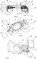
- FIG. 1 and 2 there is shown a plurality of twisting and winding devices 1 of a thread on a spindle according to the invention mounted next to one another on a bench 2 of a ring spinning machine.
- Each twisting and winding device 1 is mounted concentrically on a respective circular opening 3 obtained in the bench 2.
- each circular opening 3 a spindle is positioned which is rotated by a head motor of the spinning machine together with all the other spindles of the same front of the spinning machine.
- the rotation of the spindle tautens the thread, one end of which is fixed to the spindle, which rotates some components of the twisting and winding device 1.
- the bench 2 is driven to move opportunely in a vertical direction, i.e. along a direction that is substantially parallel to an axis X ( Figure 3 ) of each circular opening 3.
- the thread which has been previously stretched by a plurality of pairs of rollers rotating at different speeds, is twisted and wound around the spindle so as to make a spool of a set type of yarn.
- the bench 2 is made of extruded aluminium that enables the weight thereof to be limited with respect to the benches of traditional spinning machines made by folding a steel sheet to compensate for the greater weight of the twisting and winding devices 1 according to the invention with respect to the twisting and winding devices of known type, due to the presence of an electromagnet with relative control electronics, for each device, as will be explained below.
- Each circular opening 3 can have a diameter of about 75 mm and the distance between the axes X of two adjacent circular openings 3 can be about 82,5 mm. Such dimensions enable the assembly and maintenance operations to be facilitated that are to be performed on the twisting and winding devices 1.
- Each twisting and winding device 1 comprises an electronic control unit 4, which is visible in Figure 2 and shown in particular in Figure 4 , and a twisting and winding unit 5 visible in Figure 1 .
- the twisting and winding unit 5 comprises rotating components that engage the thread and are rotated by the tension of the thread that is tautened between the components and the rotated spindle. In this manner, these rotating components enable the thread to be twisted and wound around the spindle.
- the electronic control unit 4 is arranged, in particular, for exerting a controlled braking action on the rotating components of the twisting and winding unit 5 according to the advancement of a spinning cycle of the thread.
- the speed of the rotating components may have to be varied according to the cycle stage or, for example, when it is necessary to stop and then restart a spindle because of the breakage of the thread.
- the bench 2 has a substantially C-shaped section and comprises a plurality of cooling fins 6 protruding from an outer side wall 7 of the bench 2 to the outer environment so as to thus increase the radiant surface to promote dissipation of heat through convection.
- cooling fins 6 are arranged parallel to one another and substantially travel the entire length of the bench 2.
- the cooling fins 6 act as heat sinks, in particular of the heat generated by the twisting and winding unit 5, thus enabling the ambient temperature to be lowered and preventing the twisting and winding unit 5 and/or the electronic control unit 4 from overheating, causing wear thereto and/or a malfunction thereof.
- each electronic unit 4 comprises a braking device, in particular an electromagnet 9, and an electronic card 10 arranged for controlling a braking action that the electromagnet 9 exerts on a rotating component of the twisting and winding unit 5.
- Each electronic unit 4 comprises a body 8 that is preferably made of plastics, in which a housing 19 is made for the electromagnet 9 and a further housing 20 for the electronic card 10, which are shown schematically in Figures 5 and 6 .
- the body 8 is approximately parallelpipedon-shaped and can have profiles with grooved zones 11 arranged for decreasing the volume of the electronic control unit 4 and, consequently, the corresponding mass, to be less of a burden on the support elements of the spinning machine that have to support the bench 2.
- a through hole 12 is further obtained that, in use, like the circular opening 3, surrounds the spindle.
- housing connecting means 14 of known type, comprising for example screws and shown from above in Figure 1 , which interacts with respective connecting holes made in the bench 2 and enables the electronic control unit 4 to be fixed in a preset position on the bench 2.
- the through hole 12 and the circular opening 3 are concentric when the electronic unit 4 is mounted on the bench 2.
- the electronic control unit 4 further comprises a light source 15 arranged for sending an optical signal to an operator, or to an optical supervision system, to indicate an operating condition of the twisting and winding unit 5.
- the light source 15 can comprise a first light source 16 and a second light source 17 each of which is arranged for emitting a light of a different colour from one another, for example green and red, respectively.
- a different meaning known to the operator can be assigned to this colour, depending on the condition that it is desired to indicate.
- the light emission of the first light source 16 can be assigned a condition of good operation of the twisting and winding unit 5, i.e. a condition in which the thread is kept taut and is not therefore interrupted, and in which the rotating components of the twisting and winding unit 5 rotate correctly.
- the light emission of the second light source 17 can be assigned a condition of malfunction of the twisting and winding unit 5, which is either due to the fact that the rotating components of the twisting and winding unit 5 do not rotate correctly, which indicates a problem with the twisting and winding unit 5, or is due to the fact that the twisting and winding unit 5 is stationary, which indicates an interruption to the thread, which, no longer being taut, does not rotate the rotating components of the twisting and winding unit 5 around the spindle.
- the conditions of good operation or malfunction of the twisting and winding unit 5 are established on the basis of the actual rotation speed of the rotating components of the twisting and winding unit 5 detected by a speed sensor 18 provided in the electronic control unit 4.
- the speed sensor 18 is arranged in a still further housing 21 obtained in the body 8 shaped in such a manner that the speed sensor 18 faces the through hole 12, once it has been mounted in the still further housing 21. In this manner, the speed sensor 18, in use, is able to detect a rotation speed of the rotating components of the twisting and winding unit 5.
- the speed sensor 18 can be, for example, of the optical Hall-effect type.
- the speed sensor 18 is optical, it comprises a reflective strip arranged on about 50% of the circumference of the through hole 12, so as to detect with precision also the higher speeds (30-40.000 rpm) of the rotating components of the twisting and winding unit 5.
- the value of the rotation speed of the twisting and winding unit 5 is then transmitted by the speed sensor 18 to the electronic card 10, which compares the value of the detected speed with that of the set reference value.
- the set reference value is variable during the spinning cycle, for example depending on the stage of creation of the spool.
- the first and the second light source 16, 17 can be supplied alternately by the electronic card 10, in particular by a switch driven by a relay supplied by the electronic card 10.
- the electronic card 10 commands the relay to supply the second light source 17, whereas when the rotation speed of the rotating components of the twisting and winding unit 5 remains within a range of values around the set reference value, the electronic card 10 commands the relay to keep the first light source 16 supplied.
- a rotation speed below the set reference value of the rotation speed is a sign of a malfunction of the twisting and winding unit 5, inasmuch as the rotating components of the latter rotate, but at reduced speed, whereas a rotation speed in particular equal to 0 is a sign of a breakage of the thread inasmuch as the twisting and winding unit 5 no longer rotates.
- the first light source 16 and the second light source 17 can each comprise a LED to generate the respective light emission.
- the light source 15 can also comprise a single LED, which, for example, is assigned a good operation condition of the twisting and winding unit 5 when it does not generate a light emission, or which is assigned a malfunction condition when it is supplied, i.e. when it generates a light emission.
- the operator Owing to the light source 15, the operator is able to establish whether a thread which a given twisting and winding device 1 was twisting and winding is broken or not by merely checking visually the light signal. In this manner it is avoided that the operator has to proceed along the entire length of each front of the spinning machine, trying to make contact with the thread to check whether the thread broke during the spinning cycle. Consequently, the maintenance operations of the twisting and winding devices 1 of a thread on a spindle are more rapid than the twisting and winding devices of known type and it is possible for the operator to intervene promptly and directly on the broken thread or on the malfunctioning twisting and winding unit 5.
- the light source 15 has to protrude from an upper face 22 of the electronic unit 4 and a suitable passage 23 has to be obtained in the bench 2 to be able to permit that, when the electronic control unit 4 is mounted on the bench 2, the light source 15 protrudes to the outer environment.
- the electronic card 10 is supplied through a power supply line 24 carrying live voltage into which the electronic card 10 is plugged by electric connecting plugs 25 when the electronic control unit 4 is mounted on the bench 2.
- the electric connecting plugs 25 have a length that is such as to enable contact with the supply line 24 during assembly. In this manner, the electronic card 10 is easily connected to the electric supply without any additional wiring having to be provided. This permits very rapid maintenance and assembly.
- the supply line 24 is arranged in a longitudinal seat 26 obtained along the entire length of the bench 2.
- the electronic card 10 in addition to controlling the supply of the light source 15, communicates through a data communication channel, not shown, for example a data transmission bus, with a central control unit of the spinning machine.
- the central control unit comprises software arranged for managing the spinning cycle and rotating the motors of the spindles.
- the central control unit further, sends data to the electronic card 10, on the basis of which the latter controls the twisting and winding unit 5.
- the central control unit informs the electronic card 10 of the specific operating parameters for each stage of a spinning cycle.
- the electronic card 10 sends the central control unit status signals and alarms, for example indicating a malfunction of the twisting and winding unit 5.
- a supply line 24 is shown in the form of an electrified track.
- the supply line 24 comprises a pair of supply cables, in particular that supply a direct current.
- the data transmission bus uses the same cables as the supply line 24.
- the supply line 24 can provide several cables, and, correspondingly, the electronic card 10 will comprise a number of electric connecting plugs 25 equal to the number of cables of the supply line 24, the signal transmission cable being, in this case, independent of the supply line 24.
- the electronic card 10 comprises electronic components 27 of known type, schematically illustrated in Figures 5 and 6 , suitable for establishing the communication with the central control unit of the spinning machine and with the light source 15.
- the further housing 20 obtained in the body 8 for housing the electronic card 10 has an upwardly open substantially box shape.
- the electronic card 10 is located during the assembly step inside the further housing 20.
- the further housing 20 can be made integrally on the body 8 and can be provided at a first end of the body 8.
- a cover 28 is provided for engaging with a perimeter 29 of the further housing 20 such as to close the latter and protect the electronic components 27 from foreign bodies, for example from dust.
- the electromagnet 9 is connected electrically to the supply line 24 with a fixed connector, which is not shown, that engages automatically during the assembly step. In this manner, maintenance and assembly are facilitated and rapid.
- suitable electric tracks are provided that are not illustrated that are arranged for taking the electric supply to the electromagnet 9.
- the electromagnet 9 is further arranged on an opposite side of the through hole 12 with respect to the electronic card 10 and is separated from the latter.
- the electromagnet 9 can comprise a plurality of packed insulated laminations and a winding with a great number of coils in order to have minimum absorption.
- the housing 19 of the electromagnet 9 is arranged in the body 8 in such a manner that the electromagnet 9, once it is mounted, embraces at least partially the through hole 12 and thus, in use, the twisting and winding unit 5, in order to interact with a rotating component of the twisting and winding unit 5 to vary the rotation speed thereof, in particular to exert a braking action on the aforesaid rotating component.
- the electromagnet 9 generates a magnetic field due to the passage of the current through the winding thereof.
- the magnetic field is in turn variable and thus also the intensity of the braking force produced.
- the electronic card 10 constantly receives the value of the actual rotation speed of the rotating components of the twisting and winding unit 5 detected by the speed sensor 18, the reference value for the rotation speed of the rotating components of the twisting and winding unit 5 so as to obtain correct twisting and tensioning of the thread around the spool, this reference value being sent by the central control unit to the electronic card 10, and, lastly, an operating parameter indicating the cyclical vertical movement of the bench 2 in such a manner that the electronic card 10 can make the necessary corrections according to the actual winding diameter of the thread on the spindle, also this parameter being sent by the central control unit to the electronic card 10.
- the electronic card 10 compares the detected speed with the set speed. When the detected speed is greater than the set speed, it commands an increase in the intensity of the electric current of the electromagnet 9 so as to increase the intensity of the magnetic field generated and, consequently, the braking action thereof, vice versa, if the detected speed is less than the set speed, it commands a reduction in the intensity of the current of the electromagnet 9, so as to decrease the intensity of the magnetic field generated and, consequently, the braking action thereof.
- the speed value that is detected constantly by the speed sensor 18 is used to decide if it is necessary to exert and to what extent braking of the sleeve 40 by comparing the detected speed value with a reference value that is stored in the electronic card 10 and is variable during the spinning cycle.
- the electronic card 10 owing to the modulation of the current that passes through the winding of the electromagnet 9, is able to perform a start-up procedure until the working speed of a twisting and winding unit 5 is reached, for example, after breaking of the thread and the subsequent repair performed by an operator on the basis of the operating parameters sent by the central control unit.
- the electronic card 10 is thus able to optimise braking during the entire spinning cycle, according to the speed variations of the thread provided according to the steps of the spinning cycle.
- the twisting and winding unit 5 comprises an inner ring 30 and an outer ring 31 between which an annular positioning element 32 supporting in preset positions a plurality of revolving bodies 33 is interposed.
- the revolving bodies 33 can be three in number, as in the Figures, arranged substantially at 120° from one another, but the number can be varied.
- the revolving bodies 33 are made of ceramic material so as to be able to reach and maintain high rotation speeds.
- the revolving bodies 33 are made of silicon nitride.
- the annular positioning element 32 is provided with a plurality of substantially C-shaped downward-facing projections 34, each of which forms a positioning seat 35 for a respective revolving body 33, this positioning seat 35 being arranged for embracing partially a respective revolving body 33 and maintaining the revolving body 33 in the aforesaid preset position.
- the plurality of projections 34 is shaped in such a manner that, in use, each revolving body 33 is inserted inside a respective positioning seat 35 with clearance in such a manner as to be free to rotate in the interior thereof. Accordingly, for this purpose, the positioning seat 35 has to be suitably dimensioned according to the dimensions of the revolving bodies 33.
- Each revolving body 33 can have a substantially spherical shape.
- the outer ring 31 is mounted on an edge of the circular opening 3 of the bench 2 and is the only component of the twisting and winding unit 5 that does not rotate around the spindle.
- the outer ring 31 is moreover arranged resting on a resting seat 51 provided in the body 8 of the electronic control unit 4, shown for example in Figure 6 .
- the resting seat 51 is positioned and shaped in such a manner that when the outer ring 31 rests thereupon the connecting means 14 can interact with a portion of an upper surface 53 of the outer ring 31 to immobilise the outer ring 31 on the bench 2 together with the electronic control unit 4.
- the outer ring 31 and the inner ring 30 can be made of a ceramic material, or of steel.
- the outer ring 31 and the inner ring 30 have a substantially C-shaped section, such sections facing one another in an assembly step.
- an inner surface 36 of the outer ring 31 has a first groove 37
- an outer surface 38 of the inner ring 30 has a second groove 39 that in use, facing one another, make up a rolling track for the revolving bodies 33.
- the rolling track of the revolving bodies 33 can have an oblique contact that enables also axial loads to be supported in addition to radial loads. In this manner, the twisting and winding unit 5 is able to contrast traction upwards due to the fact that the traction of the thread is greater than the mass of the rotating revolving bodies 33.
- the twisting and winding unit 5 further comprises a sleeve 40 made of a highly conductive metal material that is suitable for interacting with the electromagnet 9, and is obtained, for example, by turning an extruded bar.
- the inner hole of the sleeve 40 can have a diameter of 55 mm. Aluminium is preferably used as a highly conductive metal material because of the low specific weight thereof.
- the inner ring 30 is mounted, in use, against a portion of an outer wall 41 of the sleeve 40.
- the inner ring 30 can be fixed to the outer wall 41 by a structural adhesive so as to avoid mechanical stress to the inner ring 30.
- the annular positioning element 32 can be made of a technopolymer that is suitable for high temperatures, is hard-wearing and has a very low friction coefficient. Such a technopolymer gives the annular positioning element 32 a high degree of elasticity that enables the revolving bodies 33 to be mounted correctly without requiring the ceramic or steel internal and external rings 30, 31 to be deformed.
- an upper edge 52 of the inner ring 30 is received with interference fit in a connecting seat of the annular positioning element 32, which is not illustrated in the
- the inner ring 30, with the sleeve 40 fixed thereto, and the outer ring 31 are mounted concentrically to the circular opening 3 and thus substantially coaxially with the spindle provided inside the circular opening 3.
- the diameters of the inner ring 30 and of the sleeve 40 have to be less than the diameter of the outer ring 31.
- the connecting means 14 is inserted in such a manner as to engage the electronic control unit 4, the twisting and winding unit 5 and the bench 2 reciprocally through the interaction with the through openings 13 of the electronic control unit 4, with the portion of the upper surface 53 of the twisting and winding unit 5 and with the connecting holes of the bench 2.
- a hole 42 is obtained arranged for housing and engaging a guiding element 43 for guiding the thread.
- the guiding element 43 is substantially C-shaped, in such a manner that one end of the C can be inserted inside the hole 42.
- the guiding element 43 for guiding the thread is arranged in order that the stretched thread to be subjected to twisting and winding is inserted therein and engages a portion of an inner area 44 of the guiding element 43.
- the bench is driven appropriately in a vertical direction, i.e. along a direction that is substantially parallel to the axis of each spindle.
- the rotating components of the twisting and winding unit 5 are the inner ring 30, the annular positioning element 32, the revolving bodies 33 and the sleeve 40.
- the outer ring 31 is on the other hand fixed.
- the guiding element 43 for guiding the thread can comprise a protruding element, not shown in the Figures, made of a ceramic material and arranged for reducing wear and increasing the range of curvature of the thread in transit. This protruding element is fixed in an upper portion of the C of the guiding element 43 for guiding the thread.
- the twisting and winding device 1 comprises a pressurised air delivery system 45 obtained in the body 8, shown in particular in Figure 3 .
- the pressurised air delivery system 45 communicates on one side with a conduit 46 obtained in the thickness of the bench 2 through an air supply hole 47 ( Figure 6 ), and on the other side leads into an upper zone of the body 8 located near the circular opening 3 through an air outlet hole 48.
- the air outlet hole 48 is in flowing communication with the rolling track when the twisting and winding unit 5 and the electronic control unit 4 are mounted on the bench 2.
- the compressed air generated for example by an external pump, is supplied to the pressurised air delivery system 45 through the conduit 46.
- the pressurised air delivery system 45 can comprise one or more air delivery channels obtained in the body 8.
- a seal 49 is arranged, for example an O-ring, for maintaining the pressurised air delivery system 45.
- the seal 49 is housed in a respective seat 50 obtained in the body 8 of the electronic control unit 4.
- the flow of compressed air supplied to the rolling track is further used to cool the rotating components and lubricate the components occasionally, for example by means of a fluidifier in the form of powder.
- twisting and winding devices 1 have a much longer life than those of the prior art owing to the use of compressed air delivered into the rolling track of the revolving bodies 33 by the pressurised air delivery system 45. This means that maintenance costs are considerably lower than those of prior art twisting and winding devices 1.
- twisting and winding devices according to the invention are very versatile, because both the electronic control unit 4 and the twisting and winding unit 5 can also be mounted on a bench of a traditional spinning machine, i.e. be made of folded sheet metal.
- the only modification to be made to a traditional bench is to provide an electrified supply line for the electric/electronic components of the electronic control unit 4.
- both the electronic control unit 4 and the twisting and winding unit 5 are mountable in plug-and-play mode and specific electric installation procedures are not necessary owing to the absence of cabling, this significantly simplifying assembly and maintenance operations.
- an electronic card 10 is provided for each twisting and winding device 1 assigned to a respective spindle, so as to control a single braking device on the basis of the detected rotation speed of the rotating components and on the characteristic parameters of the various stages of a spinning cycle, permitting both productivity and the quality of the obtained yarn to be increased.
Landscapes
- Engineering & Computer Science (AREA)
- Mechanical Engineering (AREA)
- Textile Engineering (AREA)
- Spinning Or Twisting Of Yarns (AREA)
Claims (10)
- Dreh- und Wickelvorrichtung (1) zum Drehen und Wickeln eines Fadens auf eine Spindel, die Folgendes aufweist, nämlich eine Dreh- und Wickeleinheit (5), die angeordnet ist, um das Drehen und Wickeln des Fadens um die Spindel zu ermöglichen, und die eine Hülse (40) aufweist, die mit einem Führungselement (43) zum Führen des Fadens versehen ist, wobei die Hülse (40) so angeordnet ist, um von der Spindel durch den Faden gedreht zu werden, wobei die Dreh- und Wickelvorrichtung (1) ferner einen inneren Ring (30) aufweist, der außerhalb der Hülle (40) befestigt ist, ein ringförmiges Positionierelement (32), das zum Tragen einer Vielzahl von Drehkörpern (33) angeordnet ist, sowie einen äußeren Ring (31), der konzentrisch außerhalb des inneren Rings (30) montiert ist, wobei das ringförmige Positionierelement (32) zwischen dem inneren Ring (30) und dem äußeren Ring (31) angeordnet ist, wobei der innere Ring (30) und der äußere Ring (31) eine Rollbahn für die Vielzahl von Drehkörpern (33) bilden, wobei die Dreh- und Wickelvorrichtung (1) dadurch gekennzeichnet ist, dass sie ferner eine elektronische Steuereinheit (4) aufweist, die so angeordnet ist, dass sie eine Drehgeschwindigkeit der Hülse (40) verändert, wobei die elektronische Steuereinheit (4) einen Geschwindigkeitssensor (18) aufweist, der so angeordnet ist, dass er eine tatsächliche Drehgeschwindigkeit der Hülse (40) detektiert, sowie einen Elektromagneten (9), der so angeordnet ist, dass er mit der Hülse (40) zusammenwirkt, und eine elektronische Karte (10), die zum Variieren eines Versorgungsstroms des Elektromagneten (9) angeordnet ist, um eine Bremswirkung auf die Hülse (40) auszuüben, um die tatsächliche Drehgeschwindigkeit der Hülse (40) zu variieren, wobei die elektronische Karte (10) eingerichtet ist, um den Wert der durch den Geschwindigkeitssensor (18) erfassten tatsächlichen Drehgeschwindigkeit mit einem Referenzwert zu vergleichen und den Versorgungsstrom auf der Basis des Ergebnisses des Vergleichs zu variieren.
- Dreh- und Wickelvorrichtung (1) zum Drehen und Wickeln eines Fadens auf eine Spindel gemäß Anspruch 1, wobei die elektronische Karte (10) zum Variieren des Versorgungsstroms auf der Basis von Betriebsparametern eines Stadiums eines Spinnzyklus' des Fadens eingerichtet ist, wobei die Betriebsparameter von einer zentralen Steuereinheit, mit der die elektronische Karte über einen Datenkommunikationsbus kommuniziert, an die elektronische Karte (10) gesendet werden.
- Dreh- und Wickelvorrichtung (1) zum Drehen und Wickeln eines Fadens auf eine Spindel gemäß Anspruch 1 oder 2, wobei die elektronische Steuereinheit (4) ferner eine Lichtquelle (15) aufweist, die zum Senden eines optischen Signals an eine Bedienperson oder an ein optisches Überwachungssystem angeordnet ist, um einen Betriebszustand der Dreh- und Wickeleinheit (5) anzuzeigen.
- Dreh- und Wickelvorrichtung (1) zum Drehen und Wickeln eines Fadens auf eine Spindel gemäß Anspruch 3, wobei die Lichtquelle (15) eine erste Lichtquelle (16) und eine zweite Lichtquelle (17) aufweist, die jeweils so angeordnet sind, dass sie jeweils ein Licht emittieren, die jeweils unterschiedlich sind, wobei die erste Lichtquelle (16) und die zweite Lichtquelle (17) abwechselnd von der elektronischen Karte (10) gespeist werden.
- Dreh- und Wickelvorrichtung (1) zum Drehen und Wickeln eines Fadens auf eine Spindel nach einem der vorherigen Ansprüche, wobei die elektronische Steuereinheit (4) und die Dreh- und Wickeleinheit (5) so konfiguriert sind, dass sie im Plug-and-Play-Modus auf einer Bank (2) einer Spinnmaschine montiert werden können.
- Dreh- und Wickelvorrichtung (1) zum Drehen und Wickeln eines Fadens auf eine Spindel gemäß einem der vorherigen Ansprüche, wobei die elektronische Steuereinheit (4) ferner ein Zufuhrsystem für Druckluft (45) aufweist, das in einem Körper (8) der elektronischen Steuereinheit (4) vorgesehen ist, das zum Zuführen von Druckluft zu der Rollbahn für die Vielzahl von Drehkörpern (33) angeordnet ist.
- Bank (2) für eine Spinnmaschine, die mit zumindest einer Dreh- und Wickelvorrichtung (1) nach einem der Ansprüche 1 bis 6 versehen ist, wobei die Bank (2) aus extrudiertem Aluminium hergestellt ist und zumindest eine kreisförmige Öffnung (3) zur Aufnahme einer Spindel der Spinnmaschine, eine äußere Seitenwand (7) und eine Vielzahl von Kühlrippen (5) aufweist, die von der äußeren Seitenwand (7) zu einer äußeren Umgebung vorstehen, um so eine strahlenförmige Fläche der Bank (2) zu vergrößern.
- Bank (2) gemäß Anspruch 7, wobei der äußere Ring (31) auf der kreisförmigen Öffnung (3) montiert ist.
- Bank (2) gemäß Anspruch 8, die ferner einen Längssitz (26) aufweist, der sich über die gesamte Länge der Bank (2) erstreckt und eine Versorgungsleitung (24) aufnimmt, die zur Versorgung der elektronischen Karte (10) der Dreh- und Wickelvorrichtung (1) angeordnet ist.
- Bank (2) gemäß Anspruch 8 oder 9, die ferner eine Leitung (46) aufweist, die in einer Dicke der Bank (2) vorgesehen ist, um den Durchtritt von Druckluft zu ermöglichen, die in ein Zufuhrsystem für Druckluft (45) der Dreh- und Wickelvorrichtung (1) eingebracht wird.
Applications Claiming Priority (2)
| Application Number | Priority Date | Filing Date | Title |
|---|---|---|---|
| ITUB2015A001069A ITUB20151069A1 (it) | 2015-05-26 | 2015-05-26 | Dispositivo di torsione e avvolgimento di un filo su un fuso |
| PCT/IB2016/053069 WO2016189480A1 (en) | 2015-05-26 | 2016-05-25 | Twisting and winding device for twisting and winding a thread on a spindle |
Publications (2)
| Publication Number | Publication Date |
|---|---|
| EP3303665A1 EP3303665A1 (de) | 2018-04-11 |
| EP3303665B1 true EP3303665B1 (de) | 2020-08-12 |
Family
ID=53836757
Family Applications (1)
| Application Number | Title | Priority Date | Filing Date |
|---|---|---|---|
| EP16736616.0A Not-in-force EP3303665B1 (de) | 2015-05-26 | 2016-05-25 | Verdreh- und wickelvorrichtung zum verdrehen und aufwickeln eines fadens auf einer spindel |
Country Status (3)
| Country | Link |
|---|---|
| EP (1) | EP3303665B1 (de) |
| IT (1) | ITUB20151069A1 (de) |
| WO (1) | WO2016189480A1 (de) |
Families Citing this family (4)
| Publication number | Priority date | Publication date | Assignee | Title |
|---|---|---|---|---|
| DE102018112620A1 (de) | 2018-05-25 | 2019-11-28 | Maschinenfabrik Rieter Ag | Textilmaschine mit einer Kühlanordnung |
| IT201900019752A1 (it) | 2019-10-24 | 2021-04-24 | Cogne Macch Tessili S P A | Metodo di controllo di un filatoio per ottenere una messa a punto automatica di tale filatoio |
| CN113267499B (zh) * | 2021-06-25 | 2022-03-29 | 中国民航大学 | 一种铁丝网目数及缺陷自动检测线 |
| CN114486551B (zh) * | 2021-12-22 | 2024-05-03 | 青岛优派普环保科技股份有限公司 | 管道伴热带的连接件及管材的静液压试验机 |
Family Cites Families (7)
| Publication number | Priority date | Publication date | Assignee | Title |
|---|---|---|---|---|
| US3324643A (en) * | 1964-10-13 | 1967-06-13 | Kluttz Machine & Foundry Co | Airborne spinning or twisting ring and traveler |
| US4023342A (en) * | 1975-05-16 | 1977-05-17 | Erwin Schenkel | Ring spinning or twisting process |
| IT7983458A0 (it) * | 1979-09-24 | 1979-09-24 | Pordenone | Anello rotante. |
| IT1210038B (it) * | 1982-12-23 | 1989-09-06 | Savio Spa | Dispositivo di sostentamento e rotolamento isostatico a corpi volventi quale anello rotante. |
| JPS61152835A (ja) * | 1984-12-21 | 1986-07-11 | Kanai Hiroyuki | 回転リング |
| US4596114A (en) * | 1985-08-30 | 1986-06-24 | Ringtex Industries, Inc. | Airborne spinning or twisting ring |
| EP0326688B1 (de) * | 1988-01-30 | 1991-11-27 | Maschinenfabrik Rieter Ag | Wärmeabfuhr von Textilmaschinen |
-
2015
- 2015-05-26 IT ITUB2015A001069A patent/ITUB20151069A1/it unknown
-
2016
- 2016-05-25 WO PCT/IB2016/053069 patent/WO2016189480A1/en not_active Ceased
- 2016-05-25 EP EP16736616.0A patent/EP3303665B1/de not_active Not-in-force
Non-Patent Citations (1)
| Title |
|---|
| None * |
Also Published As
| Publication number | Publication date |
|---|---|
| EP3303665A1 (de) | 2018-04-11 |
| WO2016189480A1 (en) | 2016-12-01 |
| ITUB20151069A1 (it) | 2016-11-26 |
Similar Documents
| Publication | Publication Date | Title |
|---|---|---|
| EP3303665B1 (de) | Verdreh- und wickelvorrichtung zum verdrehen und aufwickeln eines fadens auf einer spindel | |
| CN106676690B (zh) | 一种用于操作倍捻或并捻机的锭子的方法 | |
| EP3540104A1 (de) | Strecktexturierungsmaschine | |
| KR102297263B1 (ko) | 실 헤드 로터 | |
| US20170217718A1 (en) | Method and device for operating a workstation of a yarn balloon forming textile machine | |
| CN106087142B (zh) | 倍捻机或并捻机的锭子运行方法和相应的倍捻机或并捻机 | |
| US20120001011A1 (en) | Machine for manufacturing strands from wires | |
| CN110735200B (zh) | 用于捻线机或直捻机的纱线张力影响机构 | |
| EP2966020B1 (de) | Garnspeichervorrichtung, garnwickeleinheit und garnwickelmaschine | |
| EP1734162B1 (de) | Vorrichtung zur Entfernung der Spindelwelle einer Zwirneinheit | |
| CN104627730B (zh) | 用于引导纱线的递送装置 | |
| CN1094008A (zh) | 用于纺织机上的纱线络纱方法以及实施此方法的机器 | |
| CN112916633A (zh) | 一种加热均匀的拉丝辊及应用该拉丝辊的拉丝机 | |
| CN102233466B (zh) | 剖线机 | |
| ITUA20170770A1 (it) | Banchina per un filatoio | |
| JP2009504532A (ja) | 多数本の糸を溶融紡績しかつ巻取る装置並びにこのような装置を運転する方法 | |
| US3018605A (en) | Textile lubricating apparatus | |
| KR19990066837A (ko) | 방사권취기 | |
| CN100359051C (zh) | 用于纺丝和卷绕至少一根合成丝线的装置 | |
| CN111876864A (zh) | 一种捻线机用可调式安全导线装置 | |
| KR19980032925A (ko) | 실의 가연장치 | |
| US6990795B2 (en) | Yarn false twist texturing machine | |
| KR970005099Y1 (ko) | 코일 및 요크고정식 전자클러치 | |
| US2068929A (en) | Power-transmitter | |
| CN103911710B (zh) | 一种半精纺花线机床 |
Legal Events
| Date | Code | Title | Description |
|---|---|---|---|
| STAA | Information on the status of an ep patent application or granted ep patent |
Free format text: STATUS: THE INTERNATIONAL PUBLICATION HAS BEEN MADE |
|
| PUAI | Public reference made under article 153(3) epc to a published international application that has entered the european phase |
Free format text: ORIGINAL CODE: 0009012 |
|
| STAA | Information on the status of an ep patent application or granted ep patent |
Free format text: STATUS: REQUEST FOR EXAMINATION WAS MADE |
|
| 17P | Request for examination filed |
Effective date: 20171226 |
|
| AK | Designated contracting states |
Kind code of ref document: A1 Designated state(s): AL AT BE BG CH CY CZ DE DK EE ES FI FR GB GR HR HU IE IS IT LI LT LU LV MC MK MT NL NO PL PT RO RS SE SI SK SM TR |
|
| AX | Request for extension of the european patent |
Extension state: BA ME |
|
| DAV | Request for validation of the european patent (deleted) | ||
| DAX | Request for extension of the european patent (deleted) | ||
| GRAP | Despatch of communication of intention to grant a patent |
Free format text: ORIGINAL CODE: EPIDOSNIGR1 |
|
| STAA | Information on the status of an ep patent application or granted ep patent |
Free format text: STATUS: GRANT OF PATENT IS INTENDED |
|
| INTG | Intention to grant announced |
Effective date: 20200225 |
|
| GRAS | Grant fee paid |
Free format text: ORIGINAL CODE: EPIDOSNIGR3 |
|
| GRAA | (expected) grant |
Free format text: ORIGINAL CODE: 0009210 |
|
| STAA | Information on the status of an ep patent application or granted ep patent |
Free format text: STATUS: THE PATENT HAS BEEN GRANTED |
|
| AK | Designated contracting states |
Kind code of ref document: B1 Designated state(s): AL AT BE BG CH CY CZ DE DK EE ES FI FR GB GR HR HU IE IS IT LI LT LU LV MC MK MT NL NO PL PT RO RS SE SI SK SM TR |
|
| REG | Reference to a national code |
Ref country code: CH Ref legal event code: EP |
|
| REG | Reference to a national code |
Ref country code: IE Ref legal event code: FG4D |
|
| REG | Reference to a national code |
Ref country code: DE Ref legal event code: R096 Ref document number: 602016041842 Country of ref document: DE |
|
| REG | Reference to a national code |
Ref country code: AT Ref legal event code: REF Ref document number: 1301644 Country of ref document: AT Kind code of ref document: T Effective date: 20200915 |
|
| REG | Reference to a national code |
Ref country code: LT Ref legal event code: MG4D |
|
| REG | Reference to a national code |
Ref country code: NL Ref legal event code: MP Effective date: 20200812 |
|
| PG25 | Lapsed in a contracting state [announced via postgrant information from national office to epo] |
Ref country code: LT Free format text: LAPSE BECAUSE OF FAILURE TO SUBMIT A TRANSLATION OF THE DESCRIPTION OR TO PAY THE FEE WITHIN THE PRESCRIBED TIME-LIMIT Effective date: 20200812 Ref country code: HR Free format text: LAPSE BECAUSE OF FAILURE TO SUBMIT A TRANSLATION OF THE DESCRIPTION OR TO PAY THE FEE WITHIN THE PRESCRIBED TIME-LIMIT Effective date: 20200812 Ref country code: SE Free format text: LAPSE BECAUSE OF FAILURE TO SUBMIT A TRANSLATION OF THE DESCRIPTION OR TO PAY THE FEE WITHIN THE PRESCRIBED TIME-LIMIT Effective date: 20200812 Ref country code: FI Free format text: LAPSE BECAUSE OF FAILURE TO SUBMIT A TRANSLATION OF THE DESCRIPTION OR TO PAY THE FEE WITHIN THE PRESCRIBED TIME-LIMIT Effective date: 20200812 Ref country code: NO Free format text: LAPSE BECAUSE OF FAILURE TO SUBMIT A TRANSLATION OF THE DESCRIPTION OR TO PAY THE FEE WITHIN THE PRESCRIBED TIME-LIMIT Effective date: 20201112 Ref country code: GR Free format text: LAPSE BECAUSE OF FAILURE TO SUBMIT A TRANSLATION OF THE DESCRIPTION OR TO PAY THE FEE WITHIN THE PRESCRIBED TIME-LIMIT Effective date: 20201113 Ref country code: BG Free format text: LAPSE BECAUSE OF FAILURE TO SUBMIT A TRANSLATION OF THE DESCRIPTION OR TO PAY THE FEE WITHIN THE PRESCRIBED TIME-LIMIT Effective date: 20201112 |
|
| REG | Reference to a national code |
Ref country code: AT Ref legal event code: MK05 Ref document number: 1301644 Country of ref document: AT Kind code of ref document: T Effective date: 20200812 |
|
| PG25 | Lapsed in a contracting state [announced via postgrant information from national office to epo] |
Ref country code: PL Free format text: LAPSE BECAUSE OF FAILURE TO SUBMIT A TRANSLATION OF THE DESCRIPTION OR TO PAY THE FEE WITHIN THE PRESCRIBED TIME-LIMIT Effective date: 20200812 Ref country code: RS Free format text: LAPSE BECAUSE OF FAILURE TO SUBMIT A TRANSLATION OF THE DESCRIPTION OR TO PAY THE FEE WITHIN THE PRESCRIBED TIME-LIMIT Effective date: 20200812 Ref country code: NL Free format text: LAPSE BECAUSE OF FAILURE TO SUBMIT A TRANSLATION OF THE DESCRIPTION OR TO PAY THE FEE WITHIN THE PRESCRIBED TIME-LIMIT Effective date: 20200812 Ref country code: LV Free format text: LAPSE BECAUSE OF FAILURE TO SUBMIT A TRANSLATION OF THE DESCRIPTION OR TO PAY THE FEE WITHIN THE PRESCRIBED TIME-LIMIT Effective date: 20200812 Ref country code: IS Free format text: LAPSE BECAUSE OF FAILURE TO SUBMIT A TRANSLATION OF THE DESCRIPTION OR TO PAY THE FEE WITHIN THE PRESCRIBED TIME-LIMIT Effective date: 20201212 |
|
| PG25 | Lapsed in a contracting state [announced via postgrant information from national office to epo] |
Ref country code: EE Free format text: LAPSE BECAUSE OF FAILURE TO SUBMIT A TRANSLATION OF THE DESCRIPTION OR TO PAY THE FEE WITHIN THE PRESCRIBED TIME-LIMIT Effective date: 20200812 Ref country code: SM Free format text: LAPSE BECAUSE OF FAILURE TO SUBMIT A TRANSLATION OF THE DESCRIPTION OR TO PAY THE FEE WITHIN THE PRESCRIBED TIME-LIMIT Effective date: 20200812 Ref country code: RO Free format text: LAPSE BECAUSE OF FAILURE TO SUBMIT A TRANSLATION OF THE DESCRIPTION OR TO PAY THE FEE WITHIN THE PRESCRIBED TIME-LIMIT Effective date: 20200812 Ref country code: DK Free format text: LAPSE BECAUSE OF FAILURE TO SUBMIT A TRANSLATION OF THE DESCRIPTION OR TO PAY THE FEE WITHIN THE PRESCRIBED TIME-LIMIT Effective date: 20200812 Ref country code: CZ Free format text: LAPSE BECAUSE OF FAILURE TO SUBMIT A TRANSLATION OF THE DESCRIPTION OR TO PAY THE FEE WITHIN THE PRESCRIBED TIME-LIMIT Effective date: 20200812 |
|
| REG | Reference to a national code |
Ref country code: DE Ref legal event code: R097 Ref document number: 602016041842 Country of ref document: DE |
|
| PG25 | Lapsed in a contracting state [announced via postgrant information from national office to epo] |
Ref country code: AT Free format text: LAPSE BECAUSE OF FAILURE TO SUBMIT A TRANSLATION OF THE DESCRIPTION OR TO PAY THE FEE WITHIN THE PRESCRIBED TIME-LIMIT Effective date: 20200812 Ref country code: AL Free format text: LAPSE BECAUSE OF FAILURE TO SUBMIT A TRANSLATION OF THE DESCRIPTION OR TO PAY THE FEE WITHIN THE PRESCRIBED TIME-LIMIT Effective date: 20200812 Ref country code: ES Free format text: LAPSE BECAUSE OF FAILURE TO SUBMIT A TRANSLATION OF THE DESCRIPTION OR TO PAY THE FEE WITHIN THE PRESCRIBED TIME-LIMIT Effective date: 20200812 |
|
| PLBE | No opposition filed within time limit |
Free format text: ORIGINAL CODE: 0009261 |
|
| STAA | Information on the status of an ep patent application or granted ep patent |
Free format text: STATUS: NO OPPOSITION FILED WITHIN TIME LIMIT |
|
| PG25 | Lapsed in a contracting state [announced via postgrant information from national office to epo] |
Ref country code: SK Free format text: LAPSE BECAUSE OF FAILURE TO SUBMIT A TRANSLATION OF THE DESCRIPTION OR TO PAY THE FEE WITHIN THE PRESCRIBED TIME-LIMIT Effective date: 20200812 |
|
| 26N | No opposition filed |
Effective date: 20210514 |
|
| PG25 | Lapsed in a contracting state [announced via postgrant information from national office to epo] |
Ref country code: IT Free format text: LAPSE BECAUSE OF FAILURE TO SUBMIT A TRANSLATION OF THE DESCRIPTION OR TO PAY THE FEE WITHIN THE PRESCRIBED TIME-LIMIT Effective date: 20200812 |
|
| PG25 | Lapsed in a contracting state [announced via postgrant information from national office to epo] |
Ref country code: SI Free format text: LAPSE BECAUSE OF FAILURE TO SUBMIT A TRANSLATION OF THE DESCRIPTION OR TO PAY THE FEE WITHIN THE PRESCRIBED TIME-LIMIT Effective date: 20200812 |
|
| REG | Reference to a national code |
Ref country code: DE Ref legal event code: R119 Ref document number: 602016041842 Country of ref document: DE |
|
| REG | Reference to a national code |
Ref country code: CH Ref legal event code: PL |
|
| GBPC | Gb: european patent ceased through non-payment of renewal fee |
Effective date: 20210525 |
|
| PG25 | Lapsed in a contracting state [announced via postgrant information from national office to epo] |
Ref country code: MC Free format text: LAPSE BECAUSE OF FAILURE TO SUBMIT A TRANSLATION OF THE DESCRIPTION OR TO PAY THE FEE WITHIN THE PRESCRIBED TIME-LIMIT Effective date: 20200812 Ref country code: LU Free format text: LAPSE BECAUSE OF NON-PAYMENT OF DUE FEES Effective date: 20210525 Ref country code: CH Free format text: LAPSE BECAUSE OF NON-PAYMENT OF DUE FEES Effective date: 20210531 Ref country code: LI Free format text: LAPSE BECAUSE OF NON-PAYMENT OF DUE FEES Effective date: 20210531 |
|
| REG | Reference to a national code |
Ref country code: BE Ref legal event code: MM Effective date: 20210531 |
|
| PG25 | Lapsed in a contracting state [announced via postgrant information from national office to epo] |
Ref country code: IE Free format text: LAPSE BECAUSE OF NON-PAYMENT OF DUE FEES Effective date: 20210525 Ref country code: GB Free format text: LAPSE BECAUSE OF NON-PAYMENT OF DUE FEES Effective date: 20210525 Ref country code: DE Free format text: LAPSE BECAUSE OF NON-PAYMENT OF DUE FEES Effective date: 20211201 |
|
| PG25 | Lapsed in a contracting state [announced via postgrant information from national office to epo] |
Ref country code: FR Free format text: LAPSE BECAUSE OF NON-PAYMENT OF DUE FEES Effective date: 20210531 |
|
| PG25 | Lapsed in a contracting state [announced via postgrant information from national office to epo] |
Ref country code: BE Free format text: LAPSE BECAUSE OF NON-PAYMENT OF DUE FEES Effective date: 20210531 |
|
| PG25 | Lapsed in a contracting state [announced via postgrant information from national office to epo] |
Ref country code: PT Free format text: LAPSE BECAUSE OF FAILURE TO SUBMIT A TRANSLATION OF THE DESCRIPTION OR TO PAY THE FEE WITHIN THE PRESCRIBED TIME-LIMIT Effective date: 20201214 |
|
| PG25 | Lapsed in a contracting state [announced via postgrant information from national office to epo] |
Ref country code: HU Free format text: LAPSE BECAUSE OF FAILURE TO SUBMIT A TRANSLATION OF THE DESCRIPTION OR TO PAY THE FEE WITHIN THE PRESCRIBED TIME-LIMIT; INVALID AB INITIO Effective date: 20160525 |
|
| PG25 | Lapsed in a contracting state [announced via postgrant information from national office to epo] |
Ref country code: CY Free format text: LAPSE BECAUSE OF FAILURE TO SUBMIT A TRANSLATION OF THE DESCRIPTION OR TO PAY THE FEE WITHIN THE PRESCRIBED TIME-LIMIT Effective date: 20200812 |
|
| PG25 | Lapsed in a contracting state [announced via postgrant information from national office to epo] |
Ref country code: MK Free format text: LAPSE BECAUSE OF FAILURE TO SUBMIT A TRANSLATION OF THE DESCRIPTION OR TO PAY THE FEE WITHIN THE PRESCRIBED TIME-LIMIT Effective date: 20200812 |
|
| PG25 | Lapsed in a contracting state [announced via postgrant information from national office to epo] |
Ref country code: TR Free format text: LAPSE BECAUSE OF FAILURE TO SUBMIT A TRANSLATION OF THE DESCRIPTION OR TO PAY THE FEE WITHIN THE PRESCRIBED TIME-LIMIT Effective date: 20200812 |
|
| PG25 | Lapsed in a contracting state [announced via postgrant information from national office to epo] |
Ref country code: MT Free format text: LAPSE BECAUSE OF FAILURE TO SUBMIT A TRANSLATION OF THE DESCRIPTION OR TO PAY THE FEE WITHIN THE PRESCRIBED TIME-LIMIT Effective date: 20200812 |