EP3303732B1 - Manipulateur de grande taille présentant un mât articulé rapidement repliable et déployable - Google Patents
Manipulateur de grande taille présentant un mât articulé rapidement repliable et déployable Download PDFInfo
- Publication number
- EP3303732B1 EP3303732B1 EP16731808.8A EP16731808A EP3303732B1 EP 3303732 B1 EP3303732 B1 EP 3303732B1 EP 16731808 A EP16731808 A EP 16731808A EP 3303732 B1 EP3303732 B1 EP 3303732B1
- Authority
- EP
- European Patent Office
- Prior art keywords
- boom
- mast
- speed
- articulated
- control device
- Prior art date
- Legal status (The legal status is an assumption and is not a legal conclusion. Google has not performed a legal analysis and makes no representation as to the accuracy of the status listed.)
- Active
Links
Images

Classifications
-
- B—PERFORMING OPERATIONS; TRANSPORTING
- B66—HOISTING; LIFTING; HAULING
- B66C—CRANES; LOAD-ENGAGING ELEMENTS OR DEVICES FOR CRANES, CAPSTANS, WINCHES, OR TACKLES
- B66C13/00—Other constructional features or details
- B66C13/18—Control systems or devices
- B66C13/20—Control systems or devices for non-electric drives
-
- B—PERFORMING OPERATIONS; TRANSPORTING
- B66—HOISTING; LIFTING; HAULING
- B66C—CRANES; LOAD-ENGAGING ELEMENTS OR DEVICES FOR CRANES, CAPSTANS, WINCHES, OR TACKLES
- B66C13/00—Other constructional features or details
- B66C13/18—Control systems or devices
- B66C13/46—Position indicators for suspended loads or for crane elements
-
- E—FIXED CONSTRUCTIONS
- E04—BUILDING
- E04G—SCAFFOLDING; FORMS; SHUTTERING; BUILDING IMPLEMENTS OR AIDS, OR THEIR USE; HANDLING BUILDING MATERIALS ON THE SITE; REPAIRING, BREAKING-UP OR OTHER WORK ON EXISTING BUILDINGS
- E04G21/00—Preparing, conveying, or working-up building materials or building elements in situ; Other devices or measures for constructional work
- E04G21/02—Conveying or working-up concrete or similar masses able to be heaped or cast
- E04G21/04—Devices for both conveying and distributing
-
- E—FIXED CONSTRUCTIONS
- E04—BUILDING
- E04G—SCAFFOLDING; FORMS; SHUTTERING; BUILDING IMPLEMENTS OR AIDS, OR THEIR USE; HANDLING BUILDING MATERIALS ON THE SITE; REPAIRING, BREAKING-UP OR OTHER WORK ON EXISTING BUILDINGS
- E04G21/00—Preparing, conveying, or working-up building materials or building elements in situ; Other devices or measures for constructional work
- E04G21/02—Conveying or working-up concrete or similar masses able to be heaped or cast
- E04G21/04—Devices for both conveying and distributing
- E04G21/0418—Devices for both conveying and distributing with distribution hose
- E04G21/0436—Devices for both conveying and distributing with distribution hose on a mobile support, e.g. truck
-
- E—FIXED CONSTRUCTIONS
- E04—BUILDING
- E04G—SCAFFOLDING; FORMS; SHUTTERING; BUILDING IMPLEMENTS OR AIDS, OR THEIR USE; HANDLING BUILDING MATERIALS ON THE SITE; REPAIRING, BREAKING-UP OR OTHER WORK ON EXISTING BUILDINGS
- E04G21/00—Preparing, conveying, or working-up building materials or building elements in situ; Other devices or measures for constructional work
- E04G21/02—Conveying or working-up concrete or similar masses able to be heaped or cast
- E04G21/04—Devices for both conveying and distributing
- E04G21/0418—Devices for both conveying and distributing with distribution hose
- E04G21/0445—Devices for both conveying and distributing with distribution hose with booms
-
- E—FIXED CONSTRUCTIONS
- E04—BUILDING
- E04G—SCAFFOLDING; FORMS; SHUTTERING; BUILDING IMPLEMENTS OR AIDS, OR THEIR USE; HANDLING BUILDING MATERIALS ON THE SITE; REPAIRING, BREAKING-UP OR OTHER WORK ON EXISTING BUILDINGS
- E04G21/00—Preparing, conveying, or working-up building materials or building elements in situ; Other devices or measures for constructional work
- E04G21/02—Conveying or working-up concrete or similar masses able to be heaped or cast
- E04G21/04—Devices for both conveying and distributing
- E04G21/0418—Devices for both conveying and distributing with distribution hose
- E04G21/0445—Devices for both conveying and distributing with distribution hose with booms
- E04G21/0463—Devices for both conveying and distributing with distribution hose with booms with boom control mechanisms, e.g. to automate concrete distribution
Definitions
- the invention relates to a large manipulator, in particular a truck-mounted concrete pump, with a mast trestle which can be rotated about a vertical axis by means of a rotary drive and which is arranged on a frame, an articulated mast which comprises two or more mast arms, the mast arms having articulated joints with the respective adjacent mast trestle or Mast arms are pivotally connected by means of a pivot drive, with a control device for the mast movement that controls the drives and with a mast sensor system for detecting the position of at least one point of the articulated mast or a pivot angle of at least one articulated joint, the control device being set up to determine the speed of the mast movement to the output signal of the mast sensor system.
- the invention also relates to a method for controlling the movement of an articulated mast of a large manipulator, in particular a truck-mounted concrete pump.
- Hydraulic cylinders are typically used as swivel drives, which are used to swivel the mast arms about the articulated joints relative to the adjacent mast arm or mast trestle. These are controlled by an electronic control device via proportional control valves controlled in order to be able to variably specify the travel speed of the individual hydraulic cylinders.
- the travel speed of the individual hydraulic cylinders is usually limited in known large manipulators, since moving the articulated mast too quickly poses a danger to people in the area. To ensure operational safety, there are legal standards that specify the maximum permissible speed of the tip of the articulated mast.
- control valves of the hydraulic cylinders are operated via a remote control connected to the control device (wireless or wired).
- the control valves can be controlled manually using hand levers (for example in emergency operation).
- the control valves are designed so that a specific position of an operating lever on the remote control corresponds to a defined volume flow of the hydraulic fluid, i.e. a defined travel speed of the respective hydraulic cylinder, regardless of the pressure conditions present in the hydraulic system.
- the control valves are designed in such a way that the maximum permitted speed of the mast tip is not reached when all joints are pivoted at maximum travel speed and the articulated mast is fully extended. This design of the control valves has the disadvantage that in most practical cases the legally permitted framework for the movement speed of the mast tip is very poorly utilized.
- WO 2014/166637 A1 proposes a large manipulator in which the control device provides a rapid traverse for the rotary drive of the mast trestle in order to rotate the articulated mast at increased speed into the desired working position, with the rapid traverse only being selectable when the mast or boom is completely folded.
- a single sensor connected to the The control device interacts is provided in the previously known large manipulator, with the sensor being able to determine whether the articulated mast is completely folded up or not.
- the sensor generates a release signal to the control device as long as it is ensured that the articulated mast is folded and therefore has a minimum radius. In this state, the articulated mast can be rotated at increased speed.
- the EP 3 015 625 A1 discloses a large manipulator with an articulated mast, which comprises a plurality of mast arms, the mast arms being connected to one another in a pivotally movable manner via articulated joints, with a control device controlling the mast movement and a mast sensor system detecting the position, the control device being set up to determine the speed of the mast movement based on the Limit the output signal of the mast sensor system. Also the JP 2013 091931 A reveals such a major manipulator.
- Well-known large-scale manipulators can at least determine the speed of the Limit mast movement based on the output signal of the mast sensor system, whereby a maximum movement speed for the respective articulated joint is calculated for each articulated joint individually, based on the radius of the respective articulated joint to the mast tip, which depends on the mast position, and thus the individual speeds of the drives are limited.
- the resulting speed of the tip of the articulated mast can be significantly lower than the maximum permissible mast tip speed, especially if two articulated joints are pivoted in opposite directions at the same time with the movement speed calculated for the respective articulated joint.
- the articulated mast should be able to be brought from the fully folded state into its desired working position in a minimum of time.
- the articulated mast should also be able to be transferred from the working position to the fully folded position in a minimum of time.
- the articulated mast should be able to be moved quickly from one working position to another working position when assembled.
- the invention is defined by the large manipulator according to claim 1 and by the method according to claim 9.
- the invention solves this problem starting from a large manipulator of the type mentioned in that the control device is set up to control the individual drives proportionally in accordance with a driving command, the driving command specifying the target speeds of the drives, the control device being further set up to do so to determine the speed of the tip of the articulated mast from the travel command, the lengths of the mast arms and the output signal of the mast sensor system, to reduce the speed specifications of the individual drives compared to the travel command as soon as the travel command causes the speed of the tip of the articulated mast to exceed a predetermined limit value would lead and / or exceeds the limit value, the control device being set up to reduce the speeds of all drives compared to the driving command by the same factor, so that the speed of the tip of the articulated mast is less than or equal to a predetermined limit value, regardless of the current Mast position, which results from the swivel angles of the articulated joints detected by sensors.
- the pivot angle of at least one articulated joint of the articulated mast is detected by sensors, and the speed of the mast movement is limited depending on the current pivot angle.
- the position of a point on the mast is recorded, e.g. the distance of this point to the mast trestle, and based on this, the control device limits the speed of the mast movement so that a maximum permissible speed of this point, or the speed of another point of the articulated mast derived from it , is not exceeded.
- a mast sensor system can also be provided, through which all pivot angles of the articulated joints are recorded at any time.
- the articulated mast can have an angle sensor at each articulated joint that detects the respective current pivot angle. This allows the mast speed to be optimally limited.
- the control device processes the detected swivel angles and calculates, in particular, the resulting speed of the mast tip from the positions of the mast joints and the travel speeds of the swivel drives. Based on this calculation, the drives of the articulated joints can then be controlled and the speed of at least one of the drives can be limited.
- the control device is set up to control the individual drives proportionally in accordance with a driving command, the driving command specifying the target speeds of the drives.
- the drive command results for example, from the signals from a remote control that is used by an operator of the large manipulator to control the mast movement.
- the control device controls the individual drives so that the respective travel speed corresponds to the target speed according to the travel command.
- the control device determines the speed of the tip of the articulated mast resulting from the travel command, the mast arm lengths and the current pivot angles, as explained above.
- the control device can accordingly reduce the speeds of the individual drives compared to the driving command as soon as the speed of the tip of the articulated mast exceeds a predetermined limit value, which corresponds, for example, to a legally specified maximum speed.
- the control device is preferably designed to regulate the speed of the tip of the articulated mast by controlling the drives to a value that is less than or equal to the predetermined limit value.
- the control device reduces the speeds of all drives compared to the driving command by the same factor, so that the speed of the tip of the articulated mast is always less than or equal to the predetermined limit value, regardless of the current mast position, which results from the sensor-detected pivot angles of the Articulated joints result.
- the control device is designed to derive the driving command, ie the target speeds of the individual drives, from an operating signal that specifies the target movement of the tip of the articulated mast.
- an operating signal that specifies the target movement of the tip of the articulated mast.
- the mast is located near so-called singular positions where higher speeds of the individual drives are required for precise implementation of the movement specification for the mast tip. This is the case, for example, with a fully extended mast if the user specifies a movement of the mast top in which the horizontal distance of the mast top to the mast trestle is to be reduced while maintaining the height of the mast top.
- the invention thus enables a significant improvement in the behavior of the system with Cartesian or cylindrical mast control in the vicinity of these singular positions.
- the control device determines the kinetic energy during the mast movement, taking into account the mast position and the mast speed, and limits the mast speed by controlling the mast drives so that a maximum kinetic energy of the articulated mast is not exceeded during its movement. This measure prevents mechanical overloading of the articulated mast in the event of an abrupt acceleration or deceleration of the mast movement.
- control device can include a ramp control for the speed, if necessary in conjunction with vibration damping. This allows the acceleration or braking of the articulated mast movement to be limited.
- the invention makes it possible to allow higher travel speeds at individual articulated joints of the mast, so that the legally specified framework for the mast speed can be better utilized compared to the prior art.
- the sensory detection of the mast position and the derivation of the mast kinematics from the swivel angles is the basis for regulating the travel speeds of the drives, which always ensures compliance with the legal speed limit.
- the articulated mast can be moved significantly faster than those known from the prior art Large manipulators. When unfolding and folding the articulated mast, this results in great time advantages compared to the previously known systems.
- the Figure 1 shows schematically a large manipulator according to the invention, namely a truck-mounted concrete pump, which is designated overall by the reference number 1.
- a mast frame 3 is arranged on a chassis 2 and can be rotated about a vertical axis of the truck-mounted concrete pump 1 by means of a rotary drive (not shown).
- An articulated mast designated overall by the reference number 4, is articulated to the mast trestle 3 and, in the exemplary embodiment shown, comprises four mast arms 5, 6, 7 and 8.
- the first mast arm 5 is attached to the mast frame 3 via a joint so that it can pivot about a horizontal axis.
- the pivoting movement is effected by a pivot drive (not shown for the sake of clarity).
- the remaining mast arms 6, 7 and 8 are connected to the adjacent mast arms via articulated joints so that they can pivot about parallel, horizontal axes.
- the pivoting movement is also caused by a pivot drive (not shown).
- the swivel drives each have one (or more) hydraulic cylinders that are controlled via proportional control valves. These in turn are controlled by an electronic control device (not shown) for the mast movement.
- the large manipulator 1 has a mast sensor system (eg in the form of angle sensors for the joints, displacement sensors for detecting the piston positions of the individual hydraulic cylinders or geodetic inclination sensors).
- a mast sensor system eg in the form of angle sensors for the joints, displacement sensors for detecting the piston positions of the individual hydraulic cylinders or geodetic inclination sensors.
- the control device controlling the speed of the mast movement depending on the current pivot angles ⁇ 1, ⁇ 2 , ⁇ 3 and by appropriately controlling the valves of the hydraulic cylinders ⁇ 4 of the articulated joints controls.
- the elastic deformation of the individual mast arms 5, 6, 7, 8 is neglected, so that they are viewed as rigid bodies.
- the absolute movements of the system are described in the inertial coordinate system 0 0 x 0 y 0 z 0 , ie in the coordinate system that is fixed with respect to the chassis 2.
- 0 d x d y d z d refers to the coordinate system that is rotated by the rotation angle ⁇ compared to the inertial coordinate system.
- a local coordinate system 0 i x i y i zi is defined for each mast arm 5, 6, 7, 8, the x i axis of which runs along the longitudinal axis of the respective mast arm 5, 6, 7, 8. Since the mast arms for i ⁇ 2 typically have a bend at the beginning, their longitudinal axis does not intersect the respective joint axis.
- each local coordinate system is therefore placed at the intersection of the longitudinal axis with the orthogonal straight line that runs through the joint axis.
- the kinematic relationships between the local coordinate systems and the inertial coordinate system can be represented using rotation matrices and translation vectors.
- L j denotes the length of the jth mast arm.
- the hydraulic systems used in combination with the control device enable the operator of the large manipulator according to the invention to proportionally control the travel speeds of the individual hydraulic cylinders.
- the resulting joint angular velocities can be determined based on the target speeds for the hydraulic cylinders if the translation of the joint kinematics is known.
- the control device controls the hydraulic cylinders in accordance with this modified driving command and limits their movement speed so that the mast tip EP never moves faster than legally permitted.
- the travel speed can be as fast as possible within the legal framework, which means that considerable time can be saved when unfolding and folding the articulated mast 4, but also when moving the mast between two working positions, compared to the prior art.
- sensors for detecting the positions of the end points of the mast arms relative to the mast trestle or chassis are proposed. These are generally known to those skilled in the art and can be designed, for example, as GPS, radio or ultrasonic sensors.
- Fig. 2 shown for the position of the end point EP of the last mast element 8 for example the horizontal distance ⁇ EP (the radius) of the mast tip to the inertial coordinate system is recorded by measurement.
- the horizontal path speed should only be set to one value, regardless of the movement specifications for the individual cylinders ⁇ Max E.P are limited, the particularly simple requirement for compliance with the inequality arises ⁇ ⁇ d ⁇ ⁇ Max E.P ⁇ E.P .
- a ramp control and a system for active vibration damping are proposed.
- the dynamic load can be reduced through active vibration damping, as any vibrations that occur can be quickly corrected.
- the first deflection of a vibration caused by an abrupt change in movement specified by the user remains largely intact even despite vibration damping, but can be effectively reduced, for example, by ramp control.
- This can e.g. B. as Actuating rate limitation can be implemented, in which the amount of the rate of change of the speed setpoints is limited to a maximum value.
- the adjustment rate limitation can be in the form ⁇ ⁇ i d kT a ⁇ ⁇ ⁇ i d ( k ⁇ 1 T a T a ⁇ R Max , describe with a maximum permitted adjustment rate R max .
- a further embodiment of a ramp control is a time-delayed first-order holding element.
- This procedure has the advantage that the user has a uniform deceleration behavior of the system for the entire adjustment range.
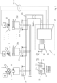
- FIG. 3 shows a block diagram with an embodiment of the mast sensor system for controlling the mast arm 4 of a large manipulator 1 according to the invention, in which the speed of the mast movement is controlled or limited depending on the current mast position.
- the articulated mast 4 is controlled by a remote control 10 by an operator using the two joysticks 11a and 11b.
- the joystick 11a for example, the rotational movement of the rotary drive of the articulated mast 4 is controlled and with the joystick 11b, for example, the pivot drives of the individual articulated joints of the articulated mast 4 are controlled.
- Position B corresponds to the simple control of the mast arm 4 as in the prior art.
- the mast speed is optimized or maximized according to the invention.
- the control signals of the joysticks 11a, 11b and the switching position of the rotary switch 12 are transmitted to the mast control 15 with processor 17 via a radio interface 13/14.
- the processor 17 receives the output signals of the mast sensor system via the signal lines 26a-d, which correspond to the pivot angles ⁇ 1 to ⁇ 4 of the individual articulated joints of the articulated mast 4 or can be derived from them.
- the angles can, for example, be recorded directly using rotation angle sensors, which also work without contact (e.g. according to the Hall principle).
- the articulation angles of the articulating mast 4 can also be determined in the processor 17 based on signals from geodetic inclination sensors which are attached to the individual mast arms 5-8.
- the processor 17 will not take the pivot angles ⁇ 1 to ⁇ 4 into account when controlling the articulated mast 4 and will control the hydraulic valves 20 and 21a-c in such a way that the predeterminable movement speeds of the individual drives are set to fixed Values are limited, which ensure compliance with legal standards regardless of the current swivel angles, ie the articulated mast behaves when controlled as is known in the prior art.
- the control signals from the processor 17 are sent via the control lines 24a - 24d and 25 to the proportional hydraulic valves 20 and 21a to 21d, the hydraulic valve 20 controlling, for example, a hydraulic motor 22, which sets the mast frame 3 in a rotary movement and the hydraulic valves 21a - 21d control the hydraulic cylinders 23a-d, which cause the mast arms 5 - 8 of the articulated mast 4 to pivot, if necessary with the help of suitable deflection levers.
- the processor 17 determines the mast position of the articulated mast 4 based on the determined articulation angles ⁇ 1 to ⁇ 4. It controls then the movement of the articulated mast 4 via the hydraulic valves 20, 21a-21d so that the path speed of the articulated mast 4 at the end point EP does not exceed a predetermined speed of the end point EP.
- the processor 17 also determines the kinetic energy of the mast 4 from the mast position and the calculated mast speed and, as explained above, takes this into account when controlling the hydraulic valves 20, 21a-21d. As a result, a maximum permitted kinetic energy of the moving articulated mast 4 is not exceeded.
- the processor 17 can use an algorithm for vibration damping, which reduces vibrations of the articulated mast 4, for example when braking or during concreting work. This makes it possible to reduce the load on the articulated mast 4, particularly when braking the mast, as already explained above. Furthermore, the processor 17 can provide a ramp control when controlling the articulated mast 4 when accelerating and decelerating the movement of the articulated mast 4, as described in detail above. The ramp control further reduces the load on the articulated mast 4.
Landscapes
- Engineering & Computer Science (AREA)
- Architecture (AREA)
- Mechanical Engineering (AREA)
- Civil Engineering (AREA)
- Structural Engineering (AREA)
- Automation & Control Theory (AREA)
- Manipulator (AREA)
Claims (11)
- Manipulateur de grande taille (1), en particulier pompe à béton automotrice, comportant un support de mât (3), qui peut tourner sur un axe vertical au moyen d'un entraînement en rotation et qui est disposé sur un châssis (2), un mât articulé (4), qui comprend deux bras de mât (5, 6, 7, 8) ou plus, les bras de mât (5, 6, 7, 8) étant reliés, par le biais d'articulations, au support de mât (3) ou au bras de mât (5, 6, 7, 8) respectivement voisin de manière mobile en pivotement au moyen respectivement d'un entraînement en pivotement, un dispositif de commande (17) commandant les entraînements pour le mouvement du mât, et un ensemble de capteurs pour le mât servant à détecter la position d'au moins un point du mât articulé (4) ou un angle de pivotement (ϕ 1 , ϕ 2 , ϕ 3 , ϕ 4) d'au moins une articulation, le dispositif de commande (17) étant configuré pour limiter la vitesse du mouvement de mât en fonction du signal de sortie de l'ensemble de capteurs pour le mât,
dans lequel
le dispositif de commande (17) est configuré pour commander les différents entraînements proportionnellement selon une instruction de marche, l'instruction de marche prédéfinissant les vitesses théoriques des entraînements, le dispositif de commande (17) étant en outre configuré pour déterminer la vitesse de la pointe (EP) du mât articulé (4) résultant de l'instruction de marche, des longueurs des bras de mât (5, 6, 7, 8) et du signal de sortie de l'ensemble de capteurs pour le mât, réduire les consignes de vitesse des différents entraînements par rapport à l'instruction de marche dès que l'instruction de marche entraînerait un passage de la vitesse de la pointe (EP) du mât articulé (4) au-dessus d'une valeur limite prédéfinie et/ou dépasse la valeur limite, le dispositif de commande (17) étant configuré pour réduire du même facteur les vitesses de tous les entraînements par rapport à l'instruction de marche, de telle sorte que la vitesse de la pointe (EP) du mât articulé (4) est inférieure ou égale à une valeur limite prédéfinie, et ce indépendamment de la position de mât actuelle qui résulte des angles de pivotement (ϕ 1 , ϕ 2 , ϕ 3 , ϕ 4) des articulations détectés par des capteurs. - Manipulateur de grande taille (1) selon la revendication 1, caractérisé en ce que le dispositif de commande (17) est configuré pour limiter la vitesse d'au moins un des entraînements.
- Manipulateur de grande taille (1) selon l'une des revendications précédentes, caractérisé en ce que le dispositif de commande (17) est configuré pour limiter la vitesse d'un point du mât articulé (4).
- Manipulateur de grande taille (1) selon l'une des revendications 1 à 3, caractérisé en ce que l'ensemble de capteurs pour le mât détecte la position relative de l'au moins un point du mât articulé (4) par rapport au support de mât (3).
- Manipulateur de grande taille (1) selon l'une des revendications 1 à 4, caractérisé en ce que le dispositif de commande (17) est configuré pour réguler, par la commande des entraînements, la vitesse de la pointe (EP) du mât articulé à une valeur qui est inférieure ou égale à une valeur limite prédéfinie.
- Manipulateur de grande taille (1) selon l'une des revendications 1 à 5, caractérisé en ce que le dispositif de commande (17) est configuré pour dériver une instruction de marche d'un signal de commande qui prédéfinit le mouvement théorique de la pointe (EP) du mât articulé (4).
- Manipulateur de grande taille (1) selon l'une des revendications 1 à 6, caractérisé en ce que le dispositif de commande (17) est configuré pour déterminer l'énergie cinétique du mât articulé (4) et limiter la vitesse du mât de telle manière qu'une énergie cinétique maximale du mât articulé (4) n'est pas dépassée lors du mouvement de celui-ci.
- Manipulateur de grande taille (1) selon l'une des revendications 1 à 7, caractérisé en ce que le dispositif de commande (17) comprend une commande de rampe.
- Procédé de commande du mouvement d'un mât articulé (4) d'un manipulateur de grande taille (1), en particulier une pompe à béton automotrice, l'angle de pivotement (ϕ 1, ϕ 2 , ϕ 3 , ϕ 4) d'au moins une articulation du mât articulé (4) ou la position d'au moins un point du mât articulé (4) étant détectés par des capteurs et la vitesse du mât articulé (4) étant limitée en fonction des signaux détectés par des capteurs,
dans lequel
les différents entraînements des articulations sont commandés proportionnellement selon une instruction de marche, l'instruction de marche prédéfinissant les vitesses théoriques des entraînements et la vitesse de la pointe (EP) du mât articulé (4) étant déterminée à partir de l'instruction de marche, des longueurs de bras de mât (5, 6, 7, 8) du mât articulé (4) et des angles de pivotement (ϕ 1, ϕ 2 , ϕ 3 , ϕ 4) actuels et/ou de la position d'au moins un point du mât articulé (4), les consignes de vitesse des différents entraînements étant réduites par rapport à l'instruction de marche, de telle sorte que la vitesse de la pointe (EP) du mât articulé (4) ne dépasse jamais une valeur limite prédéfinie, les vitesses de tous les entraînements étant réduites du même facteur par rapport à l'instruction de marche, de telle sorte que la vitesse de la pointe (EP) du mât articulé (4) est inférieure ou égale à une valeur limite prédéfinie, et ce indépendamment de la position de mât actuelle qui résulte des angles de pivotement (ϕ 1, ϕ 2 , ϕ 3 , ϕ 4) des articulations détectés par des capteurs. - Procédé selon la revendication 9, caractérisé en ce que la vitesse de la pointe (EP) du mât articulé (4) est régulée, par la commande des entraînements, à une valeur qui est inférieure ou égale à une valeur limite prédéfinie.
- Procédé selon la revendication 9 ou 10, caractérisé en ce que l'instruction de marche est dérivée d'un signal de commande qui prédéfinit le mouvement théorique de la pointe (EP) du mât articulé (4).
Applications Claiming Priority (2)
| Application Number | Priority Date | Filing Date | Title |
|---|---|---|---|
| DE102015108473.2A DE102015108473A1 (de) | 2015-05-28 | 2015-05-28 | Großmanipulator mit schnell ein- und ausfaltbarem Knickmast |
| PCT/EP2016/062183 WO2016189169A1 (fr) | 2015-05-28 | 2016-05-30 | Manipulateur de grande taille présentant un mât articulé rapidement repliable et déployable |
Publications (2)
| Publication Number | Publication Date |
|---|---|
| EP3303732A1 EP3303732A1 (fr) | 2018-04-11 |
| EP3303732B1 true EP3303732B1 (fr) | 2024-03-06 |
Family
ID=56203311
Family Applications (1)
| Application Number | Title | Priority Date | Filing Date |
|---|---|---|---|
| EP16731808.8A Active EP3303732B1 (fr) | 2015-05-28 | 2016-05-30 | Manipulateur de grande taille présentant un mât articulé rapidement repliable et déployable |
Country Status (5)
| Country | Link |
|---|---|
| US (1) | US10625990B2 (fr) |
| EP (1) | EP3303732B1 (fr) |
| CN (1) | CN107849856B (fr) |
| DE (1) | DE102015108473A1 (fr) |
| WO (1) | WO2016189169A1 (fr) |
Families Citing this family (18)
| Publication number | Priority date | Publication date | Assignee | Title |
|---|---|---|---|---|
| AT514116A1 (de) * | 2013-04-09 | 2014-10-15 | Ttcontrol Gmbh | Regelsystem und Verfahren zum Steuern der Orientierung eines Segments eines Manipulators |
| CN108349714B (zh) * | 2015-10-16 | 2019-09-03 | 帕尔芬杰尔股份有限公司 | 包括控制装置和移动式控制模块的组件 |
| DE102016125145A1 (de) * | 2016-12-21 | 2018-06-21 | Schwing Gmbh | Großmanipulator mit automatisiertem Mastaufbau |
| DE102017107430B4 (de) * | 2017-04-06 | 2024-10-17 | Schwing Gmbh | Drehwinkelsensorhaltesystem |
| DE102017208031A1 (de) * | 2017-05-12 | 2018-11-15 | Putzmeister Engineering Gmbh | Gekröpfter Auslegerarm mit veränderlichem Querschnitt für mobile Betonpumpen |
| US10315850B2 (en) | 2017-07-13 | 2019-06-11 | 1875452 Alberta Ltd. | Proppant conveyor systems and methods of use |
| IT201800006838A1 (it) * | 2018-07-02 | 2020-01-02 | Macchina operatrice mobile e metodo di funzionamento di tale macchina operatrice mobile | |
| CN109057350A (zh) * | 2018-09-30 | 2018-12-21 | 中铁六局集团广州工程有限公司 | 混凝土浇筑装置及浇筑系统 |
| US11162232B2 (en) | 2018-10-08 | 2021-11-02 | Ligchine International Corporation | Drive system for screeding concrete |
| CN109571481A (zh) * | 2018-12-30 | 2019-04-05 | 深圳市越疆科技有限公司 | 一种关节奇异点处理方法、装置、设备和存储介质 |
| CN110374333B (zh) * | 2019-06-25 | 2020-08-14 | 中联重科股份有限公司 | 泵车臂架控制方法、泵车臂架控制系统及泵车 |
| DE102019129810A1 (de) | 2019-11-05 | 2021-05-06 | Putzmeister Engineering Gmbh | Verfahren, Steuereinrichtung, System, Betonverteilermast und Computerprogramm zum Steuern der Bewegung eines Endschlauchs |
| US12151601B2 (en) * | 2020-03-31 | 2024-11-26 | Triple C Manufacturing, Inc. | Proportional control of vehicle-mounted lifting arms using electronic servomechanism-operated hydraulic valves |
| WO2022182755A1 (fr) | 2021-02-23 | 2022-09-01 | Ligchine International Corporation | Appareil de lissage de béton à flèche pivotante |
| WO2022221311A1 (fr) | 2021-04-12 | 2022-10-20 | Structural Services, Inc. | Systèmes et procédés pour aider un opérateur de grue |
| US12195306B2 (en) | 2021-04-12 | 2025-01-14 | Structural Services, Inc. | Systems and methods for identifying and locating building material objects |
| US20230151624A1 (en) | 2021-11-12 | 2023-05-18 | EZ Placer, LLC | Mobile concrete distribution system |
| CN119223661B (zh) * | 2024-12-03 | 2025-02-25 | 枣庄矿业(集团)付村煤业有限公司 | 一种单轨吊坡道轨道运行惯性超载距离测量装置 |
Citations (1)
| Publication number | Priority date | Publication date | Assignee | Title |
|---|---|---|---|---|
| EP2386387B1 (fr) * | 2009-07-06 | 2013-03-27 | Hunan Sany Intelligent Control Equipment Co., Ltd | Dispositif de commande de support de bras pour engin de travaux publics, système de commande, engin de travaux publics et procédé de commande |
Family Cites Families (57)
| Publication number | Priority date | Publication date | Assignee | Title |
|---|---|---|---|---|
| DE69025471T2 (de) * | 1990-03-23 | 1996-08-22 | Kobe Steel Ltd | Verfahren und vorrichtung zur steuerung des abbremsens der drehbewegung des oberen drehteils von baumaschinen und rechengerät zur ermittlung des neigungswinkels |
| US6025686A (en) * | 1997-07-23 | 2000-02-15 | Harnischfeger Corporation | Method and system for controlling movement of a digging dipper |
| US6202013B1 (en) * | 1998-01-15 | 2001-03-13 | Schwing America, Inc. | Articulated boom monitoring system |
| JP2000034093A (ja) * | 1998-07-21 | 2000-02-02 | Kobe Steel Ltd | 旋回式作業機械とその安全作業領域及び定格荷重の設定方法 |
| US6808025B2 (en) * | 1999-09-10 | 2004-10-26 | Schwing America, Inc. | Fire-fighting system having improved flow |
| US6351696B1 (en) * | 1999-09-10 | 2002-02-26 | Schwing America, Inc. | Automatic leveling system for articulated boom |
| DE10046546A1 (de) * | 2000-09-19 | 2002-03-28 | Putzmeister Ag | Großmanipulator mit Schwingungsdämpfer |
| EP1340858B1 (fr) * | 2000-11-17 | 2013-09-18 | Hitachi Construction Machinery Co., Ltd | Engin de travail avec dispositif d'affichage |
| DE10107107A1 (de) * | 2001-02-14 | 2002-08-29 | Putzmeister Ag | Vorrichtung zur Betätigung eines Knickmasts eines Großmanipulators sowie Großmanipulator mit einer solchen Vorrichtung |
| WO2003021365A2 (fr) * | 2001-08-31 | 2003-03-13 | The Board Of Regents Of The University And Community College System, On Behalf Of The University Of Nevada, Reno | Systeme de commande de mouvement d'articulation coordonne |
| AU2002360781A1 (en) * | 2001-12-31 | 2003-07-30 | The Board Of Regents Of The University And Community College System, On Behalf Of The University Of | Multiphase physical transport modeling method and modeling system |
| DE10240180A1 (de) * | 2002-08-27 | 2004-03-11 | Putzmeister Ag | Vorrichtung zur Betätigung eines Knickmasts |
| DE602004003372T2 (de) * | 2003-05-12 | 2007-09-13 | Putzmeister Inc., Sturtevant | Fasergewickeltes verbundauslegerrohr |
| US6968264B2 (en) * | 2003-07-03 | 2005-11-22 | Deere & Company | Method and system for controlling a mechanical arm |
| US8622170B2 (en) * | 2004-02-26 | 2014-01-07 | Jlg Industries, Inc. | Lift vehicle with multiple capacity envelope control system and method |
| EA013204B1 (ru) * | 2005-10-18 | 2010-04-30 | Путцмайстер Канкрит Пампс Гмбх | Рабочая стрела, в частности, для больших манипуляторов и автобетононасосов |
| US8065060B2 (en) * | 2006-01-18 | 2011-11-22 | The Board Of Regents Of The University And Community College System On Behalf Of The University Of Nevada | Coordinated joint motion control system with position error correction |
| DE102006020928A1 (de) * | 2006-05-05 | 2007-11-08 | Putzmeister Ag | Schlauchhalter, insbesondere für Endschläuche an Betonverteilermasten |
| DE102006031257A1 (de) * | 2006-07-06 | 2008-01-10 | Putzmeister Ag | Autobetonpumpe mit Knickmast |
| CN100591880C (zh) * | 2006-12-31 | 2010-02-24 | 三一重工股份有限公司 | 一种智能臂架控制装置 |
| DE102007012575A1 (de) * | 2007-03-13 | 2008-09-18 | Putzmeister Concrete Pumps Gmbh | Großmanipulator |
| US8065037B2 (en) * | 2007-08-07 | 2011-11-22 | Board Of Regents Of The Nevada System Of Higher Education, On Behalf Of The University Of Nevada, Reno | Control method and system for hydraulic machines employing a dynamic joint motion model |
| US8135518B2 (en) * | 2007-09-28 | 2012-03-13 | Caterpillar Inc. | Linkage control system with position estimator backup |
| DE102008055625A1 (de) * | 2008-11-03 | 2010-05-06 | Putzmeister Concrete Pumps Gmbh | Fahrbare Arbeitsmaschine mit Stützauslegern |
| US9109345B2 (en) * | 2009-03-06 | 2015-08-18 | Komatsu Ltd. | Construction machine, method for controlling construction machine, and program for causing computer to execute the method |
| US8505184B2 (en) * | 2009-03-13 | 2013-08-13 | Cifa Spa | Method to make an arm for the distribution of concrete, and arm thus made |
| CN101525944B (zh) * | 2009-03-31 | 2011-09-21 | 北京易斯路电子有限公司 | 混凝土泵车智能臂架控制系统及其控制方法 |
| IT1397794B1 (it) * | 2010-01-26 | 2013-01-24 | Cifa Spa | Dispositivo per il controllo attivo delle vibrazioni di un braccio articolato per il pompaggio di calcestruzzo. |
| CN101927495B (zh) * | 2010-08-25 | 2013-04-17 | 中山大学 | 一种冗余度机械臂重复运动规划方法 |
| US8527158B2 (en) * | 2010-11-18 | 2013-09-03 | Caterpillar Inc. | Control system for a machine |
| DE102010056584B4 (de) * | 2010-12-30 | 2018-03-29 | Asm Automation Sensorik Messtechnik Gmbh | Mobile Arbeitsmaschine |
| DE102011018267A1 (de) * | 2011-04-20 | 2012-10-25 | Schwing Gmbh | Vorrichtung und Verfahren zur Dickstoff-, insbesondere Betonförderung mit Drehwinkelmessung |
| JP5926026B2 (ja) | 2011-10-24 | 2016-05-25 | 極東開発工業株式会社 | コンクリートポンプ車 |
| CN102589493B (zh) * | 2012-02-08 | 2014-05-21 | 三一重工股份有限公司 | 臂架系统、工程机械和臂架系统末端位置参数获取方法 |
| JP5889688B2 (ja) * | 2012-03-26 | 2016-03-22 | 株式会社タダノ | 作業機械 |
| US8857567B1 (en) * | 2012-06-14 | 2014-10-14 | Timothy James Raymond | Self-contained powered jib boom and optional work platform attachment for mobile cranes |
| WO2014016637A1 (fr) | 2012-07-23 | 2014-01-30 | Anthony Richards | Système et procédé de relais de message |
| JP5529241B2 (ja) * | 2012-11-20 | 2014-06-25 | 株式会社小松製作所 | 作業機械および作業機械の作業量計測方法 |
| CN103031958B (zh) * | 2012-12-14 | 2015-04-15 | 中联重科股份有限公司 | 控制臂架展收的控制系统、方法和混凝土泵送设备 |
| CN103144111B (zh) * | 2013-02-26 | 2015-11-04 | 中山大学 | 一种二次规划统一协调的移动机械臂运动描述与规划方法 |
| JP6284302B2 (ja) * | 2013-04-02 | 2018-02-28 | 株式会社タダノ | ブームの伸縮パターン選択装置 |
| AT514115B1 (de) * | 2013-04-09 | 2015-05-15 | Ttcontrol Gmbh | Elektrohydraulischer Steuerkreis |
| AT514116A1 (de) * | 2013-04-09 | 2014-10-15 | Ttcontrol Gmbh | Regelsystem und Verfahren zum Steuern der Orientierung eines Segments eines Manipulators |
| DE202013012536U1 (de) | 2013-04-11 | 2017-05-18 | Liebherr-Betonpumpen Gmbh | Fahrbares Arbeitsgerät mit drehbarem Mast oder Ausleger |
| US9810242B2 (en) * | 2013-05-31 | 2017-11-07 | Eaton Corporation | Hydraulic system and method for reducing boom bounce with counter-balance protection |
| SE537534C2 (sv) * | 2013-08-27 | 2015-06-02 | Cognibotics Ab | Metod och system för bestämning av åtminstone en egenskap hos en manipulator |
| DE102013014626B4 (de) * | 2013-09-04 | 2022-09-08 | Schwing Gmbh | Bestimmung der Position eines verlagerbaren Messpunktes an einer Maschine |
| WO2015073330A1 (fr) * | 2013-11-14 | 2015-05-21 | Eaton Corporation | Stratégie de commande à des fins de réduction d'oscillation de flèche |
| DE102014007071A1 (de) * | 2014-05-15 | 2015-11-19 | Schwing Gmbh | Großmanipulator mit Knickmast und mit Mitteln zur Drehwinkelmessung |
| DE102014009165B4 (de) * | 2014-06-25 | 2020-07-16 | Schwing Gmbh | Fahrbarer Großmanipulator |
| EP3168504B1 (fr) * | 2014-07-09 | 2020-02-19 | Nissan Motor Co., Ltd. | Dispositif de commande d'embrayage de blocage |
| DE102014012493A1 (de) * | 2014-08-27 | 2016-03-03 | Schwing Gmbh | Knickmast |
| EP3015625A1 (fr) | 2014-10-31 | 2016-05-04 | CIFA SpA | Procédé et appareil pour déplacer un bras articulé |
| ES2649265T3 (es) * | 2014-12-18 | 2018-01-11 | Iveco Magirus Ag | Método para controlar un aparato elevador, y aparato elevador con controlador que implementa dicho método |
| DE102015102368A1 (de) * | 2015-02-19 | 2016-08-25 | Schwing Gmbh | Positionsregelung Mastspitze |
| JP6314105B2 (ja) * | 2015-03-05 | 2018-04-18 | 株式会社日立製作所 | 軌道生成装置および作業機械 |
| DE102016106616B4 (de) * | 2016-04-11 | 2023-07-06 | Schwing Gmbh | Elektrohydraulischer Steuerkreis für einen Großmanipulator |
-
2015
- 2015-05-28 DE DE102015108473.2A patent/DE102015108473A1/de not_active Withdrawn
-
2016
- 2016-05-30 WO PCT/EP2016/062183 patent/WO2016189169A1/fr not_active Ceased
- 2016-05-30 CN CN201680041348.2A patent/CN107849856B/zh active Active
- 2016-05-30 US US15/577,706 patent/US10625990B2/en active Active
- 2016-05-30 EP EP16731808.8A patent/EP3303732B1/fr active Active
Patent Citations (1)
| Publication number | Priority date | Publication date | Assignee | Title |
|---|---|---|---|---|
| EP2386387B1 (fr) * | 2009-07-06 | 2013-03-27 | Hunan Sany Intelligent Control Equipment Co., Ltd | Dispositif de commande de support de bras pour engin de travaux publics, système de commande, engin de travaux publics et procédé de commande |
Also Published As
| Publication number | Publication date |
|---|---|
| CN107849856B (zh) | 2020-06-16 |
| US20180162701A1 (en) | 2018-06-14 |
| US10625990B2 (en) | 2020-04-21 |
| DE102015108473A1 (de) | 2016-12-01 |
| CN107849856A (zh) | 2018-03-27 |
| EP3303732A1 (fr) | 2018-04-11 |
| WO2016189169A1 (fr) | 2016-12-01 |
Similar Documents
| Publication | Publication Date | Title |
|---|---|---|
| DE102015108473A1 (de) | Großmanipulator mit schnell ein- und ausfaltbarem Knickmast | |
| EP3548752B2 (fr) | Manipulateur de grande taille muni d'un mât articulé rapidement repliable et déployable | |
| EP3559374B1 (fr) | Manipulateur de grande taille avec structure de mât automatisée | |
| EP0686224B2 (fr) | Manipulateur de grande taille, notamment pour pompes a beton automotrice | |
| EP2186405B1 (fr) | Tige de pulvérisation et son procédé de commande | |
| EP2139803B2 (fr) | Procédé pour assurer la commande d'un dispositif de déplacement de charge et commande de dispositif de déplacement de charge | |
| EP3440273B1 (fr) | Procédé de commande de déplacement d'un porte-flexible articulé d'une drague suceuse | |
| EP1897846B1 (fr) | Appareil de chargement | |
| WO2004020765A1 (fr) | Dispositif pour faire fonctionner une flèche articulée | |
| WO2014165888A1 (fr) | Circuit de commande électrohydraulique | |
| EP1313664B1 (fr) | Systeme de securite redondant d'un vehicule | |
| AT17596U1 (de) | Verfahren zum Steuern und/oder Regeln eines fahrzeuggebundenen Hebezeuges | |
| DE102018100133A1 (de) | Kran mit Anti-Kollisions-Einrichtung sowie Verfahren zum Betreiben mehrerer solcher Krane | |
| DE102016004466A1 (de) | Verfahren zum Bewegen des letzten Gliedes einer kinematischen Kette sowie Vorrichtung und Arbeitsmaschine zum Durchführen des Verfahrens | |
| DE102017219540A1 (de) | Vorrichtung und Verfahren zur Steuerung einer Arbeitsmaschine | |
| DE102021133477A1 (de) | Autobetonpumpe | |
| DE102021203337B4 (de) | Steuereinheit für eine mobile Arbeitsmaschine, mobile Arbeitsmaschine damit, und Verfahren zur Steuerung der Arbeitsmaschine | |
| EP3722512B1 (fr) | Appareil de travaux de génie civil en profondeur et son procédé de fonctionnement | |
| DE10138898A1 (de) | Redundantes Sicherheitssystem eines Fahrzeuges | |
| EP4335981B1 (fr) | Machine de construction pourvu de système hydraulique | |
| DE102021121163A1 (de) | Verbesserter Teleskoplader | |
| DE102023124619A1 (de) | Großmanipulator und Verfahren zur Steuerung eines Großmanipulators | |
| DE102018108169B4 (de) | Mobile Arbeitsmaschine, insbesondere Radlader zum Holzumschlag | |
| DE202023105292U1 (de) | Kanalinspektions- und/oder Wartungssystem | |
| EP4524338A1 (fr) | Système d'inspection et/ou de maintenance de canal |
Legal Events
| Date | Code | Title | Description |
|---|---|---|---|
| STAA | Information on the status of an ep patent application or granted ep patent |
Free format text: STATUS: THE INTERNATIONAL PUBLICATION HAS BEEN MADE |
|
| PUAI | Public reference made under article 153(3) epc to a published international application that has entered the european phase |
Free format text: ORIGINAL CODE: 0009012 |
|
| STAA | Information on the status of an ep patent application or granted ep patent |
Free format text: STATUS: REQUEST FOR EXAMINATION WAS MADE |
|
| 17P | Request for examination filed |
Effective date: 20180102 |
|
| AK | Designated contracting states |
Kind code of ref document: A1 Designated state(s): AL AT BE BG CH CY CZ DE DK EE ES FI FR GB GR HR HU IE IS IT LI LT LU LV MC MK MT NL NO PL PT RO RS SE SI SK SM TR |
|
| AX | Request for extension of the european patent |
Extension state: BA ME |
|
| DAV | Request for validation of the european patent (deleted) | ||
| DAX | Request for extension of the european patent (deleted) | ||
| STAA | Information on the status of an ep patent application or granted ep patent |
Free format text: STATUS: EXAMINATION IS IN PROGRESS |
|
| 17Q | First examination report despatched |
Effective date: 20190524 |
|
| GRAP | Despatch of communication of intention to grant a patent |
Free format text: ORIGINAL CODE: EPIDOSNIGR1 |
|
| STAA | Information on the status of an ep patent application or granted ep patent |
Free format text: STATUS: GRANT OF PATENT IS INTENDED |
|
| INTG | Intention to grant announced |
Effective date: 20230922 |
|
| GRAS | Grant fee paid |
Free format text: ORIGINAL CODE: EPIDOSNIGR3 |
|
| GRAA | (expected) grant |
Free format text: ORIGINAL CODE: 0009210 |
|
| STAA | Information on the status of an ep patent application or granted ep patent |
Free format text: STATUS: THE PATENT HAS BEEN GRANTED |
|
| AK | Designated contracting states |
Kind code of ref document: B1 Designated state(s): AL AT BE BG CH CY CZ DE DK EE ES FI FR GB GR HR HU IE IS IT LI LT LU LV MC MK MT NL NO PL PT RO RS SE SI SK SM TR |
|
| REG | Reference to a national code |
Ref country code: GB Ref legal event code: FG4D Free format text: NOT ENGLISH |
|
| RIN1 | Information on inventor provided before grant (corrected) |
Inventor name: VIERKOTTEN, REINER Inventor name: KUGI, ANDREAS Inventor name: HENIKL, JOHANNES Inventor name: KEMMETMUELLER, WOLFGANG |
|
| REG | Reference to a national code |
Ref country code: CH Ref legal event code: EP |
|
| REG | Reference to a national code |
Ref country code: DE Ref legal event code: R096 Ref document number: 502016016406 Country of ref document: DE |
|
| REG | Reference to a national code |
Ref country code: IE Ref legal event code: FG4D Free format text: LANGUAGE OF EP DOCUMENT: GERMAN |
|
| REG | Reference to a national code |
Ref country code: LT Ref legal event code: MG9D |
|
| PG25 | Lapsed in a contracting state [announced via postgrant information from national office to epo] |
Ref country code: LT Free format text: LAPSE BECAUSE OF FAILURE TO SUBMIT A TRANSLATION OF THE DESCRIPTION OR TO PAY THE FEE WITHIN THE PRESCRIBED TIME-LIMIT Effective date: 20240306 |
|
| REG | Reference to a national code |
Ref country code: NL Ref legal event code: MP Effective date: 20240306 |
|
| PG25 | Lapsed in a contracting state [announced via postgrant information from national office to epo] |
Ref country code: GR Free format text: LAPSE BECAUSE OF FAILURE TO SUBMIT A TRANSLATION OF THE DESCRIPTION OR TO PAY THE FEE WITHIN THE PRESCRIBED TIME-LIMIT Effective date: 20240607 |
|
| PG25 | Lapsed in a contracting state [announced via postgrant information from national office to epo] |
Ref country code: HR Free format text: LAPSE BECAUSE OF FAILURE TO SUBMIT A TRANSLATION OF THE DESCRIPTION OR TO PAY THE FEE WITHIN THE PRESCRIBED TIME-LIMIT Effective date: 20240306 Ref country code: RS Free format text: LAPSE BECAUSE OF FAILURE TO SUBMIT A TRANSLATION OF THE DESCRIPTION OR TO PAY THE FEE WITHIN THE PRESCRIBED TIME-LIMIT Effective date: 20240606 |
|
| PG25 | Lapsed in a contracting state [announced via postgrant information from national office to epo] |
Ref country code: ES Free format text: LAPSE BECAUSE OF FAILURE TO SUBMIT A TRANSLATION OF THE DESCRIPTION OR TO PAY THE FEE WITHIN THE PRESCRIBED TIME-LIMIT Effective date: 20240306 |
|
| PG25 | Lapsed in a contracting state [announced via postgrant information from national office to epo] |
Ref country code: RS Free format text: LAPSE BECAUSE OF FAILURE TO SUBMIT A TRANSLATION OF THE DESCRIPTION OR TO PAY THE FEE WITHIN THE PRESCRIBED TIME-LIMIT Effective date: 20240606 Ref country code: NO Free format text: LAPSE BECAUSE OF FAILURE TO SUBMIT A TRANSLATION OF THE DESCRIPTION OR TO PAY THE FEE WITHIN THE PRESCRIBED TIME-LIMIT Effective date: 20240606 Ref country code: LT Free format text: LAPSE BECAUSE OF FAILURE TO SUBMIT A TRANSLATION OF THE DESCRIPTION OR TO PAY THE FEE WITHIN THE PRESCRIBED TIME-LIMIT Effective date: 20240306 Ref country code: HR Free format text: LAPSE BECAUSE OF FAILURE TO SUBMIT A TRANSLATION OF THE DESCRIPTION OR TO PAY THE FEE WITHIN THE PRESCRIBED TIME-LIMIT Effective date: 20240306 Ref country code: GR Free format text: LAPSE BECAUSE OF FAILURE TO SUBMIT A TRANSLATION OF THE DESCRIPTION OR TO PAY THE FEE WITHIN THE PRESCRIBED TIME-LIMIT Effective date: 20240607 Ref country code: FI Free format text: LAPSE BECAUSE OF FAILURE TO SUBMIT A TRANSLATION OF THE DESCRIPTION OR TO PAY THE FEE WITHIN THE PRESCRIBED TIME-LIMIT Effective date: 20240306 Ref country code: ES Free format text: LAPSE BECAUSE OF FAILURE TO SUBMIT A TRANSLATION OF THE DESCRIPTION OR TO PAY THE FEE WITHIN THE PRESCRIBED TIME-LIMIT Effective date: 20240306 Ref country code: BG Free format text: LAPSE BECAUSE OF FAILURE TO SUBMIT A TRANSLATION OF THE DESCRIPTION OR TO PAY THE FEE WITHIN THE PRESCRIBED TIME-LIMIT Effective date: 20240306 |
|
| PG25 | Lapsed in a contracting state [announced via postgrant information from national office to epo] |
Ref country code: SE Free format text: LAPSE BECAUSE OF FAILURE TO SUBMIT A TRANSLATION OF THE DESCRIPTION OR TO PAY THE FEE WITHIN THE PRESCRIBED TIME-LIMIT Effective date: 20240306 Ref country code: LV Free format text: LAPSE BECAUSE OF FAILURE TO SUBMIT A TRANSLATION OF THE DESCRIPTION OR TO PAY THE FEE WITHIN THE PRESCRIBED TIME-LIMIT Effective date: 20240306 |
|
| PG25 | Lapsed in a contracting state [announced via postgrant information from national office to epo] |
Ref country code: NL Free format text: LAPSE BECAUSE OF FAILURE TO SUBMIT A TRANSLATION OF THE DESCRIPTION OR TO PAY THE FEE WITHIN THE PRESCRIBED TIME-LIMIT Effective date: 20240306 |
|
| PG25 | Lapsed in a contracting state [announced via postgrant information from national office to epo] |
Ref country code: NL Free format text: LAPSE BECAUSE OF FAILURE TO SUBMIT A TRANSLATION OF THE DESCRIPTION OR TO PAY THE FEE WITHIN THE PRESCRIBED TIME-LIMIT Effective date: 20240306 |
|
| PG25 | Lapsed in a contracting state [announced via postgrant information from national office to epo] |
Ref country code: IS Free format text: LAPSE BECAUSE OF FAILURE TO SUBMIT A TRANSLATION OF THE DESCRIPTION OR TO PAY THE FEE WITHIN THE PRESCRIBED TIME-LIMIT Effective date: 20240706 |
|
| PG25 | Lapsed in a contracting state [announced via postgrant information from national office to epo] |
Ref country code: PT Free format text: LAPSE BECAUSE OF FAILURE TO SUBMIT A TRANSLATION OF THE DESCRIPTION OR TO PAY THE FEE WITHIN THE PRESCRIBED TIME-LIMIT Effective date: 20240708 Ref country code: SM Free format text: LAPSE BECAUSE OF FAILURE TO SUBMIT A TRANSLATION OF THE DESCRIPTION OR TO PAY THE FEE WITHIN THE PRESCRIBED TIME-LIMIT Effective date: 20240306 |
|
| PG25 | Lapsed in a contracting state [announced via postgrant information from national office to epo] |
Ref country code: EE Free format text: LAPSE BECAUSE OF FAILURE TO SUBMIT A TRANSLATION OF THE DESCRIPTION OR TO PAY THE FEE WITHIN THE PRESCRIBED TIME-LIMIT Effective date: 20240306 Ref country code: CZ Free format text: LAPSE BECAUSE OF FAILURE TO SUBMIT A TRANSLATION OF THE DESCRIPTION OR TO PAY THE FEE WITHIN THE PRESCRIBED TIME-LIMIT Effective date: 20240306 |
|
| PG25 | Lapsed in a contracting state [announced via postgrant information from national office to epo] |
Ref country code: PL Free format text: LAPSE BECAUSE OF FAILURE TO SUBMIT A TRANSLATION OF THE DESCRIPTION OR TO PAY THE FEE WITHIN THE PRESCRIBED TIME-LIMIT Effective date: 20240306 |
|
| PG25 | Lapsed in a contracting state [announced via postgrant information from national office to epo] |
Ref country code: SK Free format text: LAPSE BECAUSE OF FAILURE TO SUBMIT A TRANSLATION OF THE DESCRIPTION OR TO PAY THE FEE WITHIN THE PRESCRIBED TIME-LIMIT Effective date: 20240306 |
|
| PG25 | Lapsed in a contracting state [announced via postgrant information from national office to epo] |
Ref country code: SM Free format text: LAPSE BECAUSE OF FAILURE TO SUBMIT A TRANSLATION OF THE DESCRIPTION OR TO PAY THE FEE WITHIN THE PRESCRIBED TIME-LIMIT Effective date: 20240306 Ref country code: SK Free format text: LAPSE BECAUSE OF FAILURE TO SUBMIT A TRANSLATION OF THE DESCRIPTION OR TO PAY THE FEE WITHIN THE PRESCRIBED TIME-LIMIT Effective date: 20240306 Ref country code: RO Free format text: LAPSE BECAUSE OF FAILURE TO SUBMIT A TRANSLATION OF THE DESCRIPTION OR TO PAY THE FEE WITHIN THE PRESCRIBED TIME-LIMIT Effective date: 20240306 Ref country code: PT Free format text: LAPSE BECAUSE OF FAILURE TO SUBMIT A TRANSLATION OF THE DESCRIPTION OR TO PAY THE FEE WITHIN THE PRESCRIBED TIME-LIMIT Effective date: 20240708 Ref country code: PL Free format text: LAPSE BECAUSE OF FAILURE TO SUBMIT A TRANSLATION OF THE DESCRIPTION OR TO PAY THE FEE WITHIN THE PRESCRIBED TIME-LIMIT Effective date: 20240306 Ref country code: IS Free format text: LAPSE BECAUSE OF FAILURE TO SUBMIT A TRANSLATION OF THE DESCRIPTION OR TO PAY THE FEE WITHIN THE PRESCRIBED TIME-LIMIT Effective date: 20240706 Ref country code: EE Free format text: LAPSE BECAUSE OF FAILURE TO SUBMIT A TRANSLATION OF THE DESCRIPTION OR TO PAY THE FEE WITHIN THE PRESCRIBED TIME-LIMIT Effective date: 20240306 Ref country code: CZ Free format text: LAPSE BECAUSE OF FAILURE TO SUBMIT A TRANSLATION OF THE DESCRIPTION OR TO PAY THE FEE WITHIN THE PRESCRIBED TIME-LIMIT Effective date: 20240306 |
|
| REG | Reference to a national code |
Ref country code: DE Ref legal event code: R097 Ref document number: 502016016406 Country of ref document: DE |
|
| REG | Reference to a national code |
Ref country code: CH Ref legal event code: PL |
|
| PG25 | Lapsed in a contracting state [announced via postgrant information from national office to epo] |
Ref country code: MC Free format text: LAPSE BECAUSE OF FAILURE TO SUBMIT A TRANSLATION OF THE DESCRIPTION OR TO PAY THE FEE WITHIN THE PRESCRIBED TIME-LIMIT Effective date: 20240306 |
|
| PLBE | No opposition filed within time limit |
Free format text: ORIGINAL CODE: 0009261 |
|
| STAA | Information on the status of an ep patent application or granted ep patent |
Free format text: STATUS: NO OPPOSITION FILED WITHIN TIME LIMIT |
|
| PG25 | Lapsed in a contracting state [announced via postgrant information from national office to epo] |
Ref country code: DK Free format text: LAPSE BECAUSE OF FAILURE TO SUBMIT A TRANSLATION OF THE DESCRIPTION OR TO PAY THE FEE WITHIN THE PRESCRIBED TIME-LIMIT Effective date: 20240306 |
|
| PG25 | Lapsed in a contracting state [announced via postgrant information from national office to epo] |
Ref country code: LU Free format text: LAPSE BECAUSE OF NON-PAYMENT OF DUE FEES Effective date: 20240530 |
|
| PG25 | Lapsed in a contracting state [announced via postgrant information from national office to epo] |
Ref country code: MC Free format text: LAPSE BECAUSE OF FAILURE TO SUBMIT A TRANSLATION OF THE DESCRIPTION OR TO PAY THE FEE WITHIN THE PRESCRIBED TIME-LIMIT Effective date: 20240306 Ref country code: LU Free format text: LAPSE BECAUSE OF NON-PAYMENT OF DUE FEES Effective date: 20240530 Ref country code: DK Free format text: LAPSE BECAUSE OF FAILURE TO SUBMIT A TRANSLATION OF THE DESCRIPTION OR TO PAY THE FEE WITHIN THE PRESCRIBED TIME-LIMIT Effective date: 20240306 Ref country code: CH Free format text: LAPSE BECAUSE OF NON-PAYMENT OF DUE FEES Effective date: 20240531 |
|
| 26N | No opposition filed |
Effective date: 20241209 |
|
| REG | Reference to a national code |
Ref country code: BE Ref legal event code: MM Effective date: 20240531 |
|
| PG25 | Lapsed in a contracting state [announced via postgrant information from national office to epo] |
Ref country code: IE Free format text: LAPSE BECAUSE OF NON-PAYMENT OF DUE FEES Effective date: 20240530 |
|
| PG25 | Lapsed in a contracting state [announced via postgrant information from national office to epo] |
Ref country code: SI Free format text: LAPSE BECAUSE OF FAILURE TO SUBMIT A TRANSLATION OF THE DESCRIPTION OR TO PAY THE FEE WITHIN THE PRESCRIBED TIME-LIMIT Effective date: 20240306 Ref country code: BE Free format text: LAPSE BECAUSE OF NON-PAYMENT OF DUE FEES Effective date: 20240531 |
|
| REG | Reference to a national code |
Ref country code: AT Ref legal event code: MM01 Ref document number: 1663649 Country of ref document: AT Kind code of ref document: T Effective date: 20240530 |
|
| PG25 | Lapsed in a contracting state [announced via postgrant information from national office to epo] |
Ref country code: AT Free format text: LAPSE BECAUSE OF NON-PAYMENT OF DUE FEES Effective date: 20240530 |
|
| PG25 | Lapsed in a contracting state [announced via postgrant information from national office to epo] |
Ref country code: CY Free format text: LAPSE BECAUSE OF FAILURE TO SUBMIT A TRANSLATION OF THE DESCRIPTION OR TO PAY THE FEE WITHIN THE PRESCRIBED TIME-LIMIT; INVALID AB INITIO Effective date: 20160530 |
|
| PG25 | Lapsed in a contracting state [announced via postgrant information from national office to epo] |
Ref country code: HU Free format text: LAPSE BECAUSE OF FAILURE TO SUBMIT A TRANSLATION OF THE DESCRIPTION OR TO PAY THE FEE WITHIN THE PRESCRIBED TIME-LIMIT; INVALID AB INITIO Effective date: 20160530 |
|
| PGFP | Annual fee paid to national office [announced via postgrant information from national office to epo] |
Ref country code: GB Payment date: 20260513 Year of fee payment: 11 |
|
| PGFP | Annual fee paid to national office [announced via postgrant information from national office to epo] |
Ref country code: IT Payment date: 20260522 Year of fee payment: 11 |
|
| PGFP | Annual fee paid to national office [announced via postgrant information from national office to epo] |
Ref country code: DE Payment date: 20260522 Year of fee payment: 11 |
|
| PGFP | Annual fee paid to national office [announced via postgrant information from national office to epo] |
Ref country code: TR Payment date: 20260512 Year of fee payment: 11 |
|
| PGFP | Annual fee paid to national office [announced via postgrant information from national office to epo] |
Ref country code: FR Payment date: 20260522 Year of fee payment: 11 |