EP3303733B1 - System bestehend aus einem schwimmbeckenreiniger und andockstation in einem schwimbecken - Google Patents
System bestehend aus einem schwimmbeckenreiniger und andockstation in einem schwimbecken Download PDFInfo
- Publication number
- EP3303733B1 EP3303733B1 EP16804326.3A EP16804326A EP3303733B1 EP 3303733 B1 EP3303733 B1 EP 3303733B1 EP 16804326 A EP16804326 A EP 16804326A EP 3303733 B1 EP3303733 B1 EP 3303733B1
- Authority
- EP
- European Patent Office
- Prior art keywords
- water
- pool
- docking station
- pool cleaner
- cleaner
- Prior art date
- Legal status (The legal status is an assumption and is not a legal conclusion. Google has not performed a legal analysis and makes no representation as to the accuracy of the status listed.)
- Active
Links
Images


Classifications
-
- E—FIXED CONSTRUCTIONS
- E04—BUILDING
- E04H—BUILDINGS OR LIKE STRUCTURES FOR PARTICULAR PURPOSES; SWIMMING OR SPLASH BATHS OR POOLS; MASTS; FENCING; TENTS OR CANOPIES, IN GENERAL
- E04H4/00—Swimming or splash baths or pools
- E04H4/14—Parts, details or accessories not otherwise provided for
- E04H4/16—Parts, details or accessories not otherwise provided for specially adapted for cleaning
- E04H4/1654—Self-propelled cleaners
-
- A—HUMAN NECESSITIES
- A47—FURNITURE; DOMESTIC ARTICLES OR APPLIANCES; COFFEE MILLS; SPICE MILLS; SUCTION CLEANERS IN GENERAL
- A47L—DOMESTIC WASHING OR CLEANING; SUCTION CLEANERS IN GENERAL
- A47L7/00—Suction cleaners adapted for additional purposes; Tables with suction openings for cleaning purposes; Containers for cleaning articles by suction; Suction cleaners adapted to cleaning of brushes; Suction cleaners adapted to taking-up liquids
- A47L7/0004—Suction cleaners adapted to take up liquids, e.g. wet or dry vacuum cleaners
-
- B—PERFORMING OPERATIONS; TRANSPORTING
- B08—CLEANING
- B08B—CLEANING IN GENERAL; PREVENTION OF FOULING IN GENERAL
- B08B9/00—Cleaning hollow articles by methods or apparatus specially adapted thereto
- B08B9/08—Cleaning containers, e.g. tanks
- B08B9/093—Cleaning containers, e.g. tanks by the force of jets or sprays
-
- C—CHEMISTRY; METALLURGY
- C02—TREATMENT OF WATER, WASTE WATER, SEWAGE, OR SLUDGE
- C02F—TREATMENT OF WATER, WASTE WATER, SEWAGE, OR SLUDGE
- C02F1/00—Treatment of water, waste water, or sewage
- C02F1/001—Processes for the treatment of water whereby the filtration technique is of importance
- C02F1/004—Processes for the treatment of water whereby the filtration technique is of importance using large scale industrial sized filters
-
- E—FIXED CONSTRUCTIONS
- E04—BUILDING
- E04H—BUILDINGS OR LIKE STRUCTURES FOR PARTICULAR PURPOSES; SWIMMING OR SPLASH BATHS OR POOLS; MASTS; FENCING; TENTS OR CANOPIES, IN GENERAL
- E04H4/00—Swimming or splash baths or pools
- E04H4/14—Parts, details or accessories not otherwise provided for
- E04H4/16—Parts, details or accessories not otherwise provided for specially adapted for cleaning
- E04H4/1654—Self-propelled cleaners
- E04H4/1672—Connections to the pool water circulation system
-
- A—HUMAN NECESSITIES
- A47—FURNITURE; DOMESTIC ARTICLES OR APPLIANCES; COFFEE MILLS; SPICE MILLS; SUCTION CLEANERS IN GENERAL
- A47L—DOMESTIC WASHING OR CLEANING; SUCTION CLEANERS IN GENERAL
- A47L2201/00—Robotic cleaning machines, i.e. with automatic control of the travelling movement or the cleaning operation
- A47L2201/02—Docking stations; Docking operations
-
- B—PERFORMING OPERATIONS; TRANSPORTING
- B08—CLEANING
- B08B—CLEANING IN GENERAL; PREVENTION OF FOULING IN GENERAL
- B08B9/00—Cleaning hollow articles by methods or apparatus specially adapted thereto
- B08B9/08—Cleaning containers, e.g. tanks
- B08B9/093—Cleaning containers, e.g. tanks by the force of jets or sprays
- B08B9/0933—Removing sludge or the like from tank bottoms
-
- C—CHEMISTRY; METALLURGY
- C02—TREATMENT OF WATER, WASTE WATER, SEWAGE, OR SLUDGE
- C02F—TREATMENT OF WATER, WASTE WATER, SEWAGE, OR SLUDGE
- C02F2103/00—Nature of the water, waste water, sewage or sludge to be treated
- C02F2103/42—Nature of the water, waste water, sewage or sludge to be treated from bathing facilities, e.g. swimming pools
-
- E—FIXED CONSTRUCTIONS
- E04—BUILDING
- E04H—BUILDINGS OR LIKE STRUCTURES FOR PARTICULAR PURPOSES; SWIMMING OR SPLASH BATHS OR POOLS; MASTS; FENCING; TENTS OR CANOPIES, IN GENERAL
- E04H4/00—Swimming or splash baths or pools
- E04H4/12—Devices or arrangements for circulating water, i.e. devices for removal of polluted water, cleaning baths or for water treatment
- E04H4/1209—Treatment of water for swimming pools
- E04H4/1272—Skimmers integrated in the pool wall
Definitions
- This invention relates to a system comprising a pool cleaner and a docking station for the pool cleaner that can continue filtering while it is docked, and furthermore to a docking station which includes an initial or pre-filtering stage for pool water before it enters the pool cleaner that has been docked at the docking station.
- WO 2014/097304 A1 US 7 037 038 B1 , US 2015/102772 A1 , US 2003/201218 A1 , US 2013/318728 A1 , and US 2014/263087 A1 are examples of prior art.
- Pool cleaners can be self-propelled robotic cleaners which are powered and often controlled by a remote power supply with a controller via an electrical power cable to which the pool cleaner is tethered. Such pool cleaners are propelled over a surface of the pool being cleaned which includes the bottom surface, and for some models, the sidewalls of the pool.
- the pool cleaners can be propelled by water jets produced by internal pump propellers driven by an electric motor, in which a high pressure jet stream is selectively directed out of a discharge conduit or outlet port to urge the cleaner in a forwarder rearward direction across the surfaces of the pool.
- Other propulsion designs can include wheels or tracks that are driven directly or via a transmission arrangement with an electric motor.
- pool water is suctioned into a bottom inlet, filtered in an interior chamber and the filtered water is discharged out of the discharge conduit or port.
- the filter elements can take many forms, such as baskets, cartridges, filter bags, perforated screen or any other filtering element that can to collect and retain debris suspended in the water beneath the cleaner.
- the movement of the robotic cleaner can be random, but is preferably in accordance with one or more cleaning program algorithms that are stored in memory of a controller.
- the controller can be located on-board the cleaner, for example, in the motor housing. Alternatively, the controller is located remotely in the remote power supply and control signals are sent to the cleaner via the power cable.
- the cleaning programs control the direction of travel and/or steering as the cleaner moves over the surfaces of the pool being cleaned.
- One object is to provide a docking station at or below the water level in a pool, where a robotic pool cleaner can be engaged to the docking station and can continue to filter pool water.
- Another object is for the docking station to include a pre-filtering stage for relatively large debris or for any debris before the water enters the pool cleaner.
- a further object is for the docking station to include a latch for releasably holding the pool cleaner onto the docking station while it is docked and to provide a mechanism for releasing the latch on command or from a timed program.
- a still further object is for the pool cleaner to include its own filter for water that has passed the pre-filtering stage of the docking station.
- a still further object is for each of said pool cleaner filters to employ a filter bag in the flow path of the inlet ducts into the pool cleaner.
- An additional object is for the pool cleaner to comprise a perforated screen to generally enclose and protect the motor, shaft and propellers from debris and from contact with the filter bags.
- a further object is to include in the pool cleaner a programmable controller that can direct the pool cleaner to follow predetermined paths or routines, where such controller may be remotely directed, or directed by signals transmitted by a cable originating outside the pool, or operated by its own internal program.
- Another object is for said pool cleaner pump and outlet ducts to create propelling water jets to urge movement of the pool cleaner in the forward or rearward direction.
- An additional object is to provide a movable panel in the vicinity of the docking station inlet to partially constrict the area of inlet flow, thus causing a more rapid water flow for entraining debris to the pre-filter in the docking station. It is a further object for this panel, if employed, to have buoyancy such that its top edge is normally situated slightly below the top surface of the water flowing over it, thus reducing the area of the water flow path and increasing the water flow speed.
- Another object is to provide an optional inlet ramp below the docking station to help guide and align a pool cleaner when it approaches the docking station, so that its forward end will contact and engage the docking station's latching element for proper coupling with the docking station.
- a still further object is to provide optional control means for an operator via the electrical tether cable to direct the electric motor and propellers to rotate in a first direction for discharging a water jet outward of the front end, or to rotate in the opposite direction for discharging a water jet outward of the rear end.
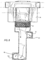
- FIG. 1 shows a pool 10 having a bottom surface 12, a vertical side wall surface 14, water 16 indicated by dashed lines and a top water surface 18. Also shown is a robotic pool cleaner 20 tethered to a remote power supply 8 via a power cable 22.
- the pool cleaner is illustratively shown coupled to a docking station 24 situated at the wall surface 14 near the top water surface 18. Arrows 26 indicate a typical path of the pool cleaner and cleaning along the bottom surface of pool.
- FIG. 1 the pool cleaner 20 is shown in a generally vertical orientation when it is coupled to the docking station 24.
- Arrow 30 indicates the water flow direction into a pre-filter 32 of debris, and arrows 34 indicate subsequent water flow into intake duct 36 of the pool cleaner, a second intake duct being shown more clearly in subsequent views.
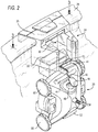
- FIG 2 illustrates the pool cleaner 20 in a generally vertical orientation where it is engaged and coupled to docking station 24 which has been secured onto an upper edge 38 of the pool or secured to another pool structure.
- arrow 30 indicates water descending initially into debris filter 32.
- filter 32 is illustrated as a rectangular perforated bin, although such shape of the bin is not considered limiting as the bin be circular or other shapes.
- Filter 32 captures relatively large articles of debris 32A (see Figure 5 ) such as leaves and twigs, paper, plastic, etc. to prevent them from subsequently entering the pool cleaner and rapidly causing a blockage from the accumulation of debris.
- a fastener of the docking station 24 such as a latch 40 with a hook element 42 that is configured to releasably engage with a catch bar (latch-engaging element) 44 of the cleaner.
- the catch bar 44 is also the pool cleaner carrying handle located at the top forward end of the pool cleaner 20.
- latch 40 is pivoted downwardly about its pivot axis 41 so that hook element 42 partially encircles and captures catch bar 44, thus restraining pool cleaner 20 from dropping downward and away from docking station 24.
- Latch 40 also has an extending member or arm 46 formed as a generally flat panel or paddle that can pivot downward to be adjacent and generally in line with the pool cleaner' s front end water flow outlet duct 48.
- This arm or paddle 46 is discussed below in further detail.
- FIG. 2 Also shown in Figure 2 are front and rear free-wheeling wheels or other rotary support elements 50 which facilitate rolling movement of pool cleaner 20.
- the wheels are not driven by an electric motor and/or transmission. Rather, the wheels rotate freely, since the illustrative pool cleaner 20 is driven forward and rearward by pressurized water jets which are selectively and alternately discharged from the front and rear outlets 48, 52, as discussed below in further detail.
- the docking station 24 is not limited to use with jet driven cleaners, as robotic cleaners which have driven wheels and/or tracks can also be docked and operate in conjunction with the docking station 24 of the present invention in a similar manner as described herein.
- FIG 3 is a sectional view taken along line 3-3 in Figure 2 showing a top plan view with pool cleaner 20 in vertical position coupled to docking station 24. In this view can be seen a portion of debris filter 32 that receives downward descending water as described in connection with Figures 1 and 2 . Also seen in Figure 3 is paddle 46 of latch 40 that becomes aligned with front outlet water flow from duct 48 of the pool cleaner 20.
- Figure 4 is an elevational view corresponding to the perspective elevational view of Figure 2 and the top plan view in Figure 3 , all showing the pool cleaner 20 engaged and coupled to docking station 24.
- pool cleaner 20 with its free-wheeling wheels 50, latch 40, latch arm/paddle 46 engaging the cleaner handle or catch bar 44 which is illustratively adjacent the pool cleaner's front outlet water flow duct 48 of the pool cleaner 20.
- a rear outlet duct 52 Seen in both Figures 4 and 5 is a rear outlet duct 52 opposite front outlet duct 48.
- Figure 4 also shows a generally rectangular or oval breakaway line 54 which is provided in the drawing to expose the central internal chamber 56 which is formed within the housing underneath the top surface of pool cleaner 20.
- an electric motor 62 which drives opposing propellers 58 and 60, preferably from a single drive shaft, although such configuration is not limiting.
- the electric motor 62 and drive shafts extend along the longitudinal axis of the cleaner 20.
- One or more filter bag(s) 66 are disposed in the interior chamber 56 to capture debris entering the chamber from the inlet(s).
- the cleaner 20 is illustratively described as including one or more filter bags, such filter type is not considered limiting as other filters can be implemented in the cleaner including a filter bucket(s), screen mesh containers, filter cartridges, and the like.
- a motor 62 can optionally be generally surrounded by screen 64 for added protection, for example, to ensure that the filter bag(s) 66 cannot interfere with the rotation of propellers 58 and 60.
- screen 64 for added protection, for example, to ensure that the filter bag(s) 66 cannot interfere with the rotation of propellers 58 and 60.
- filter screen 64 and filter bags 66 would be cleaned and/or replaced.
- filter containers with a generally fixed shape filter screen 64 would be unnecessary.
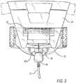
- Figure 5 corresponds in part to Figures 1-4 showing water flow indicated by arrow 28 ( Figs. 1 and 5 ) at the top surface of water 16 in pool 10, which water is flowing to the left as seen and approaching docking station 24 which is engaged near the top edge 38 at the waterline of the pool.
- water descending via arrow 30 toward and into a pre-filter or strainer 32 first passes pivotal panel 70, which generally funnels and/or constricts water flow shown by arrows 72, 73 into a smaller space, with the result that water flow in the area of arrow 30, i.e., over the top edge 70A of the panel 70, flows more rapidly and thereby enhances the carrying or entrainment of debris over edge 70A of panel 70 and downward into pre-filter/strainer 32.
- Panel 70 tends to pivot according to the water level which varies in the pool. For example, panel 70 could pivot downward to the dotted line position 70B if the water level were to drop from the present waterline as illustratively shown in the Figure 5 . Also shown in Figure 5 at the top of debris filter/strainer 32 is a bent twig 32A, which symbolically indicates relatively large debris that will be captured by this filter strainer 32.
- Panel 70 can be configured and constructed to have weight and buoyancy such that its top edge 70A is situated generally near but below the water level top surface 18.
- the height of panel 70 is such that if it is inclined downward to position indicated at 70B, there will remain sufficient space for downward water flow, as illustrated by arrow 32 in Figure 5 .
- this open passage zone for water flow i.e. not fully blocked
- the possibility will be reduced of pump motor 62 of the cleaner 20 being overloaded while trying to suction water through a blocked passage.
- panel 70 will occupy its highly inclined position, allowing a wide opening for water flow into the top filter 32.
- FIG. 5 further shows water flow indicated by arrow 77 exiting filter/ strainer 32 and flowing via arrow 78 into the pool cleaner's front inlet duct 36, and via arrow 80 into rear inlet duct 37.
- Ducts 36 and 37 direct the flow of water and debris directly into the filter bags 66 positioned in the central chamber 56.
- Each duct includes a valve or simple pivotal closure flap such as flap 37F in rear inlet duct 37 and a corresponding flap not seen in front inlet duct 36. These valves prevent or at least restrict backflow.
- the arrow marked 85 indicate a water jet out of the rear duct opening. This occurs when the pump front and rear propellers 58, 60 are rotated in a first rotational direction (e.g., counter-clockwise) causing water jet out of the rear opening. Such pump action would produce suction at the front discharge port; however, inflow of water is blocked by flexible and/or pivotal flap 48A seen in Figures 5 and 6 .
- By closing front outlet water flow duct 48 all the filtered water is discharged as a water jet out of rear outlet water flow duct 52. From this rear end discharge is a secondary benefit of urging the pool cleaner forward and into more secure engagement with the docking station.
- the polarity of motor 62 is reversed to thereby change the rotation of the propellers in an opposite direction (e.g., clockwise), so that water jet is discharged only out of the front outlet 48.
- a similar flexible or pivotal flap valve 52A seen in Figures 4-7 will close the rear end opening 52, seen in Figures 2 and 6 , and will direct filtered water only out of the previously forward outlet opening 48.
- the forward direction that the cleaner moves at a given time determines the nomenclature of the front and rear ends and ports of the cleaner 20.
- the rotating propellers 58 draw water inward through said two inlet ducts 36, 37, past pre-filter 32 in docking station, and past secondary filters filter bags 66 in the cleaner, and thence to front outlet duct 48 or rear outlet duct 52, depending on the direction of rotation of the propellers. As shown in Figures 6 and 7 the flow direction through one or the other of said front and rear outlet ducts will be discussed below as to the effect that such has on the relationship of pool cleaner 22 and the docking station 24.
- FIG 7 is essentially a mirror image of Figure 5 , showing an elevation partially in section of the pool cleaner associated with the docking station.
- the pool cleaner is coupled to the docking station 24 where its handle/catch bar 44 is captured by hook 42, latching the pool cleaner 20 into its removably fixed operational state.
- both Figures 5 and 7 previously described arrows show the flow path of water over top edge 70A of pivot panel 70, downward through filter/strainer 32, further downward into intake ducts 36, 37 of the pool cleaner, thence through filter bags 66, and finally discharged as water jets by propellers 58, 60 to exit via rear outlet duct 52 seen in Figure 6 or via front exit duct 48 as seen in Figure 7 .
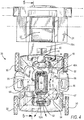
- FIG 8 corresponds to Figure 6 as a front elevational view of the docking station, but is shown with the pool cleaner removed therefrom for clarity of illustration to show the docking station alone.
- the docking station 24 illustratively includes a pair of outlets 76, 76A which are offset from each other and configured to abut against and reside over the corresponding inlets of the cleaner 20.
- the number and configuration of the outlets 76 is not limiting, but is dependent on the number and configuration of the inlets in the cleaner.
- the docking station outlets 76, 76A include a gasket 86 or other sealing element to ensure that water flow directly into the cleaner inlets without leakage back into the pool.
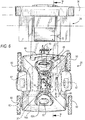
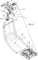
- FIG 9 is an exploded view showing components of the docking station 24 along with ramp 90 by which pool cleaner 20 is directed to move up the ramp.
- the ramp 90 can be wider at it lower end 90A and tapers upwardly in a funnel-like manner towards its top end 90B, which directs pool cleaner 20 to arrive in the orientation and position needed to easily engage and couple with the latch 40 of the docking station.
- Above the ramp and between docking stations outlets 76 and 76A is a guide rail 79A to receive and support wheels 79 of the cleaner when it is docked as seen. Wheels 79 are also visible in Figs. 5 and 7 .
- dashed line is shown the pool cleaner 20B traveling up the ramp 90 by its pressurized water jet flowing out of rear outlet opening 52.
- the cleaner 20 climbs upwards on the ramp 90 until it arrives in its final destination against the bumper 61, and where the cleaner's inlet ducts become aligned with docking station outlets 76 and 76A (see FIG. 5 , 8 and 9 ) in a watertight interface so that pool water flowing into docking station 24 can be directed into pool cleaner filters and then returned as filtered water back into the pool.
- the docking station retains the pool cleaner in a vertical orientation along the sidewall of the pool, and acts as a conduit or duct to allow the flow of water and debris proximate the waterline to be filtered by the cleaner and optionally the docking station itself.
- the cleaner 20 is responsive to command signals from a controller 100 which assists with the cleaning operations of the pool.
- the controller is preferably a micro-controller that can be installed on-board the cleaning device 10. Alternatively, the controller can be installed in an external power supply 102 (seen in Figure 1 ) from which control signals are sent over the power cable electrically coupled between the external power supply and the cleaning device 10.
- the controller generally includes a micro-controller or micro-processor, one or more input/output (I/O interfaces, support circuitry, as well as memory for storing various operational and cleaning programs. Communications between the various microcontroller components are facilitated via one or more bus lines.
- the processor cooperates with conventional support circuitry, such as power supplies, clock circuits, cache memory and the like, as well as circuits that assist in executing software routines stored in the memory.
- the memory can be a single memory device or separate memory devices that function as program storage and data storage.
- the program storage can include one or more cleaning pattern routines and other operational routines.
- the cleaning pattern routines can be preinstalled by the manufacturer with different cleaning patterns and/or durations, and thereafter selectable by the end-user.
- the data storage can include user-input data, such as dimensions/configuration of the pool for which the cleaning device 20 will be used, as well as sensor data, and the like.
- the micro-processor executes a cleaning pattern routine using the pool dimension/configuration data previously inputted into the memory by a field technician or end-user.
- the controller also contains input/output (I/O) circuitry that forms an interface between the various functional elements communicating with the controller.
- I/O input/output
- the microcontroller can send instructions to a switch in communication with the pump motor 62 to reverse polarity and thereby change the rotational direction of the propellers at predetermined times in accordance with the cleaning pattern routines.
- controller discussed as being a microcontroller or a general-purpose computer that is programmed to perform various defined and/or control functions for specific purposes in accordance with the present invention
- the invention can be implemented in hardware such as, for example, an application specific integrated circuit (ASIC).
- ASIC application specific integrated circuit
- the docking station 24 has been disclosed for use with robotic cleaners that are propelled by one or more pressurized water jets, such configuration and cleaner type is not considered limiting.
- the docking station can configured for use with other types of cleaners, such as those driven by wheel or track drives.
- the docking station can be configured for "universal" use for various cleaner models/configurations.
- the docking station can include user-adjustable water flow outlets 76 which can be selectively moved and locked at various positions so as to align with different models of cleaners which have their inlets located in different positions.
- the adjustable outlets can include telescoping ducts that are slidable relative to each other laterally or longitudinally so that the outlets 76 can be aligned over and cover the cleaner inlet(s).
- the outlets 76 can include a selectively closable panel, e.g., slidable or hinged panel to close the outlets 76 to thereby prevent the flow of water into the cleaner. Closing the outlets 76 may be desirable where the user wants to dock the cleaner but allow the water to flow directly through the cleaner 20 inlets, instead of the docking station 24 into the pool cleaner.
Landscapes
- Engineering & Computer Science (AREA)
- Architecture (AREA)
- Civil Engineering (AREA)
- Structural Engineering (AREA)
- Mechanical Engineering (AREA)
- Life Sciences & Earth Sciences (AREA)
- Hydrology & Water Resources (AREA)
- Environmental & Geological Engineering (AREA)
- Water Supply & Treatment (AREA)
- Chemical & Material Sciences (AREA)
- Organic Chemistry (AREA)
- Filtration Of Liquid (AREA)
Claims (20)
- System mit einem Schwimmbeckenreiniger (20) und einer Andockstation (24), wobei die Andockstation an einer Schwimmbeckenstruktur anbringbar ist, um den Schwimmbeckenreiniger (20) lösbar in Eingriff zu nehmen, der in einem Schwimmbecken (10) mit Wasser (16) betrieben werden kann, wobei die Andockstation (24) aufweist:einen Rahmen mit einer darin befindlichen Wasserkammer,ein Befestigungsmittel, um den Schwimmbeckenreiniger (20) lösbar an den Rahmen anzukoppeln, wobei das Befestigungsmittel optional einen offenen und einen geschlossenen Zustand hat, undeinen Kanal mit einem Andockstationseinlass für einen Strom des Schwimmbeckenwassers (16) in die Wasserkammer hinein und einem Andockstationsauslass für einen Strom des Schwimmbeckenwassers (16) aus der Wasserkammer heraus,wobei der Schwimmbeckenreiniger (20) eine Innenkammer mit einem Einlass und einem Ausstoßauslass hat und der Schwimmbeckenreiniger (20) dazu ausgelegt ist, mit der Andockstation (24) in einem Betriebsmodus zusammenzuwirken, in dem der Schwimmbeckenreiniger (24) Schwimmbeckenwasser (16) von der Andockstation (24) einsaugt, filtert und gefiltertes Schwimmbeckenwasser (16) zurück in die Schwimmbeckenstruktur ausstößt.
- System nach Anspruch 1, wobei der Schwimmbeckenreiniger (20) einen aus der Innenkammer herausführenden vorderen und hinteren Ausstoßauslass aufweist und dazu ausgelegt ist, gefiltertes Wasser (16) während des Betriebsmodus von der Innenkammer als hinteren Wasserstrahl durch den hinteren Ausstoßauslass auszustoßen, während der vordere Ausstoßauslass geschlossen ist.
- System nach Anspruch 2, wobei das Befestigungsmittel einen Flügel (46) aufweist, der zwischen dem offenen und geschlossenen Zustand bewegbar ist.
- System nach Anspruch 1, wobei der Schwimmbeckenreiniger (20) im Betriebsmodus an die Andockstation (24) in einer Ausrichtung angekoppelt ist, in der der Einlass des Schwimmbeckenreinigers mit dem Andockstationsauslass ausgerichtet ist, so dass eine Wasserpumpe im Schwimmbeckenreiniger (20) Wasser (16) in und durch die Wasserkammer der Andockstation und in und durch den Filter des Schwimmbeckenreinigers saugen und danach gefiltertes Wasser (16) durch einen ausgewählten Ausstoßauslass des Schwimmbeckenreinigers ausstoßen kann.
- System nach Anspruch 4, darüber hinaus mit einem Vorfilter in dem Rahmen, wobei die Wasserpumpe im Schwimmbeckenreiniger (20) Wasser (16) durch den Vorfilter saugen kann, bevor das Wasser (16) in den Schwimmbeckenreiniger (20) eintritt.
- System nach Anspruch 1, darüber hinaus mit einer Andockstations-Einlassdrossel, die einstellbar ist, um die Geschwindigkeit des Schwimmbeckenwassers (16) zu verändern, das in die Wasserkammer der Andockstation (24) eingesaugt wird.
- System nach Anspruch 6, wobei die Andockstations-Einlassdrossel den Andockstationseinlass verengt, um die Geschwindigkeit des Wasserstroms des Schwimmbeckenwassers (16) zu erhöhen, der in die Wasserkammer in der Andockstation (24) eintritt.
- System nach Anspruch 6, wobei die Einlassdrossel eine Platte aufweist, die einen oberen und einen unteren Abschnitt hat und um den unteren Abschnitt schwenkbar ist und eine Auftriebskraft aufweist, so dass der obere Abschnitt dazu tendiert, unterhalb der oberen Oberfläche des in den Einlass der Andockstation (24) führenden Wasserstroms des Schwimmbeckenwassers (16) positioniert zu sein.
- System nach Anspruch 1, wobei der Wasserstrom in den Andockstationseinlass dadurch zustande kommt, dass Wasser (16) durch den Schwimmbeckenreiniger (20) in und durch die Andockstation (24) und in den Einlass des Schwimmbeckenreinigers gepumpt wird, wenn sich der Schwimmbeckenreiniger (20) im Betriebsmodus befindet.
- System nach Anspruch 1, darüber hinaus mit einer gekrümmten Rampe mit einem proximalen Abschnitt, der sich vom Rahmen nach unten erstreckt, und einem distalen Abschnitt, der quer verläuft und eine Breitenabmessung hat, die breiter als die Breitenabmessung des Schwimmbeckenreinigers (20) ist, wobei der proximale Abschnitt dazu ausgelegt ist, den Schwimmbeckenreiniger (20) aufzunehmen und zu positionieren, wenn er sich an der Rampe nach oben bewegt, so dass der Einlass des Schwimmbeckenreinigers mit dem Andockstationsauslass ausgerichtet ist und ein vorderer Abschnitt des Schwimmbeckenreinigers (20) am Befestigungsmittel anliegt.
- System nach Anspruch 1, darüber hinaus mit einer gekrümmten Rampe mit einem proximalen Abschnitt, der sich vom Rahmen allgemein vertikal nach unten erstreckt, und einem distalen Abschnitt, der allgemein horizontal verläuft, wobei der Schwimmbeckenreiniger (20), von seiner Steuerung angesteuert, auf den distalen Teil der Rampe getrieben werden kann, unter Führung auf der Rampe an dieser hochrollen und sich dann an die Andockstation (24) ankoppeln kann.
- System nach Anspruch 1, wobei der Schwimmbeckenreiniger (20) zwei voneinander beabstandete Einlässe hat und die Andockstation (24) zwei Auslässe aufweist, die ähnlich beabstandet wie die voneinander beabstandeten Einlässe des Schwimmbeckenreinigers (20) sind, und die Einlässe des Schwimmbeckenreinigers (20), wenn er an die Andockstation (24) angekoppelt ist, mit den Andockstationsauslässen ausgerichtet sind, so dass Wasser (16) durch die Wasserpumpe des Schwimmbeckenreinigers (20) aus der Wasserkammer der Andockstation angesaugt wird und in die Innenkammer des Schwimmbeckenreinigers (20) einströmt.
- Verfahren zum Filtern von Wasser (16) in einem Schwimmbecken (10) mithilfe eines Schwimmbeckenreinigers (20), umfassend:(i) einen Körper mit einem vorderen und hinteren Abschnitt sowie einem unteren Abschnitt, (ii) eine interne Kammer, die eine Wasserpumpe und einen Wasserfilter enthält, wobei die interne Kammer im vorderen und hinteren Abschnitt des Körpers eine vordere Ausstoßöffnung bzw. eine hintere Ausstoßöffnung aufweist, und mit einem Einlass im unteren Abschnitt und jeweils einem Ventil für die vordere und hintere Öffnung, und (iii) eine programmierbare Steuerung, die dazu ausgelegt ist, die Wasserpumpe zu betätigen, um gefiltertes Wasser (16) wahlweise durch die vordere oder hintere Öffnung zu leiten, wobei jedes der Ventile aufmachen kann, wenn ein Wasserstrahl aus der vorderen und hinteren Ausstoßöffnung herausgepumpt wird, wobei das Verfahren folgende Schritte umfasst:Anbringen einer Andockstation (24) an einer Schwimmbeckenstruktur, wobei die Andockstation (24) einen Andockstationseinlass und einen Andockstationsauslass aufweist und die Andockstation (24) so ausgelegt ist, dass der Andockstationseinlass unterhalb eines oberen Wasserpegels des Schwimmbeckenwassers (16) positioniert ist,Aufnehmen und lösbares Ankoppeln des Schwimmbeckenreinigers (20) an die Andockstation (24), und,durch die Steuerung angesteuert, Betreiben der Wasserpumpe in dem Schwimmbeckenreiniger (20), um Schwimmbeckenwasser (16) durch die Andockstation (24) und in und durch den Wasserfilter im Schwimmbeckenreiniger (20) zu saugen und gefiltertes Wasser (16) zurück in das Schwimmbecken (10) auszustoßen.
- Verfahren zum Filtern von Wasser (16) in einem Schwimmbecken (10) nach Anspruch 13, wobei der Schritt des Aufnehmens und lösbaren Ankoppelns umfasst, den Einlass des Schwimmbeckenreinigers so zu positionieren, dass er mit dem Andockstationsauslass ausgerichtet ist.
- Verfahren zum Filtern von Wasser (16) in einem Schwimmbecken (10) nach Anspruch 14, wobei der Schwimmbeckenreiniger (20) dazu ausgelegt ist, mit der Andockstation (24) in einem ersten Betriebsmodus, in dem der Schwimmbeckenreiniger inaktiv ist, oder einem zweiten Betriebsmodus, in dem der Schwimmbeckenreiniger (20) Schwimmbeckenwasser (16) von der Andockstation (24) her ansaugt, filtert und das gefilterte Schwimmbeckenwasser (16) zurück in das Schwimmbecken (10) ausstößt, oder in einem dritten Betriebsmodus zusammenzuwirken, in dem sich der Schwimmbeckenreiniger von der Andockstation abkoppelt.
- Verfahren zum Filtern von Wasser (16) in einem Schwimmbecken (10) nach Anspruch 13, wobei das Aufnehmen und lösbare Ankoppeln des Schwimmbeckenreinigers (20) an die Andockstation (24) umfasst, ein Befestigungsmittel für ein lösbares Angreifen am Schwimmbeckenreiniger (20) zu verwenden.
- Verfahren zum Filtern von Wasser (16) in einem Schwimmbecken (10) nach Anspruch 16, wobei das lösbare Befestigungsmittel des Schwimmbeckenreinigers einen schwenkbaren Flügel aufweist und das Abkoppeln im dritten Betriebsmodus umfasst, die Wasserpumpe so anzusteuern, dass sie einen Wasserstrahl in einer Vorwärtsrichtung ausstößt, der auf den Flügel trifft und ihn in einen offenen Zustand verschwenkt, um den Schwimmbeckenreiniger (20) von der Andockstation (24) zu lösen.
- Verfahren zum Filtern von Wasser (16) in einem Schwimmbecken (10) nach Anspruch 13, darüber hinaus umfassend, groben Schmutz herauszufiltern, bevor er in den Andockstationseinlass eintritt, indem ein Filter im Pfad des in den Andockstationseinlass führenden Wasserstroms positioniert wird.
- Verfahren zum Filtern von Wasser (16) in einem Schwimmbecken (10) nach Anspruch 18, darüber hinaus aufweisend, eine Einlassdrossel am Andockstationseinlass vorzusehen, um den Wasserstrompfad zu reduzieren und dadurch die Geschwindigkeit des Schwimmbeckenwassers (16) zu erhöhen, um herauszufilternden Schmutz besser mitreißen zu können.
- Verfahren zum Filtern von Wasser (16) in einem Schwimmbecken (10) nach Anspruch 19, wobei das Vorsehen der Einlassdrossel umfasst, eine Barriere in einem Bereich vorzusehen, in dem Schwimmbeckenwasser in den Andockstationseinlass einströmt, wobei die Barriere eine Auftriebskraft hat, so dass sie stets den Wasserstrom hemmt, mit Ausnahme des Wassers, das über einen oberen Abschnitt der Barriere fließt, und die Barriere aufgrund ihrer Auftriebskraft den oberen Abschnitt stets geringfügig unterhalb der oberen Oberfläche des fließenden Wassers liegen hat.
Applications Claiming Priority (2)
| Application Number | Priority Date | Filing Date | Title |
|---|---|---|---|
| US201562169963P | 2015-06-02 | 2015-06-02 | |
| PCT/US2016/035251 WO2016196622A1 (en) | 2015-06-02 | 2016-06-01 | Docking station for a pool cleaner in a pool |
Publications (4)
| Publication Number | Publication Date |
|---|---|
| EP3303733A1 EP3303733A1 (de) | 2018-04-11 |
| EP3303733A4 EP3303733A4 (de) | 2019-02-27 |
| EP3303733B1 true EP3303733B1 (de) | 2020-12-16 |
| EP3303733B8 EP3303733B8 (de) | 2021-03-17 |
Family
ID=57441666
Family Applications (1)
| Application Number | Title | Priority Date | Filing Date |
|---|---|---|---|
| EP16804326.3A Active EP3303733B8 (de) | 2015-06-02 | 2016-06-01 | System bestehend aus einem schwimmbeckenreiniger und andockstation in einem schwimmbecken |
Country Status (4)
| Country | Link |
|---|---|
| US (1) | US10450769B2 (de) |
| EP (1) | EP3303733B8 (de) |
| ES (1) | ES2850080T3 (de) |
| WO (1) | WO2016196622A1 (de) |
Families Citing this family (17)
| Publication number | Priority date | Publication date | Assignee | Title |
|---|---|---|---|---|
| US10723571B2 (en) | 2013-10-13 | 2020-07-28 | Maytronics Ltd | Pool cleaning robot having an interface |
| US9920545B2 (en) | 2013-10-13 | 2018-03-20 | Maytronics Ltd. | Autonomous pool cleaning robot |
| DE102016124674A1 (de) * | 2016-12-16 | 2018-06-21 | Vorwerk & Co. Interholding Gmbh | Selbsttätig fortbewegbares Reinigungsgerät |
| US10364905B2 (en) | 2017-05-11 | 2019-07-30 | Hayward Industries, Inc. | Pool cleaner check valve |
| US10214933B2 (en) | 2017-05-11 | 2019-02-26 | Hayward Industries, Inc. | Pool cleaner power supply |
| WO2019053801A1 (ja) * | 2017-09-13 | 2019-03-21 | 学校法人 千葉工業大学 | 自走式掃除機 |
| US11980334B2 (en) | 2017-09-15 | 2024-05-14 | Omachron Intellectual Property Inc. | Surface cleaning apparatus |
| ES2991911T3 (es) * | 2018-01-04 | 2024-12-05 | Zodiac Pool Systems Llc | Limpiador automático de piscinas |
| CN114557630B (zh) * | 2018-10-22 | 2023-12-29 | 奥马克罗知识产权有限公司 | 空气处理装置 |
| IT202100006875A1 (it) * | 2021-03-22 | 2022-09-22 | Fabrizio Bernini | Sistema di pulizia per piscine |
| CN116290947A (zh) * | 2021-12-11 | 2023-06-23 | 天津望圆智能科技股份有限公司 | 一种水下对接站 |
| CN114652236B (zh) * | 2022-03-02 | 2023-07-28 | 深圳市杉川机器人有限公司 | 机器人基站和清洁系统 |
| US20240269860A1 (en) * | 2023-02-09 | 2024-08-15 | Ecoserv Technologies, Llc | Compact robotic cleaner for hazardous environments |
| US20250012107A1 (en) * | 2023-07-06 | 2025-01-09 | Hayward Industries, Inc. | Automatic Pool/Spa Cleaner With Wall Docking Feature |
| US12416174B2 (en) | 2023-09-20 | 2025-09-16 | Maytronics Ltd. | Wireless based pick-up and in pool navigation |
| WO2025232729A1 (zh) * | 2024-05-09 | 2025-11-13 | 天津望圆智能科技股份有限公司 | 一种水池清洁系统 |
| CN118558692B (zh) * | 2024-07-31 | 2024-10-15 | 无棣县润禹水务集团有限公司 | 一种自来水厂青苔清洗装置 |
Family Cites Families (7)
| Publication number | Priority date | Publication date | Assignee | Title |
|---|---|---|---|---|
| US6652742B2 (en) | 2000-11-14 | 2003-11-25 | Melvyn L. Henkin | Automatic pool cleaner system utilizing electric and suction power |
| AUPS159302A0 (en) * | 2002-04-09 | 2002-05-16 | Haski, Robert R. | Water skimmer |
| WO2014097304A1 (en) | 2012-12-22 | 2014-06-26 | Maytronics Ltd. | Autonomous pool cleaning robot |
| EP2669450B1 (de) | 2012-05-30 | 2015-04-01 | Fabrizio Bernini | Vorrichtung zum Reinigen von Schwimmbecken |
| US9903130B2 (en) * | 2012-12-22 | 2018-02-27 | Maytronics Ltd. | Autonomous pool cleaning robot with an external docking station |
| US20140263087A1 (en) | 2013-03-15 | 2014-09-18 | Hayward Industries, Inc. | Swimming Pool Cleaner With Docking System And/Or Other Related Systems And Methods |
| US9920545B2 (en) | 2013-10-13 | 2018-03-20 | Maytronics Ltd. | Autonomous pool cleaning robot |
-
2016
- 2016-06-01 US US15/578,572 patent/US10450769B2/en active Active
- 2016-06-01 ES ES16804326T patent/ES2850080T3/es active Active
- 2016-06-01 WO PCT/US2016/035251 patent/WO2016196622A1/en not_active Ceased
- 2016-06-01 EP EP16804326.3A patent/EP3303733B8/de active Active
Non-Patent Citations (1)
| Title |
|---|
| None * |
Also Published As
| Publication number | Publication date |
|---|---|
| EP3303733B8 (de) | 2021-03-17 |
| ES2850080T3 (es) | 2021-08-25 |
| EP3303733A4 (de) | 2019-02-27 |
| US10450769B2 (en) | 2019-10-22 |
| EP3303733A1 (de) | 2018-04-11 |
| WO2016196622A1 (en) | 2016-12-08 |
| US20180155946A1 (en) | 2018-06-07 |
Similar Documents
| Publication | Publication Date | Title |
|---|---|---|
| EP3303733B1 (de) | System bestehend aus einem schwimmbeckenreiniger und andockstation in einem schwimbecken | |
| US9091093B2 (en) | Internal backwash system for robotic swimming pool cleaner | |
| JP7342061B2 (ja) | 清掃ロボット用デブリ排出 | |
| US11802418B2 (en) | Swimming pool cleaning device including a removable filter device | |
| US8555445B2 (en) | Hydraulic driven jaw-type clutch impeller combination and swimming pool bottom hydraulic pushed automatic cleaner comprising same | |
| EP2570570B1 (de) | Schwimmbeckenreinigungsroboter | |
| ES2745040T3 (es) | Limpiador de piscinas robótico autopropulsado con boya de flotación con amarre retráctil | |
| ES2991911T3 (es) | Limpiador automático de piscinas | |
| AU2019236716B2 (en) | Pool cleaner | |
| EP3788216B1 (de) | Automatischer schwimmbeckenreiniger mit kanteneingriffsanordnung | |
| ES2685589T3 (es) | Limpiador de piscinas superior/inferior eléctrico y automático con bombas internas | |
| US20050015916A1 (en) | Wet-dry vacuum cleaning device | |
| US20240172909A1 (en) | Surface cleaning apparatus | |
| US20050279682A1 (en) | Debris bag for a swimming pool cleaning apparatus | |
| US20120192376A1 (en) | Apparatus For Clearing Waste From A Surface | |
| US20250018320A1 (en) | Portable fluid filtering apparatus | |
| AU2022358788B2 (en) | Surface cleaning apparatus | |
| CN223773647U (zh) | 一种尘盒、吸尘装置、清洁设备及清洁系统 | |
| CN215272447U (zh) | 吸尘器 | |
| JP2005021850A (ja) | 遮風装置 | |
| CN119769934A (zh) | 一种尘盒、吸尘装置、清洁设备及清洁系统 |
Legal Events
| Date | Code | Title | Description |
|---|---|---|---|
| STAA | Information on the status of an ep patent application or granted ep patent |
Free format text: STATUS: THE INTERNATIONAL PUBLICATION HAS BEEN MADE |
|
| PUAI | Public reference made under article 153(3) epc to a published international application that has entered the european phase |
Free format text: ORIGINAL CODE: 0009012 |
|
| STAA | Information on the status of an ep patent application or granted ep patent |
Free format text: STATUS: REQUEST FOR EXAMINATION WAS MADE |
|
| 17P | Request for examination filed |
Effective date: 20180102 |
|
| AK | Designated contracting states |
Kind code of ref document: A1 Designated state(s): AL AT BE BG CH CY CZ DE DK EE ES FI FR GB GR HR HU IE IS IT LI LT LU LV MC MK MT NL NO PL PT RO RS SE SI SK SM TR |
|
| AX | Request for extension of the european patent |
Extension state: BA ME |
|
| DAV | Request for validation of the european patent (deleted) | ||
| DAX | Request for extension of the european patent (deleted) | ||
| A4 | Supplementary search report drawn up and despatched |
Effective date: 20190129 |
|
| RIC1 | Information provided on ipc code assigned before grant |
Ipc: E04H 4/16 20060101AFI20190123BHEP Ipc: B08B 1/02 20060101ALI20190123BHEP Ipc: B25J 11/00 20060101ALI20190123BHEP Ipc: B25J 5/00 20060101ALI20190123BHEP |
|
| GRAP | Despatch of communication of intention to grant a patent |
Free format text: ORIGINAL CODE: EPIDOSNIGR1 |
|
| STAA | Information on the status of an ep patent application or granted ep patent |
Free format text: STATUS: GRANT OF PATENT IS INTENDED |
|
| RIC1 | Information provided on ipc code assigned before grant |
Ipc: B08B 9/093 20060101ALI20200214BHEP Ipc: B25J 5/00 20060101ALI20200214BHEP Ipc: E04H 4/12 20060101ALI20200214BHEP Ipc: B08B 1/02 20060101ALI20200214BHEP Ipc: B25J 11/00 20060101ALI20200214BHEP Ipc: E04H 4/16 20060101AFI20200214BHEP |
|
| INTG | Intention to grant announced |
Effective date: 20200319 |
|
| GRAJ | Information related to disapproval of communication of intention to grant by the applicant or resumption of examination proceedings by the epo deleted |
Free format text: ORIGINAL CODE: EPIDOSDIGR1 |
|
| STAA | Information on the status of an ep patent application or granted ep patent |
Free format text: STATUS: REQUEST FOR EXAMINATION WAS MADE |
|
| INTC | Intention to grant announced (deleted) | ||
| GRAP | Despatch of communication of intention to grant a patent |
Free format text: ORIGINAL CODE: EPIDOSNIGR1 |
|
| STAA | Information on the status of an ep patent application or granted ep patent |
Free format text: STATUS: GRANT OF PATENT IS INTENDED |
|
| INTG | Intention to grant announced |
Effective date: 20200715 |
|
| RAP1 | Party data changed (applicant data changed or rights of an application transferred) |
Owner name: ZODIAC POOL SYSTEMS LLC |
|
| GRAS | Grant fee paid |
Free format text: ORIGINAL CODE: EPIDOSNIGR3 |
|
| GRAA | (expected) grant |
Free format text: ORIGINAL CODE: 0009210 |
|
| STAA | Information on the status of an ep patent application or granted ep patent |
Free format text: STATUS: THE PATENT HAS BEEN GRANTED |
|
| AK | Designated contracting states |
Kind code of ref document: B1 Designated state(s): AL AT BE BG CH CY CZ DE DK EE ES FI FR GB GR HR HU IE IS IT LI LT LU LV MC MK MT NL NO PL PT RO RS SE SI SK SM TR |
|
| REG | Reference to a national code |
Ref country code: GB Ref legal event code: FG4D |
|
| REG | Reference to a national code |
Ref country code: IE Ref legal event code: FG4D |
|
| REG | Reference to a national code |
Ref country code: DE Ref legal event code: R096 Ref document number: 602016049962 Country of ref document: DE |
|
| REG | Reference to a national code |
Ref country code: AT Ref legal event code: REF Ref document number: 1345731 Country of ref document: AT Kind code of ref document: T Effective date: 20210115 Ref country code: CH Ref legal event code: PK Free format text: TITEL |
|
| REG | Reference to a national code |
Ref country code: CH Ref legal event code: PK Free format text: BERICHTIGUNG B8 |
|
| PG25 | Lapsed in a contracting state [announced via postgrant information from national office to epo] |
Ref country code: RS Free format text: LAPSE BECAUSE OF FAILURE TO SUBMIT A TRANSLATION OF THE DESCRIPTION OR TO PAY THE FEE WITHIN THE PRESCRIBED TIME-LIMIT Effective date: 20201216 Ref country code: NO Free format text: LAPSE BECAUSE OF FAILURE TO SUBMIT A TRANSLATION OF THE DESCRIPTION OR TO PAY THE FEE WITHIN THE PRESCRIBED TIME-LIMIT Effective date: 20210316 Ref country code: FI Free format text: LAPSE BECAUSE OF FAILURE TO SUBMIT A TRANSLATION OF THE DESCRIPTION OR TO PAY THE FEE WITHIN THE PRESCRIBED TIME-LIMIT Effective date: 20201216 Ref country code: GR Free format text: LAPSE BECAUSE OF FAILURE TO SUBMIT A TRANSLATION OF THE DESCRIPTION OR TO PAY THE FEE WITHIN THE PRESCRIBED TIME-LIMIT Effective date: 20210317 |
|
| REG | Reference to a national code |
Ref country code: AT Ref legal event code: MK05 Ref document number: 1345731 Country of ref document: AT Kind code of ref document: T Effective date: 20201216 |
|
| REG | Reference to a national code |
Ref country code: NL Ref legal event code: MP Effective date: 20201216 |
|
| PG25 | Lapsed in a contracting state [announced via postgrant information from national office to epo] |
Ref country code: SE Free format text: LAPSE BECAUSE OF FAILURE TO SUBMIT A TRANSLATION OF THE DESCRIPTION OR TO PAY THE FEE WITHIN THE PRESCRIBED TIME-LIMIT Effective date: 20201216 Ref country code: LV Free format text: LAPSE BECAUSE OF FAILURE TO SUBMIT A TRANSLATION OF THE DESCRIPTION OR TO PAY THE FEE WITHIN THE PRESCRIBED TIME-LIMIT Effective date: 20201216 Ref country code: BG Free format text: LAPSE BECAUSE OF FAILURE TO SUBMIT A TRANSLATION OF THE DESCRIPTION OR TO PAY THE FEE WITHIN THE PRESCRIBED TIME-LIMIT Effective date: 20210316 |
|
| PG25 | Lapsed in a contracting state [announced via postgrant information from national office to epo] |
Ref country code: NL Free format text: LAPSE BECAUSE OF FAILURE TO SUBMIT A TRANSLATION OF THE DESCRIPTION OR TO PAY THE FEE WITHIN THE PRESCRIBED TIME-LIMIT Effective date: 20201216 Ref country code: HR Free format text: LAPSE BECAUSE OF FAILURE TO SUBMIT A TRANSLATION OF THE DESCRIPTION OR TO PAY THE FEE WITHIN THE PRESCRIBED TIME-LIMIT Effective date: 20201216 |
|
| REG | Reference to a national code |
Ref country code: LT Ref legal event code: MG9D |
|
| PG25 | Lapsed in a contracting state [announced via postgrant information from national office to epo] |
Ref country code: CZ Free format text: LAPSE BECAUSE OF FAILURE TO SUBMIT A TRANSLATION OF THE DESCRIPTION OR TO PAY THE FEE WITHIN THE PRESCRIBED TIME-LIMIT Effective date: 20201216 Ref country code: EE Free format text: LAPSE BECAUSE OF FAILURE TO SUBMIT A TRANSLATION OF THE DESCRIPTION OR TO PAY THE FEE WITHIN THE PRESCRIBED TIME-LIMIT Effective date: 20201216 Ref country code: SM Free format text: LAPSE BECAUSE OF FAILURE TO SUBMIT A TRANSLATION OF THE DESCRIPTION OR TO PAY THE FEE WITHIN THE PRESCRIBED TIME-LIMIT Effective date: 20201216 Ref country code: LT Free format text: LAPSE BECAUSE OF FAILURE TO SUBMIT A TRANSLATION OF THE DESCRIPTION OR TO PAY THE FEE WITHIN THE PRESCRIBED TIME-LIMIT Effective date: 20201216 Ref country code: PT Free format text: LAPSE BECAUSE OF FAILURE TO SUBMIT A TRANSLATION OF THE DESCRIPTION OR TO PAY THE FEE WITHIN THE PRESCRIBED TIME-LIMIT Effective date: 20210416 Ref country code: RO Free format text: LAPSE BECAUSE OF FAILURE TO SUBMIT A TRANSLATION OF THE DESCRIPTION OR TO PAY THE FEE WITHIN THE PRESCRIBED TIME-LIMIT Effective date: 20201216 Ref country code: SK Free format text: LAPSE BECAUSE OF FAILURE TO SUBMIT A TRANSLATION OF THE DESCRIPTION OR TO PAY THE FEE WITHIN THE PRESCRIBED TIME-LIMIT Effective date: 20201216 |
|
| REG | Reference to a national code |
Ref country code: ES Ref legal event code: FG2A Ref document number: 2850080 Country of ref document: ES Kind code of ref document: T3 Effective date: 20210825 |
|
| PG25 | Lapsed in a contracting state [announced via postgrant information from national office to epo] |
Ref country code: AT Free format text: LAPSE BECAUSE OF FAILURE TO SUBMIT A TRANSLATION OF THE DESCRIPTION OR TO PAY THE FEE WITHIN THE PRESCRIBED TIME-LIMIT Effective date: 20201216 Ref country code: PL Free format text: LAPSE BECAUSE OF FAILURE TO SUBMIT A TRANSLATION OF THE DESCRIPTION OR TO PAY THE FEE WITHIN THE PRESCRIBED TIME-LIMIT Effective date: 20201216 |
|
| REG | Reference to a national code |
Ref country code: DE Ref legal event code: R097 Ref document number: 602016049962 Country of ref document: DE |
|
| PG25 | Lapsed in a contracting state [announced via postgrant information from national office to epo] |
Ref country code: IS Free format text: LAPSE BECAUSE OF FAILURE TO SUBMIT A TRANSLATION OF THE DESCRIPTION OR TO PAY THE FEE WITHIN THE PRESCRIBED TIME-LIMIT Effective date: 20210416 |
|
| PLBE | No opposition filed within time limit |
Free format text: ORIGINAL CODE: 0009261 |
|
| STAA | Information on the status of an ep patent application or granted ep patent |
Free format text: STATUS: NO OPPOSITION FILED WITHIN TIME LIMIT |
|
| PG25 | Lapsed in a contracting state [announced via postgrant information from national office to epo] |
Ref country code: IT Free format text: LAPSE BECAUSE OF FAILURE TO SUBMIT A TRANSLATION OF THE DESCRIPTION OR TO PAY THE FEE WITHIN THE PRESCRIBED TIME-LIMIT Effective date: 20201216 Ref country code: AL Free format text: LAPSE BECAUSE OF FAILURE TO SUBMIT A TRANSLATION OF THE DESCRIPTION OR TO PAY THE FEE WITHIN THE PRESCRIBED TIME-LIMIT Effective date: 20201216 |
|
| 26N | No opposition filed |
Effective date: 20210917 |
|
| PG25 | Lapsed in a contracting state [announced via postgrant information from national office to epo] |
Ref country code: DK Free format text: LAPSE BECAUSE OF FAILURE TO SUBMIT A TRANSLATION OF THE DESCRIPTION OR TO PAY THE FEE WITHIN THE PRESCRIBED TIME-LIMIT Effective date: 20201216 |
|
| PG25 | Lapsed in a contracting state [announced via postgrant information from national office to epo] |
Ref country code: MC Free format text: LAPSE BECAUSE OF FAILURE TO SUBMIT A TRANSLATION OF THE DESCRIPTION OR TO PAY THE FEE WITHIN THE PRESCRIBED TIME-LIMIT Effective date: 20201216 |
|
| REG | Reference to a national code |
Ref country code: CH Ref legal event code: PL |
|
| GBPC | Gb: european patent ceased through non-payment of renewal fee |
Effective date: 20210601 |
|
| PG25 | Lapsed in a contracting state [announced via postgrant information from national office to epo] |
Ref country code: SI Free format text: LAPSE BECAUSE OF FAILURE TO SUBMIT A TRANSLATION OF THE DESCRIPTION OR TO PAY THE FEE WITHIN THE PRESCRIBED TIME-LIMIT Effective date: 20201216 |
|
| REG | Reference to a national code |
Ref country code: BE Ref legal event code: MM Effective date: 20210630 |
|
| PG25 | Lapsed in a contracting state [announced via postgrant information from national office to epo] |
Ref country code: LU Free format text: LAPSE BECAUSE OF NON-PAYMENT OF DUE FEES Effective date: 20210601 |
|
| PG25 | Lapsed in a contracting state [announced via postgrant information from national office to epo] |
Ref country code: LI Free format text: LAPSE BECAUSE OF NON-PAYMENT OF DUE FEES Effective date: 20210630 Ref country code: IE Free format text: LAPSE BECAUSE OF NON-PAYMENT OF DUE FEES Effective date: 20210601 Ref country code: GB Free format text: LAPSE BECAUSE OF NON-PAYMENT OF DUE FEES Effective date: 20210601 Ref country code: CH Free format text: LAPSE BECAUSE OF NON-PAYMENT OF DUE FEES Effective date: 20210630 |
|
| PG25 | Lapsed in a contracting state [announced via postgrant information from national office to epo] |
Ref country code: IS Free format text: LAPSE BECAUSE OF FAILURE TO SUBMIT A TRANSLATION OF THE DESCRIPTION OR TO PAY THE FEE WITHIN THE PRESCRIBED TIME-LIMIT Effective date: 20210416 |
|
| PG25 | Lapsed in a contracting state [announced via postgrant information from national office to epo] |
Ref country code: BE Free format text: LAPSE BECAUSE OF NON-PAYMENT OF DUE FEES Effective date: 20210630 |
|
| PG25 | Lapsed in a contracting state [announced via postgrant information from national office to epo] |
Ref country code: HU Free format text: LAPSE BECAUSE OF FAILURE TO SUBMIT A TRANSLATION OF THE DESCRIPTION OR TO PAY THE FEE WITHIN THE PRESCRIBED TIME-LIMIT; INVALID AB INITIO Effective date: 20160601 |
|
| PG25 | Lapsed in a contracting state [announced via postgrant information from national office to epo] |
Ref country code: CY Free format text: LAPSE BECAUSE OF FAILURE TO SUBMIT A TRANSLATION OF THE DESCRIPTION OR TO PAY THE FEE WITHIN THE PRESCRIBED TIME-LIMIT Effective date: 20201216 |
|
| P01 | Opt-out of the competence of the unified patent court (upc) registered |
Effective date: 20230526 |
|
| PG25 | Lapsed in a contracting state [announced via postgrant information from national office to epo] |
Ref country code: MK Free format text: LAPSE BECAUSE OF FAILURE TO SUBMIT A TRANSLATION OF THE DESCRIPTION OR TO PAY THE FEE WITHIN THE PRESCRIBED TIME-LIMIT Effective date: 20201216 |
|
| PG25 | Lapsed in a contracting state [announced via postgrant information from national office to epo] |
Ref country code: TR Free format text: LAPSE BECAUSE OF FAILURE TO SUBMIT A TRANSLATION OF THE DESCRIPTION OR TO PAY THE FEE WITHIN THE PRESCRIBED TIME-LIMIT Effective date: 20201216 |
|
| PG25 | Lapsed in a contracting state [announced via postgrant information from national office to epo] |
Ref country code: MT Free format text: LAPSE BECAUSE OF FAILURE TO SUBMIT A TRANSLATION OF THE DESCRIPTION OR TO PAY THE FEE WITHIN THE PRESCRIBED TIME-LIMIT Effective date: 20201216 |
|
| PGFP | Annual fee paid to national office [announced via postgrant information from national office to epo] |
Ref country code: DE Payment date: 20250627 Year of fee payment: 10 |
|
| PGFP | Annual fee paid to national office [announced via postgrant information from national office to epo] |
Ref country code: FR Payment date: 20250625 Year of fee payment: 10 |
|
| PGFP | Annual fee paid to national office [announced via postgrant information from national office to epo] |
Ref country code: ES Payment date: 20250701 Year of fee payment: 10 |