EP3303742B1 - Procédé de commande d'une serrure de porte de véhicule - Google Patents
Procédé de commande d'une serrure de porte de véhicule Download PDFInfo
- Publication number
- EP3303742B1 EP3303742B1 EP16736774.7A EP16736774A EP3303742B1 EP 3303742 B1 EP3303742 B1 EP 3303742B1 EP 16736774 A EP16736774 A EP 16736774A EP 3303742 B1 EP3303742 B1 EP 3303742B1
- Authority
- EP
- European Patent Office
- Prior art keywords
- lever
- locking mechanism
- sensor
- child safety
- activated
- Prior art date
- Legal status (The legal status is an assumption and is not a legal conclusion. Google has not performed a legal analysis and makes no representation as to the accuracy of the status listed.)
- Active
Links
Images


Classifications
-
- E—FIXED CONSTRUCTIONS
- E05—LOCKS; KEYS; WINDOW OR DOOR FITTINGS; SAFES
- E05B—LOCKS; ACCESSORIES THEREFOR; HANDCUFFS
- E05B77/00—Vehicle locks characterised by special functions or purposes
- E05B77/22—Functions related to actuation of locks from the passenger compartment of the vehicle
- E05B77/24—Functions related to actuation of locks from the passenger compartment of the vehicle preventing use of an inner door handle, sill button, lock knob or the like
- E05B77/26—Functions related to actuation of locks from the passenger compartment of the vehicle preventing use of an inner door handle, sill button, lock knob or the like specially adapted for child safety
-
- E—FIXED CONSTRUCTIONS
- E05—LOCKS; KEYS; WINDOW OR DOOR FITTINGS; SAFES
- E05B—LOCKS; ACCESSORIES THEREFOR; HANDCUFFS
- E05B81/00—Power-actuated vehicle locks
- E05B81/12—Power-actuated vehicle locks characterised by the function or purpose of the powered actuators
- E05B81/14—Power-actuated vehicle locks characterised by the function or purpose of the powered actuators operating on bolt detents, e.g. for unlatching the bolt
-
- E—FIXED CONSTRUCTIONS
- E05—LOCKS; KEYS; WINDOW OR DOOR FITTINGS; SAFES
- E05B—LOCKS; ACCESSORIES THEREFOR; HANDCUFFS
- E05B81/00—Power-actuated vehicle locks
- E05B81/12—Power-actuated vehicle locks characterised by the function or purpose of the powered actuators
- E05B81/16—Power-actuated vehicle locks characterised by the function or purpose of the powered actuators operating on locking elements for locking or unlocking action
-
- E—FIXED CONSTRUCTIONS
- E05—LOCKS; KEYS; WINDOW OR DOOR FITTINGS; SAFES
- E05B—LOCKS; ACCESSORIES THEREFOR; HANDCUFFS
- E05B81/00—Power-actuated vehicle locks
- E05B81/12—Power-actuated vehicle locks characterised by the function or purpose of the powered actuators
- E05B81/20—Power-actuated vehicle locks characterised by the function or purpose of the powered actuators for assisting final closing or for initiating opening
-
- E—FIXED CONSTRUCTIONS
- E05—LOCKS; KEYS; WINDOW OR DOOR FITTINGS; SAFES
- E05B—LOCKS; ACCESSORIES THEREFOR; HANDCUFFS
- E05B81/00—Power-actuated vehicle locks
- E05B81/54—Electrical circuits
- E05B81/64—Monitoring or sensing, e.g. by using switches or sensors
- E05B81/66—Monitoring or sensing, e.g. by using switches or sensors the bolt position, i.e. the latching status
Definitions
- the invention relates to a method for controlling a motor vehicle door lock according to the preamble of claim 1.
- a well-known child restraint system is child safety.
- a child lock includes the function that a child or person who is usually in a back seat cannot open the motor vehicle door, which means that even if the person in the motor vehicle tries to get out, the interior actuation lever is deactivated.
- locks can be equipped with systems for electrical opening.
- An electric opening describes the function in which the operator manually actuates the inner operating lever or outer door handle, in which the actual opening of the Castle is done by means of a mostly electric drive.
- an external operating lever can only actuate a signal transmitter, such as a switch, so that an electrical signal is generated, as a result of which the drive can be activated by means of a control unit.
- the external operating lever can be mechanically connected to an operating lever in the motor vehicle door lock and, for example, can perform a pivoting movement.
- the actuating lever can in turn actuate a switching means or a signal transmitter, which in turn sends a signal to the control unit, so that the drive can in turn be activated.
- Electrical opening thus describes an opening triggered by a drive, that is to say unlocking the locking mechanism.
- the electric drive can be connected to a gear and a drive pulley, which then interacts with a release lever that mechanically unlocks the locking mechanism.
- a motor vehicle door lock with a mechanism for electrical opening is from the DE 10 2012 003 743 A1 known.
- An electric drive consisting of a motor, worm and driven pulley, can set a release lever in motion when it is actuated, the release lever acting directly on the pawl and unlocking the locking mechanism, consisting of a rotary latch and pawl.
- An actuating lever which can be, for example, an inside actuating lever or an outside actuating lever, interacts with an alarm after actuation by means of the outside handle or the inside door handle, which in turn activates the electric drive via a control unit.
- the motor vehicle door lock is in the locked state, that is to say the motor vehicle door lock is opened electrically without there being a mechanical operative connection between the actuating lever and the release lever.
- the actuating lever and trigger lever are mechanically decoupled by means of the locking device. Only in the event that an emergency actuation is necessary, for example in the event of a power failure, does the electric drive move in a direction opposite to the opening direction and unlock the motor vehicle door lock. In this case, an operator then has the option of mechanically actuating the actuating lever and bringing the release lever into engagement with the locking mechanism, so that the flap, door or sliding door can be opened.
- This motor vehicle door lock has a child lock.
- the motor vehicle door lock is usually in the locked state, and an actuating lever can be actuated by means of a handle, such as an inner door handle or an outer door handle.
- the actuating lever acts on an opening switch which initiates the electric drive via a control unit.
- the operating lever and release lever are decoupled. If a child lock is inserted, a child lock sensor is activated, and the control unit evaluates the signal of the child lock sensor when an interior door handle is activated. When the inner operating lever is actuated by the inner door handle, an opening switch is actuated. If the child safety sensor is also activated, the door cannot be opened. Mechanical and electrical opening of the motor vehicle door lock is thus prevented.
- GB 2 320 943 A describes a method according to the preamble of claim 1.
- the child safety device is deactivated by means of a drive 70 if the door is to be opened.
- the object is to improve a known method for controlling a motor vehicle door lock.
- the task is to provide a method with which the structure can be simplified without reducing the scope of functions or without having to omit safety-relevant functions.
- the use of a locking sensor now makes it possible to provide a motor vehicle door lock in which the same functions are provided with a smaller number of components without sacrificing security features.
- the locking sensor can be used to make a direct statement as to whether the locking mechanism is in a closed position or an open position. Depending on the position of the locking mechanism, the locking sensor can be evaluated and provide a signal for a control unit with which the electrical drive can be activated or deactivated. In particular, by means of the locking sensor the closed position of the door, flap or sliding door can be determined so that the drive can be activated to open.
- Such motor vehicle door locks include a locking mechanism consisting of a rotary latch and pawl.
- the locking mechanism can also be equipped with two or more pawls or, for example, have a locking or blocking lever. Such locking mechanisms are known from the prior art.
- the motor vehicle door lock according to the invention has an electric drive with which the locking mechanism can be unlocked.
- the electric drive mostly acts indirectly, but can also act directly on a release lever, which then mechanically engages and unlocks the locking mechanism.
- the electric drive can comprise an electric motor, a worm and an output gear, the output gear acting directly on the release lever.
- a child safety device which comprises a child safety sensor.
- the child safety sensor can be equipped as a switching element or as a touch-sensitive sensor. Depending on the switch position of the child safety sensor, a signal is forwarded to a control unit, which in turn activates or does not activate the electric drive.
- the motor vehicle door lock according to the invention also has a closing drive.
- a locking mechanism can be moved from a pre-locking position to a main locking position by means of a closing drive.
- a pre-locking position is the position of the door, flap or hood in which the door is already closed and is held in position and in particular in a locking position by means of the locking mechanism.
- the motor vehicle door is then transferred from the pre-locking position to the main locking position, in which the door is in the fully closed position, by means of a mostly electric drive.
- the child safety device If the child safety device is switched on or inserted, and the motor vehicle door lock is moved from the pre-latching position into the main latching position by means of the closing drive, the door should be able to be opened using the interior operating lever. To do this, the childproof lock must be deactivated. Deactivation can take place, for example, by means of an electric drive. According to the object of the invention, an electric drive for designing the child safety device can be dispensed with. By integrating the locking sensor, a further signal is available with which a statement about the closed position of the door is possible. By integrating the locking sensor, the control unit can be used to activate the electric drive to open the door when the interior operating lever is actuated. A mechanical design of the child lock is therefore not necessary.
- the locking device can detect the locking position in the pre-locking and main locking positions. If the immediate position of the locking mechanism in the pre-locking and main locking positions can be detected by means of the locking sensor, a control unit can bypass the child safety sensor signal and thus give an operator of the interior operating lever the possibility of opening the door or interrupting a closing process and interrupting a closing.
- a control unit can bypass the child safety sensor signal and thus give an operator of the interior operating lever the possibility of opening the door or interrupting a closing process and interrupting a closing.
- the locking sensor can advantageously be arranged on a rotary latch of the locking mechanism.
- An immediate query of the position of the rotary latch contains a high degree of security. If the rotary latch is in its end position, that is to say in the position in which the door is completely closed, and if exactly this position is queried by means of the locking sensor, malfunctions can be prevented with the greatest possible safety.
- an actuating lever is provided and at least one opening switch can be actuated by means of the actuating lever.
- An operating lever can be an inside operating lever as well as an outside operating lever.
- the actuating lever is actuated by means of an inner door handle or an outer door handle, with the actuating lever moving the release lever in the unlocked state, so that the locking mechanism can be unlocked.
- the actuating lever advantageously interacts with an opening switch.
- the inside actuation lever as well as the outside actuation lever actuates a common opening switch.
- a further switch can be provided upstream of the opening switch, with which the actuating lever comes into contact before the opening switch is reached and which is used to activate the control unit. This further upstream switch can thus be referred to as a wake-up or wake-up switch.
- An inner operating lever and an outer operating lever are thus advantageously provided, and at least the opening switch can be operated with the inner operating lever and the outer operating lever.
- a further advantageous embodiment results when a clutch lever is provided and when the actuating lever can be coupled to a release lever by means of the clutch lever.
- the provision of a clutch lever makes it possible through a movement of the clutch lever, which can be, for example, a sliding movement or a rotary movement or a pivoting movement, that the actuating lever can be coupled to the release lever.
- the clutch lever can preferably be actuated by an electric drive.
- the clutch lever can have an actuating pin which engages, for example, in grooves of the release lever and the actuating lever and thus couples the levers which are mounted so as to be pivotable.
- the actuating lever is designed as a pivotably mounted lever.
- the inner operating lever, the outer operating lever and the trigger lever are preferably mounted on a common axis.
- the clutch lever can slide the inner actuation lever and / or the outer actuation lever engage with the release lever depending on the position of the clutch lever.
- the clutch lever is moved by means of a locking lever which is also pivotably mounted. In a first position of the clutch lever, the inner actuation lever and the outer actuation lever are coupled to the release lever, that is to say mechanically engaged. In this position, the outer actuation lever can be moved by actuating an outer door handle, for example, and the locking mechanism can be unlocked mechanically and electrically and the motor vehicle door lock can thus be opened.
- the child safety device preferably consists of a pivotably received child safety element which can preferably be actuated from the outside by the operator using a tool, such as a motor vehicle key or a screwdriver.
- the child safety sensor interacts with the child safety element, which forwards a signal to the control unit, depending on the position of the child safety element, so that it can be detected whether the child safety device is activated or deactivated.
- the child safety device preferably consists of the child safety sensor, the child safety element pivotably mounted in the motor vehicle door lock and a driver which engages on the one hand with the child safety element and on the other hand with the clutch lever and / or locking lever.
- the inner actuation lever and the outer actuation lever are mounted with the same axis.
- the inner actuation lever and the outer actuation lever that is to say the actuation levers, are likewise mounted in the same axis as the release lever.
- a control unit is provided, the switch positions of the switches being able to be queried by means of the control unit, so that the drive can be activated or deactivated.
- the various settings on the motor vehicle door lock can be detected and the drives activated by means of the control unit.
- the switching position of the sensors and switches is queried by means of the control unit and corresponding control signals are sent to the drive or drives. If, for example, the outside operating lever is operated by means of the outside door handle, the outside operating lever swings and activates the wake-up switch and subsequently the opening switch.
- the control unit thus detects a signal with which the drive can be activated, so that the motor vehicle door lock can be unlocked and the door, flap or sliding door can be opened.
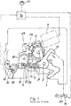
- FIG. 1 is a generic motor vehicle door lock shown in the prior art.
- a trigger lever 1 is pivotally received about an axis 2.
- the trigger lever 1 is driven by an electric motor 3 and a driven pulley 4 in the direction of the arrow, so that a locking mechanism can be unlocked.
- An actuating lever 5 is also pivotally mounted about the axis 2 axially with the trigger lever 1.
- the actuating lever 5 can be coupled to the locking lever 10 via the clutch lever 6.
- the clutch lever 6 also interacts with the child safety element 14.
- the motor vehicle door lock If the motor vehicle door lock is now locked and the childproof lock is inserted, an occupant of the motor vehicle cannot unlock the motor vehicle door lock in the closed state and thus cannot open the door.
- the motor vehicle door lock In particular, in the case in which the motor vehicle door lock has a closing drive, the motor vehicle door should be able to be opened by means of the inner door handle or the inner operating lever even during the electrical closing.
- the child lock must be designed for this. Laying out, for example, by means of a FIG. 1 not shown and temporary acting directly on the child safety element electric motor.
- the motor vehicle door lock 21 has a locking mechanism 22 consisting of pawl 23 and rotary latch 24.
- a locking sensor 25 interacts directly with the rotary latch 24.
- the position of the rotary latch 24 is queried or detected directly by means of the locking sensor 25.
- a release lever 28 can be actuated by means of an electric drive 26 and a drive disk 27. The release lever is able to unlock the locking mechanism 22.
- the motor vehicle door lock 21 can be made inoperative in such a way that the locking mechanism cannot be unlocked by means of an inner door handle 30.
- the child safety sensor 31 can be used to determine whether the child safety device 29 is inserted or not, that is, whether it is activated or deactivated.
- a closing drive acts directly on the locking mechanism 22, in particular on the rotary latch 24, and is able to transfer the locking mechanism 22 from a pre-locking position to a main locking position.
- the rotary latch 24 activates the locking sensor 25.
- a wake-up switch 33 and an opening switch 34 can be actuated by means of an actuating lever 32.
- the actuating lever 32 can be coupled to the locking lever 36 via a coupling lever 35.
- a driver 37 acts between the child safety device 29 and on the locking device 36 and the clutch lever 35.
- the switching elements 25, 31, 33, 34, 38 and 39 contained in the motor vehicle door lock 21 are connected to a control unit 40, as indicated by the dashed lines. The interaction or the integration of the switching means 25, 31, 33, 34, 38 and 39 when the inner operating lever 30 is actuated when the door is closed in cooperation with the control unit 40 is reproduced in the following flow diagrams.
- FIG. 3 shows a flow chart for opening a side door and in particular a rear side door when the inner door handle 30 and thus the actuating lever 32 are actuated.
- the opening switch 34 is actuated. If the opening switch 34 is actuated, it takes place a further query as to whether the child safety sensor 31 is activated or deactivated. If the child lock switch is activated and the child lock is thus inserted, a first query 41 is made as to whether the child lock device 29 has been temporarily switched off by means of a release switch. The vehicle driver can, for example, temporarily switch off the child safety sensor.
- the door can be opened, which can be seen in the flow diagram in the lower right box. If, after querying the child safety sensor 31, a closing process 42 takes place, the door should be able to be opened by means of the inner door handle 30.
- the child safety device 29 would therefore have to be designed mechanically.
- the mechanical design for example with an electric drive, is shown in box 43 in the flow chart.
- the door can then be opened. As an example, it should be pointed out that according to the query 42 of closing, the door cannot be opened by means of the inner door handle 30 if the closing process is not activated.
- the FIG. 3 thus shows that a mechanical drive for the child safety device 29 is required to open the door by means of the inner door handle 30 while closing.
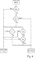
- FIG. 4 shows a method for controlling an opening of a motor vehicle door by means of an inner door handle 30 in a flowchart, in which the locking sensor 25 is integrated into the query for controlling the actuating lever 32 during the closing of the locking mechanism 22.
- the opening switch is activated first and the query is made as to whether the opening switch 34 has been actuated or not. If the opening switch 34 has been actuated, the control prompts whether the child safety sensor 31 has been activated or deactivated.
- the release switch 41 may have been operated so that the door can be opened.
- a query 42 is made as to whether the closing process is ongoing or not activated. If the closing 42 is in progress, that is to say the locking mechanism 22 is mostly electrically actuated, another takes place Querying the locking sensor 25 as to whether the locking mechanism 22 is already completely locked, that is to say that it is in the main position. If the locking mechanism 22 is not yet in the main latching position, the closing 42 still continues and the door can be opened by means of the inner door handle 30 or the actuating lever 32. According to the invention, mechanical design of the child safety device 29 can thus be dispensed with. The electrical drive for the child safety device 29 can thus be omitted.
Landscapes
- Health & Medical Sciences (AREA)
- Child & Adolescent Psychology (AREA)
- Lock And Its Accessories (AREA)
Claims (7)
- Procédé de commande d'une serrure de porte de véhicule à moteur (21), dans lequel la serrure de porte de véhicule à moteur (21) comporte• un dispositif d'encliquetage (22),• un entraînement électrique (26), dans lequel le dispositif d'encliquetage (22) est déverrouillé au moyen de l'entraînement (26),• un dispositif de sécurité pour enfants (29) doté d'un capteur de sécurité pour enfants (31), dans lequel, en fonction de la position de commutation du capteur de sécurité pour enfants (31) de l'entraînement (26), est activé ou désactivé ;• un entraînement de fermeture (42), à l'aide duquel le dispositif d'encliquetage (22) est transféré d'une position de pré-encliquetage à une position de pré-encliquetage principale, dans lequel• un capteur de dispositif d'encliquetage (25) au dispositif d'encliquetage (22) ;• le capteur de dispositif d'encliquetage (25) est activé lorsque le dispositif d'encliquetage (22) est complètement verrouillé ;• en fonction de la position de commutation du capteur de dispositif d'encliquetage (25) de l'entraînement (26) est activé ou désactivé ;• un levier d'actionnement (32) est prévu ; caractérisé en ce qu'au• moins un commutateur d'ouverture (34) est actionné au moyen du levier d'actionnement (32) ;• en ce que le commutateur d'ouverture (34) est interrogé ;• lorsque le commutateur d'ouverture (34) est activé, le capteur de sécurité pour enfants (31) est interrogé ;• lorsque le capteur de sécurité pour enfants (31) est activé, l'entraînement de fermeture (42) est interrogé ;• lorsque l'entraînement de fermeture (42) du capteur de dispositif d'encliquetage (25) est interrogé ;• lorsque le capteur de dispositif d'encliquetage (25) est désactivé, la porte est ouverte.
- Procédé selon la revendication précédente, caractérisé en ce que la position du dispositif d'encliquetage (22) est détectée en pré-encliquetage et en encliquetage principal au moyen du capteur de dispositif d'encliquetage (25).
- Procédé selon l'une quelconque des revendications précédentes, caractérisé en ce que le capteur de dispositif d'encliquetage (25) est actionné au moyen d'un loquet rotatif du dispositif d'encliquetage (22).
- Procédé selon l'une quelconque des revendications précédentes, caractérisé en ce qu'un levier d'accouplement (35) est prévu et en ce que le levier d'actionnement (32) est accouplé au levier de déclenchement (28) au moyen du levier d'accouplement (35).
- Procédé selon l'une quelconque des revendications précédentes, caractérisé en ce que le dispositif de sécurité pour enfants (29) coopère avec un levier d'enclenchement (35), dans lequel un levier intérieur d'actionnement (32) est désaccouplé au moyen du dispositif de sécurité pour enfants (29).
- Procédé selon l'une quelconque des revendications précédentes, dans lequel, si l'interrogation du capteur de sécurité pour enfants (31) indique que celui-ci n'est pas activé, la porte est ouverte.
- Procédé selon l'une quelconque des revendications précédentes, caractérisé en ce qu'une unité de commande (40) est prévue, et dans lequel, après un actionnement de la poignée intérieure de porte (30), les positions de commutation des commutateurs (25, 31, 33, 34, 38, 39) sont interrogées au moyen de l'unité de commande, et dans lesquels, et dans lequel, en fonction de la position de commutation du capteur de dispositif d'encliquetage, l'entraînement (26) est activé ou désactivé.
Applications Claiming Priority (2)
| Application Number | Priority Date | Filing Date | Title |
|---|---|---|---|
| DE102015108739.1A DE102015108739A1 (de) | 2015-06-02 | 2015-06-02 | Verfahren zur Steuerung eines Kraftfahrzeugtürverschlusses |
| PCT/DE2016/100214 WO2016192708A1 (fr) | 2015-06-02 | 2016-05-11 | Procédé de commande d'une serrure de porte de véhicule à moteur |
Publications (2)
| Publication Number | Publication Date |
|---|---|
| EP3303742A1 EP3303742A1 (fr) | 2018-04-11 |
| EP3303742B1 true EP3303742B1 (fr) | 2020-01-08 |
Family
ID=56403927
Family Applications (1)
| Application Number | Title | Priority Date | Filing Date |
|---|---|---|---|
| EP16736774.7A Active EP3303742B1 (fr) | 2015-06-02 | 2016-05-11 | Procédé de commande d'une serrure de porte de véhicule |
Country Status (7)
| Country | Link |
|---|---|
| US (1) | US11118379B2 (fr) |
| EP (1) | EP3303742B1 (fr) |
| JP (1) | JP2018516325A (fr) |
| KR (1) | KR102503613B1 (fr) |
| CN (1) | CN107849873B (fr) |
| DE (1) | DE102015108739A1 (fr) |
| WO (1) | WO2016192708A1 (fr) |
Families Citing this family (10)
| Publication number | Priority date | Publication date | Assignee | Title |
|---|---|---|---|---|
| US20180058112A1 (en) * | 2016-09-01 | 2018-03-01 | AISIN Technical Center of America, Inc. | Vehicle door closing and releasing apparatus |
| US11306518B2 (en) | 2017-03-02 | 2022-04-19 | Kiekert Ag | Vehicle door lock, especially tailgate lock |
| DE102018101575A1 (de) | 2018-01-24 | 2019-07-25 | Kiekert Ag | Schließvorrichtung für ein Kraftfahrzeug mit Crashverriegelung |
| DE102018110700A1 (de) | 2018-05-04 | 2019-11-07 | Kiekert Ag | Elektrisch betätigbares Kraftfahrzeugschloss |
| DE102018113562A1 (de) | 2018-06-07 | 2019-12-12 | Kiekert Ag | Elektrisch betätigbares Kraftfahrzeugschloss |
| KR102764299B1 (ko) * | 2019-05-14 | 2025-02-07 | 현대자동차주식회사 | 차량의 러기지룸 개폐용 래치어셈블리 |
| DE102019133654A1 (de) | 2019-12-10 | 2021-06-10 | Kiekert Aktiengesellschaft | Kraftfahrzeugschloss |
| DE102020102109A1 (de) | 2020-01-29 | 2021-07-29 | Kiekert Aktiengesellschaft | Elektrisch betätigbares Kraftfahrzeugschloss |
| US20240209658A1 (en) * | 2022-12-22 | 2024-06-27 | Brose Schließsysteme GmbH & Co. Kommanditgesellschaft | Switch configuration for motor vehicle latch |
| CN119145722A (zh) * | 2023-06-16 | 2024-12-17 | 恩坦华产品有限公司 | 车辆闩锁 |
Family Cites Families (49)
| Publication number | Priority date | Publication date | Assignee | Title |
|---|---|---|---|---|
| FR2548719B2 (fr) * | 1982-07-19 | 1986-06-06 | Cousin Cie Ets A & M Freres | Serrure electrique de securite plus specialement pour portieres de vehicules automobiles |
| JP2855557B2 (ja) * | 1993-07-30 | 1999-02-10 | 株式会社大井製作所 | 自動車用ドアロック装置 |
| DE19547727A1 (de) * | 1995-12-20 | 1997-06-26 | Vdo Schindling | Einrichtung zum Entriegeln von Türen |
| US6279361B1 (en) * | 1995-12-20 | 2001-08-28 | Vdo Adolf Schindling Ag | Lock in particular for motor vehicle doors |
| US5938252A (en) * | 1996-08-22 | 1999-08-17 | Asmo Co., Ltd. | Door member locking/unlocking apparatus |
| GB2322409B (en) | 1996-12-16 | 2001-05-23 | John Phillip Chevalier | Control system for opening a door |
| RU2194837C2 (ru) | 1997-12-12 | 2002-12-20 | Джон Филлип ШЕВАЛЬЕ | Запирающие устройства для автомобильных дверей или других запорных элементов |
| US6386599B1 (en) * | 1999-08-12 | 2002-05-14 | John Phillip Chevalier | Latch arrangement for automotive door |
| US6157090A (en) * | 1999-08-18 | 2000-12-05 | Daimlerchrysler Corporation | Electronic child safety locks |
| US6435600B1 (en) | 1999-12-21 | 2002-08-20 | Daimlerchrysler Corporation | Method for operating a vehicle power sliding door |
| JP4474740B2 (ja) * | 2000-06-15 | 2010-06-09 | アイシン精機株式会社 | 車両用ドアラッチ操作制御装置 |
| DE10038427A1 (de) * | 2000-08-07 | 2002-03-07 | Volkswagen Ag | Sicherheitseinrichtung für den Fondinsassen eines Fahrzeugs |
| JP4127457B2 (ja) | 2000-10-24 | 2008-07-30 | 三菱ふそうトラック・バス株式会社 | 車両用ドア装置 |
| GB0121066D0 (en) * | 2001-08-31 | 2001-10-24 | Meritor Light Vehicle Sys Ltd | Door latch arrangement |
| US6659515B2 (en) | 2001-10-30 | 2003-12-09 | Kiekert Ag | Power-closing motor-vehicle door latch |
| GB0130422D0 (en) * | 2001-12-20 | 2002-02-06 | Meritor Light Vehicle Sys Ltd | Vehicle |
| JP4269618B2 (ja) * | 2002-09-30 | 2009-05-27 | アイシン精機株式会社 | 車両用ドアロック装置 |
| JP2004251106A (ja) * | 2003-01-30 | 2004-09-09 | Aisin Seiki Co Ltd | ドアロック装置 |
| DE20307347U1 (de) | 2003-05-10 | 2004-09-30 | Kiekert Ag | Kraftfahrzeugtürverschluss |
| DE10336602A1 (de) * | 2003-08-08 | 2005-03-03 | Daimlerchrysler Ag | Zentralverriegelungsanlage für ein Kraftfahrzeug mit einer elektronischen Steuereinheit |
| US7441815B2 (en) * | 2003-12-25 | 2008-10-28 | Mitsui Mining & Smelting Co., Ltd. | Door lock device |
| GB0612879D0 (en) * | 2006-06-29 | 2006-08-09 | Meritor Technology Inc | Electrical circuit arrangement |
| JP4734212B2 (ja) * | 2006-10-17 | 2011-07-27 | 三井金属アクト株式会社 | ラッチ装置 |
| JP4795195B2 (ja) * | 2006-10-17 | 2011-10-19 | 三井金属アクト株式会社 | ラッチ装置 |
| GB2451820B (en) * | 2007-08-11 | 2012-05-16 | Body Systems Usa Llc | Vehicle door latch system |
| DE202007016719U1 (de) * | 2007-11-28 | 2009-04-02 | Kiekert Ag | Kraftfahrzeugtürverschluss |
| EP2071106B1 (fr) * | 2007-12-14 | 2015-10-28 | Volvo Car Corporation | Dispositif de fixation à fermeture motorisée |
| DE102008009506A1 (de) * | 2008-02-15 | 2009-08-20 | Kiekert Ag | Kraftfahrzeugtürverschluss |
| JP4618318B2 (ja) * | 2008-04-18 | 2011-01-26 | アイシン精機株式会社 | 車両用ドアロック装置 |
| JP5332458B2 (ja) * | 2008-09-29 | 2013-11-06 | アイシン精機株式会社 | ドアロック装置 |
| JP5110390B2 (ja) * | 2008-11-18 | 2012-12-26 | アイシン精機株式会社 | 開閉体制御装置 |
| US8474888B2 (en) * | 2009-03-25 | 2013-07-02 | Magna Closures Inc. | Closure latch for vehicle door |
| DE102009037037B4 (de) * | 2009-08-13 | 2018-10-18 | BÖCO Böddecker & Co. GmbH & Co. KG | Verriegelungsvorrichtung für eine Fahrzeugtür |
| GB2474846A (en) * | 2009-10-27 | 2011-05-04 | Arvinmeritor Light Vehicle Sys | Latch system comprising key barrel operably coupled to latch via a clutch mechanism |
| DE202010009333U1 (de) | 2010-06-21 | 2011-10-20 | BROSE SCHLIEßSYSTEME GMBH & CO. KG | Kraftfahrzeugschloss |
| JP5718147B2 (ja) * | 2011-05-16 | 2015-05-13 | 三井金属鉱業株式会社 | 車両用ドアラッチシステム |
| DE102012003743A1 (de) | 2012-02-28 | 2013-08-29 | Kiekert Aktiengesellschaft | Kraftfahrzeugtürverschluss |
| DE202012003171U1 (de) | 2012-03-28 | 2013-07-01 | Kiekert Aktiengesellschaft | Kraftfahrzeugtürverschluss |
| US9145716B2 (en) * | 2012-05-09 | 2015-09-29 | Ford Global Technologies, Llc | Deployable hood latch for pedestrian head protection |
| KR101896711B1 (ko) * | 2012-09-17 | 2018-09-07 | 현대자동차주식회사 | 능동형 도어락 시스템 |
| US9644403B2 (en) * | 2012-10-18 | 2017-05-09 | GM Global Technology Operations LLC | System for controlling locking module for vehicle door |
| DE102012020424A1 (de) * | 2012-10-18 | 2014-02-20 | Kiekert Aktiengesellschaft | Kraftfahrzeugtürschloss |
| DE102012111288A1 (de) * | 2012-11-22 | 2014-05-22 | Kiekert Aktiengesellschaft | Kraftfahrzeugtürverschluss |
| CN203285188U (zh) * | 2013-05-21 | 2013-11-13 | 河南北方星光机电有限责任公司 | 一种汽车门锁的远程电动拖入机构 |
| DE102013014038A1 (de) * | 2013-08-22 | 2015-02-26 | Kiekert Aktiengesellschaft | Kraftfahrzeugtürverschluss |
| EP2843168B1 (fr) * | 2013-09-02 | 2018-11-28 | Witte Automotive GmbH | Serrure de véhicule automobile |
| FR3014472B1 (fr) * | 2013-12-10 | 2017-10-06 | Inteva Products Llc | Ensemble et systeme de verrouillage de portiere |
| CN104358481A (zh) * | 2014-09-10 | 2015-02-18 | 安徽江淮汽车股份有限公司 | 滑门锁控制转换机构和滑门锁 |
| DE102015108738A1 (de) | 2015-06-02 | 2016-12-08 | Kiekert Ag | Kraftfahrzeugtürverschluss |
-
2015
- 2015-06-02 DE DE102015108739.1A patent/DE102015108739A1/de not_active Withdrawn
-
2016
- 2016-05-11 US US15/578,971 patent/US11118379B2/en active Active
- 2016-05-11 CN CN201680045346.0A patent/CN107849873B/zh active Active
- 2016-05-11 JP JP2017562986A patent/JP2018516325A/ja active Pending
- 2016-05-11 EP EP16736774.7A patent/EP3303742B1/fr active Active
- 2016-05-11 KR KR1020177037848A patent/KR102503613B1/ko active Active
- 2016-05-11 WO PCT/DE2016/100214 patent/WO2016192708A1/fr not_active Ceased
Non-Patent Citations (1)
| Title |
|---|
| None * |
Also Published As
| Publication number | Publication date |
|---|---|
| EP3303742A1 (fr) | 2018-04-11 |
| CN107849873B (zh) | 2019-07-30 |
| CN107849873A (zh) | 2018-03-27 |
| KR20180014783A (ko) | 2018-02-09 |
| WO2016192708A1 (fr) | 2016-12-08 |
| US20180135338A1 (en) | 2018-05-17 |
| KR102503613B1 (ko) | 2023-02-24 |
| US11118379B2 (en) | 2021-09-14 |
| DE102015108739A1 (de) | 2016-12-08 |
| JP2018516325A (ja) | 2018-06-21 |
Similar Documents
| Publication | Publication Date | Title |
|---|---|---|
| EP3303742B1 (fr) | Procédé de commande d'une serrure de porte de véhicule | |
| EP3303741B1 (fr) | Serrure de porte de véhicule | |
| DE19635414C2 (de) | Schloß, insbesondere für Fahrzeugtüren oder dergleichen | |
| EP2831356B1 (fr) | Serrure de porte de véhicule automobile | |
| EP3942138B1 (fr) | Dispositif d'ouverture pour un élément de porte de véhicule à moteur | |
| EP1922464B1 (fr) | Vehicule automobile et serrure de portiere pour une portiere d'un vehicule automobile | |
| EP3390748B1 (fr) | Verrou de véhicule automobile | |
| DE102016210251A1 (de) | Schließzylinder-Freigabemechanismus für Fahrzeugschließverriegelungen, Verriegelungsanordnung damit und Verfahren zum mechanischen Freigeben einer Fahrzeugschließverriegelung | |
| DE19619849A1 (de) | Schloß, insbesondere für Kraftfahrzeugtüren | |
| DE102019105729A1 (de) | Klappe für ein griffloses Verschlusspaneel in Kraftfahrzeugen | |
| DE102018110700A1 (de) | Elektrisch betätigbares Kraftfahrzeugschloss | |
| DE102008048773A1 (de) | Kraftfahrzeugtürverschluss | |
| DE102017101704A1 (de) | Schloss mit Zuzieheinrichtung für ein Kraftfahrzeug | |
| WO2018137738A1 (fr) | Serrure de véhicule automobile munie d'un dispositif de fermeture | |
| WO2014169889A1 (fr) | Système de verrouillage de porte de véhicule à moteur | |
| WO2018006896A1 (fr) | Serrure de véhicule automobile | |
| EP4263983A1 (fr) | Verrou de véhicule automobile | |
| DE19924458B4 (de) | Kraftfahrzeug-Türschließeinrichtung | |
| EP4214391A1 (fr) | Appareil d'ouverture destiné à un élément de portière de véhicule automobile | |
| DE102020108753A1 (de) | Verfahren zum Betrieb eines Kraftfahrzeugschließsystem | |
| WO2023030576A1 (fr) | Serrure de véhicule automobile | |
| DE19955936A1 (de) | Kraftfahrzeugschlüssel mit Fernbedienung | |
| DE29921946U1 (de) | Schaltvorrichtung für einen Diebstahlsicherungsantrieb eines Kraftfahrzeugtürverschlusses | |
| DE102019001951A1 (de) | Türschlosseinrichtung für die Fondtür eines Kraftfahrzeugs | |
| WO2019063040A1 (fr) | Serrure de véhicule à moteur |
Legal Events
| Date | Code | Title | Description |
|---|---|---|---|
| STAA | Information on the status of an ep patent application or granted ep patent |
Free format text: STATUS: THE INTERNATIONAL PUBLICATION HAS BEEN MADE |
|
| PUAI | Public reference made under article 153(3) epc to a published international application that has entered the european phase |
Free format text: ORIGINAL CODE: 0009012 |
|
| STAA | Information on the status of an ep patent application or granted ep patent |
Free format text: STATUS: REQUEST FOR EXAMINATION WAS MADE |
|
| 17P | Request for examination filed |
Effective date: 20171207 |
|
| AK | Designated contracting states |
Kind code of ref document: A1 Designated state(s): AL AT BE BG CH CY CZ DE DK EE ES FI FR GB GR HR HU IE IS IT LI LT LU LV MC MK MT NL NO PL PT RO RS SE SI SK SM TR |
|
| AX | Request for extension of the european patent |
Extension state: BA ME |
|
| DAV | Request for validation of the european patent (deleted) | ||
| DAX | Request for extension of the european patent (deleted) | ||
| GRAP | Despatch of communication of intention to grant a patent |
Free format text: ORIGINAL CODE: EPIDOSNIGR1 |
|
| STAA | Information on the status of an ep patent application or granted ep patent |
Free format text: STATUS: GRANT OF PATENT IS INTENDED |
|
| INTG | Intention to grant announced |
Effective date: 20191015 |
|
| GRAS | Grant fee paid |
Free format text: ORIGINAL CODE: EPIDOSNIGR3 |
|
| GRAA | (expected) grant |
Free format text: ORIGINAL CODE: 0009210 |
|
| STAA | Information on the status of an ep patent application or granted ep patent |
Free format text: STATUS: THE PATENT HAS BEEN GRANTED |
|
| AK | Designated contracting states |
Kind code of ref document: B1 Designated state(s): AL AT BE BG CH CY CZ DE DK EE ES FI FR GB GR HR HU IE IS IT LI LT LU LV MC MK MT NL NO PL PT RO RS SE SI SK SM TR |
|
| REG | Reference to a national code |
Ref country code: GB Ref legal event code: FG4D Free format text: NOT ENGLISH |
|
| REG | Reference to a national code |
Ref country code: CH Ref legal event code: EP |
|
| REG | Reference to a national code |
Ref country code: DE Ref legal event code: R096 Ref document number: 502016008351 Country of ref document: DE |
|
| REG | Reference to a national code |
Ref country code: IE Ref legal event code: FG4D Free format text: LANGUAGE OF EP DOCUMENT: GERMAN |
|
| REG | Reference to a national code |
Ref country code: AT Ref legal event code: REF Ref document number: 1222906 Country of ref document: AT Kind code of ref document: T Effective date: 20200215 |
|
| REG | Reference to a national code |
Ref country code: NL Ref legal event code: MP Effective date: 20200108 |
|
| REG | Reference to a national code |
Ref country code: LT Ref legal event code: MG4D |
|
| PG25 | Lapsed in a contracting state [announced via postgrant information from national office to epo] |
Ref country code: NL Free format text: LAPSE BECAUSE OF FAILURE TO SUBMIT A TRANSLATION OF THE DESCRIPTION OR TO PAY THE FEE WITHIN THE PRESCRIBED TIME-LIMIT Effective date: 20200108 Ref country code: RS Free format text: LAPSE BECAUSE OF FAILURE TO SUBMIT A TRANSLATION OF THE DESCRIPTION OR TO PAY THE FEE WITHIN THE PRESCRIBED TIME-LIMIT Effective date: 20200108 Ref country code: LT Free format text: LAPSE BECAUSE OF FAILURE TO SUBMIT A TRANSLATION OF THE DESCRIPTION OR TO PAY THE FEE WITHIN THE PRESCRIBED TIME-LIMIT Effective date: 20200108 Ref country code: PT Free format text: LAPSE BECAUSE OF FAILURE TO SUBMIT A TRANSLATION OF THE DESCRIPTION OR TO PAY THE FEE WITHIN THE PRESCRIBED TIME-LIMIT Effective date: 20200531 Ref country code: NO Free format text: LAPSE BECAUSE OF FAILURE TO SUBMIT A TRANSLATION OF THE DESCRIPTION OR TO PAY THE FEE WITHIN THE PRESCRIBED TIME-LIMIT Effective date: 20200408 Ref country code: FI Free format text: LAPSE BECAUSE OF FAILURE TO SUBMIT A TRANSLATION OF THE DESCRIPTION OR TO PAY THE FEE WITHIN THE PRESCRIBED TIME-LIMIT Effective date: 20200108 |
|
| PG25 | Lapsed in a contracting state [announced via postgrant information from national office to epo] |
Ref country code: LV Free format text: LAPSE BECAUSE OF FAILURE TO SUBMIT A TRANSLATION OF THE DESCRIPTION OR TO PAY THE FEE WITHIN THE PRESCRIBED TIME-LIMIT Effective date: 20200108 Ref country code: SE Free format text: LAPSE BECAUSE OF FAILURE TO SUBMIT A TRANSLATION OF THE DESCRIPTION OR TO PAY THE FEE WITHIN THE PRESCRIBED TIME-LIMIT Effective date: 20200108 Ref country code: HR Free format text: LAPSE BECAUSE OF FAILURE TO SUBMIT A TRANSLATION OF THE DESCRIPTION OR TO PAY THE FEE WITHIN THE PRESCRIBED TIME-LIMIT Effective date: 20200108 Ref country code: BG Free format text: LAPSE BECAUSE OF FAILURE TO SUBMIT A TRANSLATION OF THE DESCRIPTION OR TO PAY THE FEE WITHIN THE PRESCRIBED TIME-LIMIT Effective date: 20200408 Ref country code: IS Free format text: LAPSE BECAUSE OF FAILURE TO SUBMIT A TRANSLATION OF THE DESCRIPTION OR TO PAY THE FEE WITHIN THE PRESCRIBED TIME-LIMIT Effective date: 20200508 Ref country code: GR Free format text: LAPSE BECAUSE OF FAILURE TO SUBMIT A TRANSLATION OF THE DESCRIPTION OR TO PAY THE FEE WITHIN THE PRESCRIBED TIME-LIMIT Effective date: 20200409 |
|
| REG | Reference to a national code |
Ref country code: DE Ref legal event code: R097 Ref document number: 502016008351 Country of ref document: DE |
|
| PG25 | Lapsed in a contracting state [announced via postgrant information from national office to epo] |
Ref country code: SK Free format text: LAPSE BECAUSE OF FAILURE TO SUBMIT A TRANSLATION OF THE DESCRIPTION OR TO PAY THE FEE WITHIN THE PRESCRIBED TIME-LIMIT Effective date: 20200108 Ref country code: RO Free format text: LAPSE BECAUSE OF FAILURE TO SUBMIT A TRANSLATION OF THE DESCRIPTION OR TO PAY THE FEE WITHIN THE PRESCRIBED TIME-LIMIT Effective date: 20200108 Ref country code: EE Free format text: LAPSE BECAUSE OF FAILURE TO SUBMIT A TRANSLATION OF THE DESCRIPTION OR TO PAY THE FEE WITHIN THE PRESCRIBED TIME-LIMIT Effective date: 20200108 Ref country code: SM Free format text: LAPSE BECAUSE OF FAILURE TO SUBMIT A TRANSLATION OF THE DESCRIPTION OR TO PAY THE FEE WITHIN THE PRESCRIBED TIME-LIMIT Effective date: 20200108 Ref country code: DK Free format text: LAPSE BECAUSE OF FAILURE TO SUBMIT A TRANSLATION OF THE DESCRIPTION OR TO PAY THE FEE WITHIN THE PRESCRIBED TIME-LIMIT Effective date: 20200108 Ref country code: ES Free format text: LAPSE BECAUSE OF FAILURE TO SUBMIT A TRANSLATION OF THE DESCRIPTION OR TO PAY THE FEE WITHIN THE PRESCRIBED TIME-LIMIT Effective date: 20200108 |
|
| PLBE | No opposition filed within time limit |
Free format text: ORIGINAL CODE: 0009261 |
|
| STAA | Information on the status of an ep patent application or granted ep patent |
Free format text: STATUS: NO OPPOSITION FILED WITHIN TIME LIMIT |
|
| 26N | No opposition filed |
Effective date: 20201009 |
|
| PG25 | Lapsed in a contracting state [announced via postgrant information from national office to epo] |
Ref country code: CH Free format text: LAPSE BECAUSE OF NON-PAYMENT OF DUE FEES Effective date: 20200531 Ref country code: IT Free format text: LAPSE BECAUSE OF FAILURE TO SUBMIT A TRANSLATION OF THE DESCRIPTION OR TO PAY THE FEE WITHIN THE PRESCRIBED TIME-LIMIT Effective date: 20200108 Ref country code: LI Free format text: LAPSE BECAUSE OF NON-PAYMENT OF DUE FEES Effective date: 20200531 Ref country code: MC Free format text: LAPSE BECAUSE OF FAILURE TO SUBMIT A TRANSLATION OF THE DESCRIPTION OR TO PAY THE FEE WITHIN THE PRESCRIBED TIME-LIMIT Effective date: 20200108 |
|
| PG25 | Lapsed in a contracting state [announced via postgrant information from national office to epo] |
Ref country code: PL Free format text: LAPSE BECAUSE OF FAILURE TO SUBMIT A TRANSLATION OF THE DESCRIPTION OR TO PAY THE FEE WITHIN THE PRESCRIBED TIME-LIMIT Effective date: 20200108 Ref country code: SI Free format text: LAPSE BECAUSE OF FAILURE TO SUBMIT A TRANSLATION OF THE DESCRIPTION OR TO PAY THE FEE WITHIN THE PRESCRIBED TIME-LIMIT Effective date: 20200108 |
|
| REG | Reference to a national code |
Ref country code: BE Ref legal event code: MM Effective date: 20200531 |
|
| GBPC | Gb: european patent ceased through non-payment of renewal fee |
Effective date: 20200511 |
|
| PG25 | Lapsed in a contracting state [announced via postgrant information from national office to epo] |
Ref country code: LU Free format text: LAPSE BECAUSE OF NON-PAYMENT OF DUE FEES Effective date: 20200511 |
|
| PG25 | Lapsed in a contracting state [announced via postgrant information from national office to epo] |
Ref country code: GB Free format text: LAPSE BECAUSE OF NON-PAYMENT OF DUE FEES Effective date: 20200511 Ref country code: IE Free format text: LAPSE BECAUSE OF NON-PAYMENT OF DUE FEES Effective date: 20200511 |
|
| PG25 | Lapsed in a contracting state [announced via postgrant information from national office to epo] |
Ref country code: BE Free format text: LAPSE BECAUSE OF NON-PAYMENT OF DUE FEES Effective date: 20200531 |
|
| PG25 | Lapsed in a contracting state [announced via postgrant information from national office to epo] |
Ref country code: TR Free format text: LAPSE BECAUSE OF FAILURE TO SUBMIT A TRANSLATION OF THE DESCRIPTION OR TO PAY THE FEE WITHIN THE PRESCRIBED TIME-LIMIT Effective date: 20200108 Ref country code: MT Free format text: LAPSE BECAUSE OF FAILURE TO SUBMIT A TRANSLATION OF THE DESCRIPTION OR TO PAY THE FEE WITHIN THE PRESCRIBED TIME-LIMIT Effective date: 20200108 Ref country code: CY Free format text: LAPSE BECAUSE OF FAILURE TO SUBMIT A TRANSLATION OF THE DESCRIPTION OR TO PAY THE FEE WITHIN THE PRESCRIBED TIME-LIMIT Effective date: 20200108 |
|
| PG25 | Lapsed in a contracting state [announced via postgrant information from national office to epo] |
Ref country code: MK Free format text: LAPSE BECAUSE OF FAILURE TO SUBMIT A TRANSLATION OF THE DESCRIPTION OR TO PAY THE FEE WITHIN THE PRESCRIBED TIME-LIMIT Effective date: 20200108 Ref country code: AL Free format text: LAPSE BECAUSE OF FAILURE TO SUBMIT A TRANSLATION OF THE DESCRIPTION OR TO PAY THE FEE WITHIN THE PRESCRIBED TIME-LIMIT Effective date: 20200108 |
|
| REG | Reference to a national code |
Ref country code: AT Ref legal event code: MM01 Ref document number: 1222906 Country of ref document: AT Kind code of ref document: T Effective date: 20210511 |
|
| PG25 | Lapsed in a contracting state [announced via postgrant information from national office to epo] |
Ref country code: AT Free format text: LAPSE BECAUSE OF NON-PAYMENT OF DUE FEES Effective date: 20210511 |
|
| P01 | Opt-out of the competence of the unified patent court (upc) registered |
Effective date: 20230529 |
|
| PGFP | Annual fee paid to national office [announced via postgrant information from national office to epo] |
Ref country code: DE Payment date: 20250519 Year of fee payment: 10 |
|
| PGFP | Annual fee paid to national office [announced via postgrant information from national office to epo] |
Ref country code: FR Payment date: 20250521 Year of fee payment: 10 |
|
| PGFP | Annual fee paid to national office [announced via postgrant information from national office to epo] |
Ref country code: CZ Payment date: 20250428 Year of fee payment: 10 |