EP3303792B1 - Abgasdruckregler für einen verbrennungsmotor - Google Patents
Abgasdruckregler für einen verbrennungsmotor Download PDFInfo
- Publication number
- EP3303792B1 EP3303792B1 EP15727349.1A EP15727349A EP3303792B1 EP 3303792 B1 EP3303792 B1 EP 3303792B1 EP 15727349 A EP15727349 A EP 15727349A EP 3303792 B1 EP3303792 B1 EP 3303792B1
- Authority
- EP
- European Patent Office
- Prior art keywords
- exhaust gas
- gas pressure
- regulator
- pressure regulator
- diffuser assembly
- Prior art date
- Legal status (The legal status is an assumption and is not a legal conclusion. Google has not performed a legal analysis and makes no representation as to the accuracy of the status listed.)
- Active
Links
Images


Classifications
-
- F—MECHANICAL ENGINEERING; LIGHTING; HEATING; WEAPONS; BLASTING
- F02—COMBUSTION ENGINES; HOT-GAS OR COMBUSTION-PRODUCT ENGINE PLANTS
- F02B—INTERNAL-COMBUSTION PISTON ENGINES; COMBUSTION ENGINES IN GENERAL
- F02B37/00—Engines characterised by provision of pumps driven at least for part of the time by exhaust
- F02B37/12—Control of the pumps
- F02B37/24—Control of the pumps by using pumps or turbines with adjustable guide vanes
-
- F—MECHANICAL ENGINEERING; LIGHTING; HEATING; WEAPONS; BLASTING
- F01—MACHINES OR ENGINES IN GENERAL; ENGINE PLANTS IN GENERAL; STEAM ENGINES
- F01N—GAS-FLOW SILENCERS OR EXHAUST APPARATUS FOR MACHINES OR ENGINES IN GENERAL; GAS-FLOW SILENCERS OR EXHAUST APPARATUS FOR INTERNAL-COMBUSTION ENGINES
- F01N13/00—Exhaust or silencing apparatus characterised by constructional features
- F01N13/08—Other arrangements or adaptations of exhaust conduits
-
- F—MECHANICAL ENGINEERING; LIGHTING; HEATING; WEAPONS; BLASTING
- F02—COMBUSTION ENGINES; HOT-GAS OR COMBUSTION-PRODUCT ENGINE PLANTS
- F02B—INTERNAL-COMBUSTION PISTON ENGINES; COMBUSTION ENGINES IN GENERAL
- F02B37/00—Engines characterised by provision of pumps driven at least for part of the time by exhaust
- F02B37/004—Engines characterised by provision of pumps driven at least for part of the time by exhaust with exhaust drives arranged in series
-
- F—MECHANICAL ENGINEERING; LIGHTING; HEATING; WEAPONS; BLASTING
- F02—COMBUSTION ENGINES; HOT-GAS OR COMBUSTION-PRODUCT ENGINE PLANTS
- F02B—INTERNAL-COMBUSTION PISTON ENGINES; COMBUSTION ENGINES IN GENERAL
- F02B37/00—Engines characterised by provision of pumps driven at least for part of the time by exhaust
- F02B37/005—Exhaust driven pumps being combined with an exhaust driven auxiliary apparatus, e.g. a ventilator
-
- F—MECHANICAL ENGINEERING; LIGHTING; HEATING; WEAPONS; BLASTING
- F02—COMBUSTION ENGINES; HOT-GAS OR COMBUSTION-PRODUCT ENGINE PLANTS
- F02B—INTERNAL-COMBUSTION PISTON ENGINES; COMBUSTION ENGINES IN GENERAL
- F02B37/00—Engines characterised by provision of pumps driven at least for part of the time by exhaust
- F02B37/013—Engines characterised by provision of pumps driven at least for part of the time by exhaust with exhaust-driven pumps arranged in series
-
- F—MECHANICAL ENGINEERING; LIGHTING; HEATING; WEAPONS; BLASTING
- F02—COMBUSTION ENGINES; HOT-GAS OR COMBUSTION-PRODUCT ENGINE PLANTS
- F02B—INTERNAL-COMBUSTION PISTON ENGINES; COMBUSTION ENGINES IN GENERAL
- F02B37/00—Engines characterised by provision of pumps driven at least for part of the time by exhaust
- F02B37/12—Control of the pumps
- F02B37/18—Control of the pumps by bypassing exhaust from the inlet to the outlet of turbine or to the atmosphere
- F02B37/183—Arrangements of bypass valves or actuators therefor
-
- F—MECHANICAL ENGINEERING; LIGHTING; HEATING; WEAPONS; BLASTING
- F02—COMBUSTION ENGINES; HOT-GAS OR COMBUSTION-PRODUCT ENGINE PLANTS
- F02B—INTERNAL-COMBUSTION PISTON ENGINES; COMBUSTION ENGINES IN GENERAL
- F02B37/00—Engines characterised by provision of pumps driven at least for part of the time by exhaust
- F02B37/12—Control of the pumps
- F02B37/22—Control of the pumps by varying cross-section of exhaust passages or air passages, e.g. by throttling turbine inlets or outlets or by varying effective number of guide conduits
-
- F—MECHANICAL ENGINEERING; LIGHTING; HEATING; WEAPONS; BLASTING
- F02—COMBUSTION ENGINES; HOT-GAS OR COMBUSTION-PRODUCT ENGINE PLANTS
- F02B—INTERNAL-COMBUSTION PISTON ENGINES; COMBUSTION ENGINES IN GENERAL
- F02B41/00—Engines characterised by special means for improving conversion of heat or pressure energy into mechanical power
- F02B41/02—Engines with prolonged expansion
- F02B41/10—Engines with prolonged expansion in exhaust turbines
-
- F—MECHANICAL ENGINEERING; LIGHTING; HEATING; WEAPONS; BLASTING
- F01—MACHINES OR ENGINES IN GENERAL; ENGINE PLANTS IN GENERAL; STEAM ENGINES
- F01N—GAS-FLOW SILENCERS OR EXHAUST APPARATUS FOR MACHINES OR ENGINES IN GENERAL; GAS-FLOW SILENCERS OR EXHAUST APPARATUS FOR INTERNAL-COMBUSTION ENGINES
- F01N2260/00—Exhaust treating devices having provisions not otherwise provided for
- F01N2260/14—Exhaust treating devices having provisions not otherwise provided for for modifying or adapting flow area or back-pressure
-
- F—MECHANICAL ENGINEERING; LIGHTING; HEATING; WEAPONS; BLASTING
- F01—MACHINES OR ENGINES IN GENERAL; ENGINE PLANTS IN GENERAL; STEAM ENGINES
- F01N—GAS-FLOW SILENCERS OR EXHAUST APPARATUS FOR MACHINES OR ENGINES IN GENERAL; GAS-FLOW SILENCERS OR EXHAUST APPARATUS FOR INTERNAL-COMBUSTION ENGINES
- F01N2260/00—Exhaust treating devices having provisions not otherwise provided for
- F01N2260/16—Exhaust treating devices having provisions not otherwise provided for for reducing exhaust flow pulsations
-
- F—MECHANICAL ENGINEERING; LIGHTING; HEATING; WEAPONS; BLASTING
- F01—MACHINES OR ENGINES IN GENERAL; ENGINE PLANTS IN GENERAL; STEAM ENGINES
- F01N—GAS-FLOW SILENCERS OR EXHAUST APPARATUS FOR MACHINES OR ENGINES IN GENERAL; GAS-FLOW SILENCERS OR EXHAUST APPARATUS FOR INTERNAL-COMBUSTION ENGINES
- F01N2340/00—Dimensional characteristics of the exhaust system, e.g. length, diameter or volume of the exhaust apparatus; Spatial arrangements of exhaust apparatuses
-
- F—MECHANICAL ENGINEERING; LIGHTING; HEATING; WEAPONS; BLASTING
- F01—MACHINES OR ENGINES IN GENERAL; ENGINE PLANTS IN GENERAL; STEAM ENGINES
- F01N—GAS-FLOW SILENCERS OR EXHAUST APPARATUS FOR MACHINES OR ENGINES IN GENERAL; GAS-FLOW SILENCERS OR EXHAUST APPARATUS FOR INTERNAL-COMBUSTION ENGINES
- F01N2470/00—Structure or shape of exhaust gas passages, pipes or tubes
- F01N2470/08—Exhaust gas passages being formed between the walls of an outer shell and an inner chamber
-
- F—MECHANICAL ENGINEERING; LIGHTING; HEATING; WEAPONS; BLASTING
- F01—MACHINES OR ENGINES IN GENERAL; ENGINE PLANTS IN GENERAL; STEAM ENGINES
- F01N—GAS-FLOW SILENCERS OR EXHAUST APPARATUS FOR MACHINES OR ENGINES IN GENERAL; GAS-FLOW SILENCERS OR EXHAUST APPARATUS FOR INTERNAL-COMBUSTION ENGINES
- F01N2470/00—Structure or shape of exhaust gas passages, pipes or tubes
- F01N2470/20—Dimensional characteristics of tubes, e.g. length, diameter
-
- F—MECHANICAL ENGINEERING; LIGHTING; HEATING; WEAPONS; BLASTING
- F01—MACHINES OR ENGINES IN GENERAL; ENGINE PLANTS IN GENERAL; STEAM ENGINES
- F01N—GAS-FLOW SILENCERS OR EXHAUST APPARATUS FOR MACHINES OR ENGINES IN GENERAL; GAS-FLOW SILENCERS OR EXHAUST APPARATUS FOR INTERNAL-COMBUSTION ENGINES
- F01N2470/00—Structure or shape of exhaust gas passages, pipes or tubes
- F01N2470/30—Tubes with restrictions, i.e. venturi or the like, e.g. for sucking air or measuring mass flow
-
- F—MECHANICAL ENGINEERING; LIGHTING; HEATING; WEAPONS; BLASTING
- F02—COMBUSTION ENGINES; HOT-GAS OR COMBUSTION-PRODUCT ENGINE PLANTS
- F02D—CONTROLLING COMBUSTION ENGINES
- F02D9/00—Controlling engines by throttling air or fuel-and-air induction conduits or exhaust conduits
- F02D9/04—Controlling engines by throttling air or fuel-and-air induction conduits or exhaust conduits concerning exhaust conduits
- F02D9/06—Exhaust brakes
-
- F—MECHANICAL ENGINEERING; LIGHTING; HEATING; WEAPONS; BLASTING
- F02—COMBUSTION ENGINES; HOT-GAS OR COMBUSTION-PRODUCT ENGINE PLANTS
- F02D—CONTROLLING COMBUSTION ENGINES
- F02D9/00—Controlling engines by throttling air or fuel-and-air induction conduits or exhaust conduits
- F02D9/08—Throttle valves specially adapted therefor; Arrangements of such valves in conduits
- F02D9/12—Throttle valves specially adapted therefor; Arrangements of such valves in conduits having slidably-mounted valve members; having valve members movable longitudinally of conduit
-
- Y—GENERAL TAGGING OF NEW TECHNOLOGICAL DEVELOPMENTS; GENERAL TAGGING OF CROSS-SECTIONAL TECHNOLOGIES SPANNING OVER SEVERAL SECTIONS OF THE IPC; TECHNICAL SUBJECTS COVERED BY FORMER USPC CROSS-REFERENCE ART COLLECTIONS [XRACs] AND DIGESTS
- Y02—TECHNOLOGIES OR APPLICATIONS FOR MITIGATION OR ADAPTATION AGAINST CLIMATE CHANGE
- Y02T—CLIMATE CHANGE MITIGATION TECHNOLOGIES RELATED TO TRANSPORTATION
- Y02T10/00—Road transport of goods or passengers
- Y02T10/10—Internal combustion engine [ICE] based vehicles
- Y02T10/12—Improving ICE efficiencies
Definitions
- the present invention relates to an exhaust gas pressure regulator for an engine. More particularly, the present invention relates to an exhaust gas pressure regulator having a moveable regulating member for controlling the exhaust gas through flow. Exhaust gas pressure regulators may be used for controlling a back-pressure in the exhaust system, thereby enabling controlled engine braking.
- the exhaust gas pressure regulator of the invention can be implemented in the exhaust system for combustion engines configured to be installed in for example heavy-duty vehicles, such as trucks, buses, working machines and construction equipment, but also other types of vehicles, such automobiles.
- Combustion engines in particular piston engines, may be provided with an exhaust gas pressure regulator for allowing exhaust brake functionality.
- an exhaust gas pressure regulator for allowing exhaust brake functionality.
- the exhaust gas pressure upstream the exhaust gas pressure regulator will increase.
- the high-pressure exhaust gas within the exhaust system will generate a relatively large counter force on the top side of the pistons during the exhaust stroke of the piston, such that the combustion engine is forced to slow down.
- US2009217662 describes an example of an exhaust gas pressure regulator having a moveable piston arranged in a diffuser duct for controlling the back-pressure in the exhaust system upstream of the regulator.
- a regulating pressure source will be connected to an inner piston chamber for forcing a control piston towards its closed position.
- a built up pressure on a regulator inlet end will result in increased gas pressure upstream the piston.
- the pressure will more or less simultaneously increase also inside a chamber formed inside the cone due to the pressure equalising channel 50.
- the pressure increase will thus act on the piston and cause the piston to move back towards its open position.
- increased gas flow past the piston will occur, such that the pressure on the regulator inlet end will drop.
- a regulating pressure of the exhaust gas pressure regulator again will force the control piston towards its closed position.
- an object of the invention is to provide an improved exhaust gas pressure regulator in terms of reliability and reduced risk for damages.
- the exhaust gas pressure regulator is suitable for a combustion engine and comprises a regulator housing and an inner diffuser assembly arranged inside the regulator housing so that an exhaust gas flow duct is formed between an inner surface of the regulator housing and an outer surface of the inner diffuser assembly.
- the inner diffuser assembly includes a front portion and a regulating piston that is moveable relative to the front portion and the regulator housing between an idle position in which the exhaust gas flow duct is open, and a pressurized position in which the regulating piston at least partly closes the exhaust gas flow duct.
- the inner diffuser assembly comprises at least one throttled flow passage between the gas flow duct and an exhaust gas pressure chamber defined by the regulating piston and an interior surface of the front portion.
- This set of features ensures that the pressure within the exhaust gas pressure chamber does not oscillate with the same amplitude as the pressure within the gas flow duct. Since part of the effective surface area of the regulating piston accessible by exhaust gas for exerting an axial force on the regulating piston towards the outlet of the regulating housing does no longer experience the high amplitude oscillations, i.e. the part of the regulating piston defining the exhaust gas pressure chamber, the amount of effective surface area of the regulating piston accessible by high amplitude oscillating exhaust gas for exerting an axial force on the regulating piston towards the outlet of the regulating housing is reduced.
- the regulating piston effective surface area which is affected by the large pressure oscillations is decreased, and since the axial force exerted on the regulating is proportional to the effective surface area, the oscillating force on the regulating piston is reduced. Thereby, there is less risk for high amplitude oscillations of the regulating piston, and consequently also less risk for damages to the regulating piston, the housing, the spring or and damper element.
- the at least one throttled flow passage is configured to form a low-pass filter for stopping high-frequency pressure pulses from reaching the regulating piston 130, but allowing pass of low-frequency pressure pulsations.
- the low-pass filter enables the average pressure within the exhaust gas pressure chamber 132 to follow the average pressure of the exhaust gas within any of the exhaust gas duct 106.
- the front portion is stationary arranged in the regulator housing.
- a stationery front portion with an internally arranged regulating valve enables less effective surface area accessible by the high amplitude pressure oscillations in the exhaust gas stream, such that the regulating piston will less likely be damaged due to osculating impacts against the regulating housing at the end positions.
- the at least one throttled flow passage is configured such that an average pressure level within the exhaust gas pressure chamber corresponds substantially to an average exhaust gas pressure level of the exhaust gas stream at an inlet to the throttled flow passage.
- a total throttled flow passage of the diffuser assembly has a flow area in the range of 0.5 - 10 mm 2 , specifically in the range of 1 - 6 mm 2 , more specifically in the range of 2 - 4 mm 2 . These ranges are deemed appropriate for enabling a balance between risk for regulator damages and delay of engine brake performance at transient conditions.
- the total throttled flow passage is configured such that a degree of pressure attenuation of the high frequency components of the dynamic pressure pulsations in the exhaust gas flow duct is at least -6 dB, specifically at least -10 dB, and more specifically at least -20 dB.
- a degree of pressure attenuation of the high frequency components of the dynamic pressure pulsations in the exhaust gas flow duct is at least -6 dB, specifically at least -10 dB, and more specifically at least -20 dB.
- a - 10 dB attenuation means that the amplitude of the pressure pulsations in the exhaust gas pressure chamber are reduced by about three times, and a - 20 dB attenuation means that the amplitude of the pressure pulsations in the exhaust gas pressure chamber are reduced by ten times.
- the inner diffuser assembly comprises a sealing ring that is configured to at least partly seal a flow passage between the regulating piston and the front portion of the inner diffuser assembly so that the at least one throttled flow passage is provided by means of a calibrated flow leakage past the sealing ring.
- the sealing ring also has the advantage of enabling easy calibration of the throttling capacity merely by selecting a specific sealing ring. For example, by using a split piston ring that is located in a groove, the flow passage past the sealing ring is easily adaptable by varying the gap between the ends of the split piston ring in assembled state.
- the sealing ring is a metal piston ring. See advantages mentioned above.
- the metal piston ring in a mounted state has a gap between the circumferential ends of the piston ring. See advantages mentioned above.
- a circumferential length of an arc-shaped gap between the circumferential ends of the piston ring is in the range of 2 - 50 mm, specifically in the range of 3 - 25 mm, and more specifically in the range of 5 - 20 mm. These ranges are deemed appropriate for enabling a balance between risk for regulator damages and delay of engine brake performance at transient conditions.
- the at least one throttled flow passage is provided by means of a calibrated flow leakage through at least one aperture in the front portion of the inner diffuser assembly facing the exhaust gas stream.
- an separate flow passage may be provided in the front portion of the inner diffuser assembly facing the exhaust gas stream.
- the flow passage may be implemented in form of at least one aperture that enables pressure equilibration between the pressure within the gas flow duct and the pressure within the exhaust gas pressure chamber.
- the aperture may for example be provided by means of drilling a hole in the front portion of the inner diffuser.
- a total amount of effective surface area of the regulating piston accessible by exhaust gas in the exhaust gas flow duct for exerting an axial force on the regulating piston towards the outlet of the regulating housing is less than 75% of a total amount of effective surface area of the regulating piston accessible by exhaust gas within the exhaust gas pressure chamber for exerting an axial force on the regulating piston towards the outlet of the regulating housing, specifically less than 50%, and more specifically less than 30%.
- the axial force that may be exerted by the large amplitude pressure pulsations of the exhaust gas in the exhaust gas flow is reduced compared with a regulator design where the entire amount of effective surface area of the regulating piston is accessible by exhaust gas in the exhaust gas flow duct.
- the exhaust gas pressure regulator further comprises a control pressure chamber defined by the regulating piston, a nozzle unit and the shaft, wherein a pressurised medium within the control pressure chamber is arranged to exert a force on the regulating piston towards the pressurized position.
- the pressure regulator further comprises a pressure medium flow passage for supplying pressurised medium from an outside pressure medium source to the control pressure chamber.
- the regulating position of the regulator piston may be controlled by an externally arranged control unit, a pressure medium source and a suitable valve arrangement.
- the front portion of the inner diffuser assembly has a closed end facing an exhaust gas flow inlet of the exhaust gas pressure regulator, and an open end facing an exhaust gas outlet of the exhaust gas pressure regulator, wherein an annular damping member is provided between an axial abutment surface of the regulating piston and an opposite axial abutment surface of the front portion of the inner diffuser assembly for damping impact forces between the regulating piston and the front portion of the inner diffuser assembly.
- the annular damping member serves to dampen the impact of the regulating piston with the front portion of the inner diffuser assembly. Thereby the impact force may be reduced, and if damages occur it is less costly to change a damaged seaming member than changing the regulating piston and/or the regulator housing.
- the annular damping member may be located in either the regulating piston or the front portion of the inner diffuser assembly.
- front portion of the inner diffuser assembly has a conical shape with a generally increasing outer diameter in the axial direction from the closed end towards to the open end, and the opposite axial abutment surface of the front portion of the inner diffuser assembly is located in a radially outer region located near or at the open end.
- the annular damping element is a metal textile bushing. This type of material is sufficiently heat resistant for being located in the exhaust pressure regulator.
- both an internal cross-sectional area defined by the inner surface of a regulator housing and an outer diameter of the inner diffuser assembly increases in an axial direction towards an outlet of the exhaust gas pressure regulator, and the diffuser assembly is arranged concentrically inside the inner surface of a regulator housing.
- the shape of the regulator housing is in particular suitable for being placed upstream of the rotor of an axial turbine because the exhaust gas flow is modified for hitting the blades of the axial turbine.
- the regulating piston is urged towards the idle position by the force of a mechanical spring device. Thereby, it is ensured that the regulating piston does not accidentally close the flow path of the exhaust gas flow.
- the regulating piston comprises a sleeve portion in sliding contact with an exterior side of the front portion of the inner diffuser assembly, and the sleeve portion protrudes into the exhaust gas flow duct when the regulating piston is in the pressurized position for at least partly closing the exhaust gas flow duct.
- the diffuser assembly comprises a stationary shaft, and the regulator piston is slidingly arranged on the shaft. This arrangement enables a robust design of the gas pressure regulator.
- the disclosure further includes an exhaust gas system for an internal combustion engine comprising a gas pressure regulator as described above located downstream of a first turbine unit and upstream of a second turbine unit.
- the diffuser assembly forms a nozzle for the second turbine unit.
- the second turbine unit is a turbo-compound unit.
- the first turbine unit is a turbo-charger unit.
- the disclosure further includes a combustion engine comprising an exhaust gas system as described above.
- the disclosure further includes a vehicle comprising a combustion engine as described above.
- the disclosure concerns an exhaust gas pressure regulator for a combustion engine, wherein the combustion engine for example may be located in a vehicle such as a truck 1 for pulling a trailer.
- the truck typically comprises a chassis 4, front and rear wheels 3, a driver's cabin 8 and connector device 6 for connecting a trailer vehicle to the truck 1.
- the combustion engine may however alternatively be installed in other types of vehicles, such as buses, construction machinery, or the like.
- FIG. 2 schematically shows an example embodiment of piston engine 10 having the exhaust gas pressure regulator according to the disclosure.
- the piston engine 10 includes an engine block 20 with six cylinders 22, which are in fluid communication with an air intake manifold 23 and an exhaust manifold 21.
- the engine further comprises a turbo-charger unit 50 for increasing the output power of the combustion engine 1, as is well-known to the person skilled in the art of combustion engines.
- Hot exhaust gas having high-speed and high-pressure flows from the cylinders 22 via the exhaust manifold 21 and exhaust pipe 40 to a turbine wheel 28 of the turbo charger unit 50 and forces the turbine wheel 28 to rotate with a high speed.
- Exhaust air is subsequently conveyed via a regulator inlet pipe 33 to an exhaust gas pressure regulator 100 and turbo compound unit 60.
- the turbine wheel 28 of the turbo charger unit 27 is rotationally connected to an air intake compressor wheel 29 of the turbo charger unit 27 via a turbine shaft 30.
- the compressor wheel 29 compresses air that is sucked into turbo charger unit 27 via an inlet passage 31 and forwards the charge air to the intake manifold 23 via an inlet pipe 32.
- the turbo compound unit 60 provides an additional torque to a crankshaft 24 of the engine 10.
- An exhaust gas pressure regulator 100 is arranged between the turbo-charger unit 50 and the turbo-compound unit 60.
- the energy of the exhaust gas will be used in the turbo-charger unit 50 for compressing the air before it is introduced in the cylinders 22.
- the exhaust gas will thereafter flow through the exhaust gas pressure regulator 100 which in its idle position serves to diffuse the exhaust gas flow before it flows through the turbo-compound unit 60.
- a part of the remaining energy of the exhaust gas flowing out from the exhaust gas pressure regulator 100 will cause a turbine of the turbo-compound unit 60 to rotate, which rotation is coupled to the crankshaft 24 via a transmission 12 and hydraulic converter 13, thus adding torque for driving the vehicle.
- crankshaft 24 is subsequently connected to a transmission 14 for adapting gearing before transmitting output torque to the driving wheels via a power train output shaft 15.
- Further components such as a catalytic converter and a silencer (not shown), are normally also provided in an exhaust pipe 11 located downstream of the turbo-compound unit 60 in order to form a complete exhaust system for the engine 10.
- the exhaust gas pressure regulator 100 is controllable for adjusting the amount of exhaust gas flowing through. During normal operation the exhaust gas pressure regulator 100 is in its idle position whereby no restriction in the exhaust gas flow is provided. However, in some situations it is desirable to compress the exhaust gas exiting the cylinders, e.g. during braking or engine heat mode for increasing the temperature of the exhaust gas. If this is the case the exhaust gas pressure regulator changes its position into an operational position for at least partly blocking the exhaust gas flow.
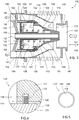
- FIG. 3 schematically shows an example embodiment of an exhaust gas pressure regulator 100 according to the disclosure.
- Exhaust gas is introduced at an inlet end 102 and flows through the pressure regulator to an outlet end 104.
- An exhaust gas flow duct 106 is formed between the inlet end 102 and the outlet end 104, which flow duct serves to diffuse the exhaust gas as will be further explained below.
- the exhaust gas flow duct 106 forms an annular conduit which has an outer periphery being defined by an inner surface 107 of the regulator housing 108 and, and an inner periphery being defined by an outer surface 109 of the inner diffuser assembly 110, which is arranged inside the arranged inside the regulator housing 108.
- the outer diameter of the inner diffuser assembly 110 is less than the inner diameter of the regulator housing 108, such that exhaust gas flows in the volume formed between these two components 108, 110, i.e. in the exhaust gas flow duct 106.
- the regulator housing 108 has a longitudinal extension such that it extends in the same direction as an exhaust gas flow, i.e. from the inlet end 102 towards the outlet end 104.
- the diameter of the regulator housing 108 is preferably varying along its longitudinal direction, such that the cross-sectional area is increasing along the exhaust gas flow direction 101.
- the inner diffuser assembly 110 has a longitudinal extension such that it extends in the same direction as the exhaust gas flow. The diameter of the inner diffuser assembly 110 may vary along its longitudinal direction such that the cross-sectional area is increasing along the exhaust gas flow.
- the inner diffuser assembly 110 may thus have a conical shape, or a shape slightly deviating from a strict conical shape as indicated in Fig. 3 in which a bell shape is presented.
- the regulator housing 108 may have a conical shape, or a shape slightly deviating from a strict conical shape as indicated in Fig. 3 , in which a semi dome shape is shown.
- the regulator housing 108 and the inner diffuser assembly 110 are preferably arranged such that the width of the annular gas flow duct 106 is substantially constant, or slightly increasing, along the longitudinal extension when the exhaust gas pressure regulator 100 is in its idle position. However, as the diameter of the regulator housing 108 and the diameter of the inner diffuser assembly 110 are increasing along the exhaust gas flow direction, the volume of the gas flow duct 106 will increase along the exhaust gas flow direction 101 whereby a diffusion of the exhaust gas will be provided.
- the inner diffuser assembly 110 comprises a centrally arranged stationary shaft 105, a regulator piston 130 that is slidingly arranged on the shaft 105, and a conical front portion 111 stationary and permanently connected to the shaft 105.
- the regulating piston 130 that is moveable relative to the front portion and the regulator housing between an idle position in which the exhaust gas flow duct is open, and a pressurized position in which the regulating piston at least partly closes the exhaust gas flow duct
- An outlet end 142 of the shaft 140 is fixedly attached to a nozzle unit 150 which forms the outlet end 104 of the exhaust gas pressure regulator 100.
- the nozzle unit 150 further includes a cylindrical portion 152 extending towards the inlet end 102.
- the cylindrical portion 152 is configured to slidingly support an outer surface of the regulating piston 130.
- the piston 130 is arranged coaxially on the shaft 105 and the outer periphery of the piston 130 is sealed against the cylindrical portion 152 of the nozzle unit 150 by means of a seal 141.
- the nozzle unit 150 further has an outer portion 154, arranged radially outwards of said cylindrical portion 152 and forming a circumferential support structure surrounding the cylindrical portion 152.
- the outer portion 154 forms the outer portion of the outlet end 104 of the exhaust gas pressure regulator 100 and is connected to the regulator housing 108.
- the regulator housing 108 includes an outer annular flange 143 that is configured be connect the exhaust gas pressure regulator 100 to an outlet pipe 34 located downstream of the regulator 100 or alternatively directly to an inlet portion of the turbo-compound unit 60.
- the flange may be provided on the outer portion 154 of the nozzle unit 150 instead.
- the exhaust gas pressure regulator 100 further comprises an outer annular flange 147 that is configured to connect the exhaust gas pressure regulator 100 to an inlet pipe 33 located upstream of the regulator 100 or alternatively directly to an outlet portion of turbo-charger unit 50.
- the outer annular flange 147 is provided on an individual part 148 of the exhaust gas pressure regulator 100, which individual part 148 is connected with the regulator housing 108 by means of a corrugated metal tube 149.
- This design enables a large degree of freedom in relative motion between the individual part 148 and regulator housing 108, and vibrations are largely prevented from being transferred between the regulator housing 108 and individual part 148.
- the regulator may thus comprise three individual parts forming the outer surface of the regulator 100, namely the individual part 148, a regulator housing 108 and a nozzle unit 150.
- the regulating piston 130 is urged towards the idle position by the force of a mechanical spring 122, which is configured to abut an internal surface 113 of the conical front portion 111 and a first axial side surface 112 of the regulating piston 130.
- the exhaust gas pressure regulator 100 further comprises a control pressure chamber 164 configured for receiving pressurised air or the like for controlling the position of the regulating piston in the axial direction 118, and thereby also the desired backpressure in gas flow duct 106 is attained.
- the control pressure chamber 164 is defined by a second axial side surface 119 of the regulating piston 130, a portion of the nozzle unit 150 that faces the second axial side surface 119 of the regulating piston, an inner surface of the cylindrical portion 152 of the nozzle unit 150, and an outer surface of the shaft 105.
- One or more hollow connector elements 156 may be provided for connecting the outer portion 154 of the nozzle unit 150 with the inner diffuser assembly 110.
- the at least one hollow connector element 156 is arranged for allowing pressurized air to flow from a pressurised air source into the control pressure chamber 164 of the inner diffuser assembly 110.
- Feeding channels are thus arranged in one or more of the connector elements 156 for guiding the pressurized air into the closed cavity 164, but alternative solutions for feeding pressurized air to the control pressure chamber are possible.
- pressurized air is supplied via the air inlet 162
- a force urging the piston 130 away from the idle position and towards a pressurized position will be generated.
- the connector elements 156 may form guide vanes that are arranged to guide the exhaust flow into a desired flow direction.
- the regulating piston 130 further comprises a sleeve portion 131 in sliding contact with an exterior side of the front portion 111 of the inner diffuser assembly 110.
- an exhaust gas pressure chamber 132 is defined by the inner surface 133 of the substantially conical front portion 111, the first axial side surface 112 of the piston 130 and an outer surface of the shaft 105.
- the regulating piston 130 is moveable relative to the front portion 111 and the regulator housing 108 between an idle position in which the exhaust gas flow duct 106 is open, and a pressurized position in which the regulating piston 130 at least partly closes the exhaust gas flow duct 106.
- the closing is performed by controlling the regulating to move towards its pressurized position, thereby rendering the sleeve portion 131 of the regulating piston 130 to move into the exhaust gas flow duct 106, such that the exhaust gas flow duct 106 becomes at least partly closed.
- the sleeve portion 131 may consequently be referred to as a valve sleeve, and the regulating control piston 130 can move axially for regulating the flow area of the exhaust gas flow duct 106 by means of the valve sleeve, against the effect of the helical compression spring 122.
- a annular damping element 172 may be provided between an axial abutment surface of the regulating piston 130 and an opposite axial abutment surface 173 of the front portion 111 of the inner diffuser assembly 110 for damping impact forces between the regulating piston 130 and the front portion 111 of the inner diffuser assembly 110.
- the annular damping element 172 may be a metal textile bushing.
- a distal portion 134 of the sleeve portion 131 may be configured to form part of the outer surface 109 of the inner diffuser assembly 110.
- an inner wall surface of the sleeve portion 131 protrudes into the exhaust gas flow duct 106 between the front portion 111 and the cylindrical portion 152 of the nozzle unit 150.
- the inner diffuser assembly 110 comprises at least one throttled flow passage 144 for enabling pressure equalization of the pressure within the gas flow duct 106 and the exhaust gas pressure chamber 132.
- the throttled flow passage 144 is formed by a passage at the location 135 of the sliding contact between the sleeve portion 131 and the exterior side of the front portion 111 of the inner diffuser assembly 110.
- the pressure within the exhaust gas pressure chamber 132 is substantially static when the regulating piston is arranged in a fixed position.
- the exterior side of the front portion 111 of the inner diffuser assembly 110 comprises a groove 136, in which a sealing ring 137 is located.
- the dimensions of the front portion 111 of the inner diffuser assembly 110 and an interior side of the sleeve portion 131 are also selected such that a radial gap is also formed between an exterior side 138 of the front portion 111 and an interior side of the sleeve portion 131.
- the gap is part of the flow passage 144.
- the size of the gap is sufficient for enabling a leakage flow between the gas flow duct 106 and the exhaust gas pressure chamber 132.
- the total flow area resulting from the gap may be at least 50 mm 2 , specifically at least 100 mm 2 , or in the range of 50 - 1000 mm 2 .
- the sealing ring 137 is configured to at least partly seal the flow passage 144 between the regulating piston and the front portion of the inner diffuser assembly so that the a the flow passage 144 is throttled. This partly sealing of the flow passage 144 is performed by means of a calibrated flow leakage past the sealing ring 137.
- One example solution for accomplishing the calibrated flow leakage past the sealing ring 137 is to provide sealing ring in form of a piston ring that has an annular gap 145 between circumferential ends of the piston ring.
- the appropriate circumferential length 146 of the arc-shaped gap between the circumferential ends of the piston ring may be in the range of 2-50 mm, specifically in the range of 3 - 25 mm, and more specifically in the range of 5 - 20 mm.
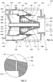
- the regulating control piston 130 When the exhaust gas pressure regulator 100 is activated, i.e. when pressurized media is supplied to the control pressure chamber 164, the regulating control piston 130 begins to move axially against the effect of the helical compression spring 122, and the the sleeve portion 131 begins to protrude into the exhaust gas flow duct 106 until it has reached its pressurized position, in which it at least partly closes the exhaust gas flow duct 106.
- the pressurized position of the regulating piston 130 is shown in FIG. 6 .
- the supplied pressure medium may for example have a pressure in the range about 0.5-10 bar.
- the pressure upstream of the regulating valve is propagated with a certain delay into the exhaust gas pressure chamber 132 via the throttled flow passage 144.
- the regulating piston 130 Upon approaching a pressure balance between the pressure within the control pressure chamber 164 and the exhaust gas pressure chamber 132, the regulating piston 130 will displace towards the idle position, such that a certain flow of exhaust gas is allowed past the the sleeve portion 131.
- the pressure upstream of the sleeve portion 131 decreases. Soon a pressure balance will arise and the regulating piston 130 finds a position of equilibrium.
- the exhaust gas pressure regulator 100 described above is thus self-regulating and automatically provides a backpressure level in similar to the control pressure level.
- the solution using the sealing ring 137 for accomplishing the desired calibrated flow passage 144 between the gas flow duct 106 and the exhaust gas pressure chamber 132 is advantageous because the flow area of the flow passage can easily be adapted by means of mounting a different piston ring.
- the advantage of the disclosure in terms of increased reliability and reduced damages to the regulator 100 may alternatively be obtained by other means (not covered by the claims) of accomplishing a calibrated flow passage.
- the front portion 111 of the exhaust gas pressure regulator 100 may be provided with an aperture 161 at an appropriate location for enabling the desired calibrated flow passage 144 between the gas flow duct 106 and the exhaust gas pressure chamber 132, as schematically illustrated in FIG. 7 .
- the size of the aperture 161 is thus relevant for obtaining the desired pressure throttling effect.
- the aperture may alternatively be provided in the shaft 105 or another part forming a wall of the exhaust gas pressure chamber 132.
- FIG. 8 A simplified example of such a regular periodical pressure pattern 165 in the exhaust gas flow is schematically shown in FIG. 8 .
- the pressure pattern may have a certain amplitude 166 and a certain periodical length 167.
- a real life pressure pattern will most likely have a regular periodical pressure pattern that is less similar to a sinus function.
- the regular periodical exhaust gas pressure patterns may coincide or be a multiple of a resonance frequency of the regulating piston 130 and spring 122 assembly in the pressurized position, or an intermediate state between the idle position and pressurized position. Consequently, there is a risk that the regulating piston 130 starts oscillating with a high amplitude at certain engine operating conditions, thereby potentially damaging the regulating piston 130, the spring 122 and/or the nozzle 150 of the regulator 100.
- the sensitivity of the regulating piston for being influenced by the periodical pressure pattern can be reduced by reducing the amplitude 166 of the pressure pattern. This may be performed by reducing the effective surface area of the regulating piston 130 that is exposed to the exhaust gas pressure pattern 165. However, simply reducing the effective surface area may result in that the desired self-regulation of the regulating piston is lost or at least impaired.
- the solution according to the disclosure includes providing the regulator 100 with an exhaust gas pressure chamber 132 that exhibits about the same average pressure as the exhaust gas pressure pattern 165 but with a reduced amplitude, and having at least a portion of the effective surface area of the regulating piston 130 being exposed to the small amplitude pressure of the exhaust gas pressure chamber 132. Thereby, the amount of effective surface area of the regulating piston 130 that is exposed to the high amplitude exhaust gas pressure pattern 165 is reduced while maintaining the self-regulation functionality of the regulator 100.
- Accomplishing an exhaust gas pressure chamber 132 that exhibits about the same average pressure as the exhaust gas pressure pattern 165 but with a reduced amplitude may be performed by providing the inner diffuser assembly 110 with at least one throttled flow passage 144 for enabling pressure equalization of the pressure within the gas flow duct 106 and the exhaust gas pressure chamber 132.
- the throttled flow passage is configured to filter the large amplitude pressure pattern of the exhaust gas while still allowing an equalizing of the pressure of the gas flow duct 106 and the exhaust gas pressure chamber 132.
- the filtration and pressure equalization is performed by providing a controlled leakage area between the gas flow duct 106 and the exhaust gas pressure chamber 132.
- the effective piston surface area that is exposed to the high amplitude pressure patterns of the exhaust as may be significantly decreased, depending on the proportion of the effective surface area of the regulating piston being exposed to high amplitude pressure pattern and low amplitude pressure.
- the effective surface area of the regulating piston 130 that is exposed to high amplitude pressure pattern of the exhaust gas is shown with dotted force vectors 168, and the effective surface area of the regulating piston 130 that is exposed to low amplitude pressure pattern of the exhaust gas pressure chamber 132 is shown with solid force vectors 169.
- the proportion of the total amount of effective surface area of the regulating piston that may be exposed to the high amplitude exhaust gas in the exhaust gas flow duct is significantly less 50%.
- effective surface area of the regulating piston herein refers to the surface of the regulating piston that may induce an axial force on the regulating piston when exposed to a pressure medium.
- FIG. 8 A schematic and simplified illustration of the pressure pattern 170 within the exhaust gas pressure chamber 132 is illustrated in FIG. 8 for a regulator 100 having a certain leakage flow 144.
- the amplitude 171 is significantly reduced (dampened) and the average pressure is substantially identical to the average pressure of the gas exhaust flow.
- the at least one throttled flow passage is thus configured to essentially form a low-pass filter for the dynamic pressure pulsations in the exhaust gas flow duct, where the high frequency pressure variations, such as for example pressure variations having a frequency above 10 Hz, specifically above 1 Hz, are damped.
- the pressure within the exhaust gas pressure chamber 132 will mainly exhibit a low frequency pressure variation, such as for example below 10 Hz, specifically below 1 Hz. Pressure variations with such low frequency may be considered representing mainly the average pressure in the exhaust gas flow duct over a certain time period.
- the throttled flow passage may as an alternative be configured such that a degree of pressure attenuation of the high frequency components, i.e. frequencies above for example 10 Hz, specifically above 1 Hz, of the dynamic pressure pulsations in the exhaust gas flow duct is at least -6 dB, specifically at least -10 dB, and more specifically at least -20 db.
- the amplitude of the example pressure pattern 170 within the exhaust gas pressure chamber 132 shown in FIG. 8 is damped with about -20 dB.
- the exhaust gas pressure regulator 100 may preferably be used for braking of a vehicle without necessarily using the friction brakes.
- a specific braking force is requested.
- An ECU of the vehicle may then calculate a corresponding air pressure which forces the regulating piston 130 to move, whereby the regulating piston 130 may at least partly close the exhaust gas duct 106 of the exhaust gas pressure regulator 100.
- the air pressure may for example be in the range of 1 to 10 Bars, overcoming the spring force as well as the exhaust gas pressure.
- the exhaust gas pressure regulator 100 is used in engine heat mode when it is desired to increase the temperature of the exhaust gas.
- an ECU of the vehicle will calculate the desired through flow of exhaust gas for providing the desired temperature, and subsequently apply a corresponding pressure level in the control pressure chamber 164
- the exhaust gas pressure regulator 100 has been described to operate in series with a turbo-charger unit 50 and a turbo-compound unit 60, it is readily understood that other applications may also be suitable for the proposed exhaust gas pressure regulator 100.
- the presented exhaust gas pressure regulator may be arranged in any application where a radial turbine, e.g. of a turbo-charger unit, is followed by an axial turbine, e.g. of a turbo-compound unit or a further turbo-charger unit.
- the exhaust gas pressure regulator 100 may be used in association with all kinds of piston engines, from one cylinder and upwards, and with two-stroke or four- stroke engines, for road vehicles, marine equipment, etc.
- a pneumatic system for operating the exhaust gas pressure regulator 100 has been described, other means such as mechanical and/or hydraulic may also be implemented.
Landscapes
- Engineering & Computer Science (AREA)
- Chemical & Material Sciences (AREA)
- Combustion & Propulsion (AREA)
- Mechanical Engineering (AREA)
- General Engineering & Computer Science (AREA)
- Control Of Fluid Pressure (AREA)
Claims (15)
- Abgasdruckregler (100) für einen Verbrennungsmotor (10), wobei der Regler (100) ein Reglergehäuse (108) und eine innere Diffusoranordnung (110) umfasst, die im Inneren des Reglergehäuses (108) angeordnet ist, so dass ein Abgasströmungskanal (106) zwischen einer Innenfläche (107) des Reglergehäuses (108) und einer Außenfläche (109) der inneren Diffusoranordnung (110) gebildet wird, wobei die innere Diffusoranordnung (110) einen vorderen Abschnitt (111) und einen Regelkolben (130) aufweist, der bezüglich des vorderen Abschnitts (111) und des Reglergehäuses (108) zwischen einer Ruhestellung, in der der Abgasströmungskanal (106) offen ist, und einer Druckposition, in der der Regelkolben (130) den Abgasströmungskanal (106) wenigstens teilweise schließt, bewegbar ist, wobei die innere Diffusoranordnung (110) wenigstens einen gedrosselten Strömungsweg (144) zwischen dem Gasströmungskanal (106) und einer Abgasdruckkammer (132) umfasst, die durch den Regelkolben (130) und eine Innenfläche (113) des vorderen Abschnitts (111) definiert ist, dadurch gekennzeichnet, dass die innere Diffusoranordnung (110) einen Dichtungsring (137) umfasst, der dafür ausgebildet ist, einen Strömungsweg zwischen dem Regelkolben (130) und dem vorderen Abschnitt (111) der inneren Diffusoranordnung (110) teilweise abzudichten, so dass der wenigstens eine gedrosselte Strömungsweg (144) mittels einer kalibrierten Strömungsleckage an dem Dichtungsring (137) vorbei vorgesehen ist, und dass der wenigstens eine gedrosselte Strömungsweg (144) dafür ausgebildet ist, einen Tiefpassfilter für dynamische Druckpulsationen in dem Abgasströmungskanal (106) zu bilden, wobei der wenigstens eine gedrosselte Strömungsweg (144) so ausgebildet ist, dass ein durchschnittliches Druckniveau innerhalb der Abgasdruckkammer (132) im Wesentlichen einem durchschnittlichen Abgasdruckniveau des Abgasstroms an einem Einlass zu dem gedrosselten Strömungsweg (144) entspricht, und/oder der gesamte gedrosselte Strömungsweg (144) dafür ausgebildet ist, dass ein Grad der Druckdämpfung der Hochfrequenzkomponenten der dynamischen Druckpulsationen in dem Abgasströmungskanal (106) wenigstens -6 dB, speziell wenigstens -10 dB, und noch spezieller wenigstens -20 dB beträgt.
- Abgasdruckregler nach Anspruch 1, dadurch gekennzeichnet, dass ein gesamter gedrosselter Strömungsweg (144) der inneren Diffusoranordnung (110) einen Durchflussquerschnitt im Bereich von 0,5-10 mm2, speziell im Bereich von 1-6 mm2, und noch spezieller im Bereich von 2-4 mm2 hat.
- Abgasdruckregler nach Anspruch 1, dadurch gekennzeichnet, dass der Dichtungsring (137) ein Metallkolbenring ist.
- Abgasdruckregler nach Anspruch 3, dadurch gekennzeichnet, dass der Metallkolbenring in befestigtem Zustand einen Spalt (145) zwischen den Umfangsenden des Kolbenrings aufweist.
- Abgasdruckregler nach einem der vorhergehenden Ansprüche, dadurch gekennzeichnet, dass eine Gesamtgröße der Wirkfläche des Regelkolbens (130), die für das Abgas in dem Abgasströmungskanal (106) zugänglich ist, um eine axiale Kraft auf den Regelkolben (130) in Richtung des Auslasses des Reglergehäuses (108) aufzubringen, weniger als 75% einer Gesamtgröße der Wirkfläche des Regelkolbens (130) beträgt, die für das Abgas innerhalb der Abgasdruckkammer (132) zugänglich ist, um eine axiale Kraft auf den Regelkolben (130) in Richtung des Auslasses des Reglergehäuses (108) aufzubringen, speziell weniger als 50%, und noch spezieller weniger als 30%.
- Abgasdruckregler nach einem der vorhergehenden Ansprüche, dadurch gekennzeichnet, dass der vordere Abschnitt (111) stationär in dem Reglergehäuse (108) angeordnet ist.
- Abgasdruckregler nach einem der vorhergehenden Ansprüche, dadurch gekennzeichnet, dass der Abgasdruckregler (100) weiterhin eine Steuerdrucckammer (164) umfasst, die durch den Regelkolben (130), eine Düseneinheit (150) und eine Welle (105) definiert ist, wobei ein mit Druck beaufschlagtes Medium innerhalb der Steuerdruckkammer (164) dafür vorgesehen ist, eine Kraft auf den Regelkolben (130) in Richtung der Druckposition aufzubringen, und der Druckregler (100) weiterhin einen Druckmedium-Strömungsweg umfasst, um mit Druck beaufschlagtes Medium von einer äußeren Druckmediumquelle zu der Steuerdruckkammer (164) zuzuführen.
- Abgasdruckregler nach einem der vorhergehenden Ansprüche, dadurch gekennzeichnet, dass der vordere Abschnitt (111) der inneren Diffusoranordnung (110) ein geschlossenes Ende, das einem Abgasströmungseinlass des Abgasdruckreglers (100) zugewandt ist, sowie ein offenes Ende aufweist, das einem Abgasauslass des Abgasdruckreglers (100) zugewandt ist, wobei ein ringförmiges Dämpfungselement (172) zwischen einer axialen Anlagefläche des Regelkolbens (130) und einer gegenüberliegenden axialen Anlagefläche des vorderen Abschnitts (111) der inneren Diffusoranordnung (110) zum Dämpfen der Schlagkräfte zwischen dem Regelkolben (130) und dem vorderen Abschnitt (111) der inneren Diffusoranordnung (110) vorgesehen ist.
- Abgasdruckregler nach Anspruch 8, dadurch gekennzeichnet, dass der vordere Abschnitt (111) der inneren Diffusoranordnung (110) eine konische Form mit einem sich insgesamt vergrößernden Außendurchmesser in der axialen Richtung (118) von dem geschlossenen Ende zu dem offenen Ende hat und die gegenüberliegende axiale Anlagefläche des vorderen Abschnitts (111) der inneren Diffusoranordnung (110) in einem radial äußeren Bereich angeordnet ist, der nahe oder an dem offenen Ende angeordnet ist.
- Abgasdruckregler nach einem der vorhergehenden Ansprüche, dadurch gekennzeichnet, dass sowohl eine innere Querschnittsfläche, die von der Innenfläche (107) eines Reglergehäuses (108) definiert ist, als auch ein Außendurchmesser der inneren Diffusoranordnung (110) sich in axialer Richtung (118) zu einem Auslass des Abgasdruckreglers (100) vergrößern und die innere Diffusoranordnung (100) konzentrisch innerhalb der Innenfläche (107) eines Reglergehäuses (108) angeordnet ist.
- Abgassystem für einen Verbrennungsmotor, dadurch gekennzeichnet, dass das Abgassystem einen Gasdruckregler (100) nach einem der vorhergehenden Ansprüche 1 bis 10 umfasst, der einer ersten Turbineneinheit nachgelagert und einer zweiten Turbineneinheit vorgelagert ist.
- Abgassystem nach Anspruch 11, dadurch gekennzeichnet, dass die innere Diffusoranordnung (110) eine Düse für die zweite Turbineneinheit bildet.
- Abgassystem nach Anspruch 11 oder Anspruch 12, dadurch gekennzeichnet, dass die zweite Turbineneinheit eine Turbocompound-Einheit (60) ist.
- Verbrennungsmotor (10), umfassend ein Abgassystem nach einem der vorhergehenden Ansprüche 11 bis 13.
- Fahrzeug, umfassend einen Verbrennungsmotor (10) nach Anspruch 14.
Priority Applications (1)
| Application Number | Priority Date | Filing Date | Title |
|---|---|---|---|
| EP19167638.6A EP3540193B1 (de) | 2015-05-29 | 2015-05-29 | Abgasdruckregler für einen verbrennungsmotor |
Applications Claiming Priority (1)
| Application Number | Priority Date | Filing Date | Title |
|---|---|---|---|
| PCT/EP2015/061948 WO2016192749A1 (en) | 2015-05-29 | 2015-05-29 | An exhaust gas pressure regulator for a combustion engine |
Related Child Applications (1)
| Application Number | Title | Priority Date | Filing Date |
|---|---|---|---|
| EP19167638.6A Division EP3540193B1 (de) | 2015-05-29 | 2015-05-29 | Abgasdruckregler für einen verbrennungsmotor |
Publications (2)
| Publication Number | Publication Date |
|---|---|
| EP3303792A1 EP3303792A1 (de) | 2018-04-11 |
| EP3303792B1 true EP3303792B1 (de) | 2019-05-01 |
Family
ID=53298338
Family Applications (2)
| Application Number | Title | Priority Date | Filing Date |
|---|---|---|---|
| EP15727349.1A Active EP3303792B1 (de) | 2015-05-29 | 2015-05-29 | Abgasdruckregler für einen verbrennungsmotor |
| EP19167638.6A Active EP3540193B1 (de) | 2015-05-29 | 2015-05-29 | Abgasdruckregler für einen verbrennungsmotor |
Family Applications After (1)
| Application Number | Title | Priority Date | Filing Date |
|---|---|---|---|
| EP19167638.6A Active EP3540193B1 (de) | 2015-05-29 | 2015-05-29 | Abgasdruckregler für einen verbrennungsmotor |
Country Status (4)
| Country | Link |
|---|---|
| US (1) | US10436107B2 (de) |
| EP (2) | EP3303792B1 (de) |
| CN (1) | CN107690516B (de) |
| WO (1) | WO2016192749A1 (de) |
Families Citing this family (2)
| Publication number | Priority date | Publication date | Assignee | Title |
|---|---|---|---|---|
| CN109356711A (zh) * | 2018-12-12 | 2019-02-19 | 中国北方发动机研究所(天津) | 一种可变排气涡轮 |
| CN115155681B (zh) * | 2022-06-30 | 2023-09-05 | 天津大学 | 无膜激波管及采样系统 |
Family Cites Families (14)
| Publication number | Priority date | Publication date | Assignee | Title |
|---|---|---|---|---|
| US3865128A (en) | 1972-09-08 | 1975-02-11 | Vijay K Zadoo | Pressure regulating and shut-off valve |
| US4283912A (en) * | 1979-06-12 | 1981-08-18 | The Garrett Corporation | Turbocharger control |
| US4703625A (en) * | 1985-02-25 | 1987-11-03 | Ranco Incorporated | Turbocharger control system |
| US6189896B1 (en) | 1999-04-08 | 2001-02-20 | Caterpillar Inc. | Controlled leakage rotating seal ring with elements for receiving and holding a lubricant on a face thereof |
| JP2005325685A (ja) | 2003-05-19 | 2005-11-24 | Mitsubishi Motors Corp | 内燃機関の排圧上昇装置 |
| EP1954929B1 (de) | 2005-11-22 | 2012-02-22 | Volvo Lastvagnar AB | Verbrennungsmotor mit zweistufigem turboladesystem |
| CN200955432Y (zh) | 2006-06-05 | 2007-10-03 | 动力系统工业有限公司 | 汽缸引擎运转排气压力的自动调控装置 |
| CN101548089B (zh) * | 2006-12-22 | 2012-09-05 | 博格华纳公司 | 阀门控制装置 |
| EP2322780B1 (de) * | 2007-12-04 | 2014-06-18 | Caterpillar Motoren GmbH & Co. KG | Abgasüberströmventil mit Ladedrucksteuerung |
| DE102008010658B4 (de) | 2008-02-22 | 2010-08-19 | Knorr-Bremse Systeme für Nutzfahrzeuge GmbH | Abgasregelsystem und Abgasregelverfahren |
| EP2610474B1 (de) | 2011-12-27 | 2015-09-09 | BorgWarner Esslingen GmbH | Niederdruck-Abgasrückführventil |
| US9447697B2 (en) * | 2013-03-15 | 2016-09-20 | Dayco Ip Holdings, Llc | Wastegate valve and turbocharger having same |
| WO2014154226A1 (en) | 2013-03-27 | 2014-10-02 | Volvo Truck Corporation | An exhaust gas pressure regulator |
| DE202013010503U1 (de) | 2013-11-20 | 2014-02-20 | Borgwarner Inc. | Steuerdose |
-
2015
- 2015-05-29 EP EP15727349.1A patent/EP3303792B1/de active Active
- 2015-05-29 CN CN201580080422.7A patent/CN107690516B/zh active Active
- 2015-05-29 WO PCT/EP2015/061948 patent/WO2016192749A1/en not_active Ceased
- 2015-05-29 US US15/569,798 patent/US10436107B2/en active Active
- 2015-05-29 EP EP19167638.6A patent/EP3540193B1/de active Active
Non-Patent Citations (1)
| Title |
|---|
| None * |
Also Published As
| Publication number | Publication date |
|---|---|
| EP3540193A1 (de) | 2019-09-18 |
| CN107690516A (zh) | 2018-02-13 |
| WO2016192749A1 (en) | 2016-12-08 |
| CN107690516B (zh) | 2020-04-03 |
| US20180135510A1 (en) | 2018-05-17 |
| EP3303792A1 (de) | 2018-04-11 |
| US10436107B2 (en) | 2019-10-08 |
| EP3540193B1 (de) | 2021-07-28 |
Similar Documents
| Publication | Publication Date | Title |
|---|---|---|
| US8627934B2 (en) | Fluid transmission device | |
| JP5721442B2 (ja) | 排気制御システム及び排気制御法 | |
| JP4354257B2 (ja) | 可変形態タービン | |
| JP2009512809A (ja) | 可変形態タービン | |
| JP3851923B2 (ja) | 内燃エンジン用排気ガスターボチャージャー | |
| US6925805B2 (en) | Turbocharger | |
| KR20140001942A (ko) | 내연 엔진용 터보 과급기 동작 시스템과 방법 | |
| KR20010020489A (ko) | 내연기관을 구비한 차량의 배기가스 회로에 장착된 감속장치 | |
| EP3540193B1 (de) | Abgasdruckregler für einen verbrennungsmotor | |
| US12320345B2 (en) | Apparatus for damping pressure pulsation for a compressor of a gaseous fluid | |
| JP2005535836A (ja) | 内燃エンジン用排気ガスターボチャージャー | |
| KR20130103490A (ko) | 유체 송출용 피스톤 펌프 및 관련 차량 브레이크 시스템 | |
| EP2978955B1 (de) | Abgasdruckregler | |
| CN113825906A (zh) | 活塞式泵驱动装置 | |
| JP6853637B2 (ja) | 減衰弁およびシリンダ装置 | |
| KR20010020490A (ko) | 내연기관이 탑재된 차량의 배기가스 회로내에 설치되는감속장치 | |
| KR100299297B1 (ko) | 스로틀부재를가지는유압식토크컨버터 | |
| CN110785549B (zh) | 增压器 | |
| JP3389823B2 (ja) | 圧力流体配管の脈動減衰構造 | |
| CN101223337B (zh) | 几何构造可变涡轮 | |
| CN109281974B (zh) | 一种基于共振方式的频率敏感阻尼油气弹簧 | |
| CN102239076B (zh) | 液压动力转向器 | |
| US10458298B2 (en) | Exhaust gas system for an internal combustion engine | |
| CN111486203A (zh) | 皮带张紧机构 | |
| CN121399392A (zh) | 包括阻尼装置的致动装置以及包括该致动装置的液压致动系统 |
Legal Events
| Date | Code | Title | Description |
|---|---|---|---|
| STAA | Information on the status of an ep patent application or granted ep patent |
Free format text: STATUS: THE INTERNATIONAL PUBLICATION HAS BEEN MADE |
|
| PUAI | Public reference made under article 153(3) epc to a published international application that has entered the european phase |
Free format text: ORIGINAL CODE: 0009012 |
|
| STAA | Information on the status of an ep patent application or granted ep patent |
Free format text: STATUS: REQUEST FOR EXAMINATION WAS MADE |
|
| 17P | Request for examination filed |
Effective date: 20171124 |
|
| AK | Designated contracting states |
Kind code of ref document: A1 Designated state(s): AL AT BE BG CH CY CZ DE DK EE ES FI FR GB GR HR HU IE IS IT LI LT LU LV MC MK MT NL NO PL PT RO RS SE SI SK SM TR |
|
| AX | Request for extension of the european patent |
Extension state: BA ME |
|
| DAV | Request for validation of the european patent (deleted) | ||
| DAX | Request for extension of the european patent (deleted) | ||
| REG | Reference to a national code |
Ref country code: DE Ref legal event code: R079 Ref document number: 602015029294 Country of ref document: DE Free format text: PREVIOUS MAIN CLASS: F01N0013080000 Ipc: F02B0037000000 |
|
| GRAP | Despatch of communication of intention to grant a patent |
Free format text: ORIGINAL CODE: EPIDOSNIGR1 |
|
| STAA | Information on the status of an ep patent application or granted ep patent |
Free format text: STATUS: GRANT OF PATENT IS INTENDED |
|
| RIC1 | Information provided on ipc code assigned before grant |
Ipc: F02B 37/013 20060101ALI20180907BHEP Ipc: F02B 37/22 20060101ALI20180907BHEP Ipc: F02D 9/06 20060101ALI20180907BHEP Ipc: F02B 37/24 20060101ALI20180907BHEP Ipc: F02B 37/18 20060101ALI20180907BHEP Ipc: F01N 13/08 20100101ALI20180907BHEP Ipc: F02D 9/12 20060101ALI20180907BHEP Ipc: F02B 37/00 20060101AFI20180907BHEP |
|
| INTG | Intention to grant announced |
Effective date: 20181009 |
|
| GRAS | Grant fee paid |
Free format text: ORIGINAL CODE: EPIDOSNIGR3 |
|
| GRAJ | Information related to disapproval of communication of intention to grant by the applicant or resumption of examination proceedings by the epo deleted |
Free format text: ORIGINAL CODE: EPIDOSDIGR1 |
|
| GRAL | Information related to payment of fee for publishing/printing deleted |
Free format text: ORIGINAL CODE: EPIDOSDIGR3 |
|
| STAA | Information on the status of an ep patent application or granted ep patent |
Free format text: STATUS: REQUEST FOR EXAMINATION WAS MADE |
|
| INTC | Intention to grant announced (deleted) | ||
| GRAR | Information related to intention to grant a patent recorded |
Free format text: ORIGINAL CODE: EPIDOSNIGR71 |
|
| STAA | Information on the status of an ep patent application or granted ep patent |
Free format text: STATUS: GRANT OF PATENT IS INTENDED |
|
| GRAA | (expected) grant |
Free format text: ORIGINAL CODE: 0009210 |
|
| STAA | Information on the status of an ep patent application or granted ep patent |
Free format text: STATUS: THE PATENT HAS BEEN GRANTED |
|
| AK | Designated contracting states |
Kind code of ref document: B1 Designated state(s): AL AT BE BG CH CY CZ DE DK EE ES FI FR GB GR HR HU IE IS IT LI LT LU LV MC MK MT NL NO PL PT RO RS SE SI SK SM TR |
|
| INTG | Intention to grant announced |
Effective date: 20190322 |
|
| REG | Reference to a national code |
Ref country code: GB Ref legal event code: FG4D |
|
| REG | Reference to a national code |
Ref country code: CH Ref legal event code: EP Ref country code: AT Ref legal event code: REF Ref document number: 1127200 Country of ref document: AT Kind code of ref document: T Effective date: 20190515 |
|
| REG | Reference to a national code |
Ref country code: DE Ref legal event code: R096 Ref document number: 602015029294 Country of ref document: DE |
|
| REG | Reference to a national code |
Ref country code: IE Ref legal event code: FG4D |
|
| REG | Reference to a national code |
Ref country code: NL Ref legal event code: MP Effective date: 20190501 |
|
| REG | Reference to a national code |
Ref country code: LT Ref legal event code: MG4D |
|
| PG25 | Lapsed in a contracting state [announced via postgrant information from national office to epo] |
Ref country code: NO Free format text: LAPSE BECAUSE OF FAILURE TO SUBMIT A TRANSLATION OF THE DESCRIPTION OR TO PAY THE FEE WITHIN THE PRESCRIBED TIME-LIMIT Effective date: 20190801 Ref country code: LT Free format text: LAPSE BECAUSE OF FAILURE TO SUBMIT A TRANSLATION OF THE DESCRIPTION OR TO PAY THE FEE WITHIN THE PRESCRIBED TIME-LIMIT Effective date: 20190501 Ref country code: HR Free format text: LAPSE BECAUSE OF FAILURE TO SUBMIT A TRANSLATION OF THE DESCRIPTION OR TO PAY THE FEE WITHIN THE PRESCRIBED TIME-LIMIT Effective date: 20190501 Ref country code: SE Free format text: LAPSE BECAUSE OF FAILURE TO SUBMIT A TRANSLATION OF THE DESCRIPTION OR TO PAY THE FEE WITHIN THE PRESCRIBED TIME-LIMIT Effective date: 20190501 Ref country code: FI Free format text: LAPSE BECAUSE OF FAILURE TO SUBMIT A TRANSLATION OF THE DESCRIPTION OR TO PAY THE FEE WITHIN THE PRESCRIBED TIME-LIMIT Effective date: 20190501 Ref country code: PT Free format text: LAPSE BECAUSE OF FAILURE TO SUBMIT A TRANSLATION OF THE DESCRIPTION OR TO PAY THE FEE WITHIN THE PRESCRIBED TIME-LIMIT Effective date: 20190901 Ref country code: AL Free format text: LAPSE BECAUSE OF FAILURE TO SUBMIT A TRANSLATION OF THE DESCRIPTION OR TO PAY THE FEE WITHIN THE PRESCRIBED TIME-LIMIT Effective date: 20190501 Ref country code: ES Free format text: LAPSE BECAUSE OF FAILURE TO SUBMIT A TRANSLATION OF THE DESCRIPTION OR TO PAY THE FEE WITHIN THE PRESCRIBED TIME-LIMIT Effective date: 20190501 Ref country code: NL Free format text: LAPSE BECAUSE OF FAILURE TO SUBMIT A TRANSLATION OF THE DESCRIPTION OR TO PAY THE FEE WITHIN THE PRESCRIBED TIME-LIMIT Effective date: 20190501 |
|
| PG25 | Lapsed in a contracting state [announced via postgrant information from national office to epo] |
Ref country code: BG Free format text: LAPSE BECAUSE OF FAILURE TO SUBMIT A TRANSLATION OF THE DESCRIPTION OR TO PAY THE FEE WITHIN THE PRESCRIBED TIME-LIMIT Effective date: 20190801 Ref country code: RS Free format text: LAPSE BECAUSE OF FAILURE TO SUBMIT A TRANSLATION OF THE DESCRIPTION OR TO PAY THE FEE WITHIN THE PRESCRIBED TIME-LIMIT Effective date: 20190501 Ref country code: LV Free format text: LAPSE BECAUSE OF FAILURE TO SUBMIT A TRANSLATION OF THE DESCRIPTION OR TO PAY THE FEE WITHIN THE PRESCRIBED TIME-LIMIT Effective date: 20190501 Ref country code: GR Free format text: LAPSE BECAUSE OF FAILURE TO SUBMIT A TRANSLATION OF THE DESCRIPTION OR TO PAY THE FEE WITHIN THE PRESCRIBED TIME-LIMIT Effective date: 20190802 |
|
| REG | Reference to a national code |
Ref country code: AT Ref legal event code: MK05 Ref document number: 1127200 Country of ref document: AT Kind code of ref document: T Effective date: 20190501 |
|
| REG | Reference to a national code |
Ref country code: CH Ref legal event code: PL |
|
| PG25 | Lapsed in a contracting state [announced via postgrant information from national office to epo] |
Ref country code: IS Free format text: LAPSE BECAUSE OF FAILURE TO SUBMIT A TRANSLATION OF THE DESCRIPTION OR TO PAY THE FEE WITHIN THE PRESCRIBED TIME-LIMIT Effective date: 20190901 |
|
| PG25 | Lapsed in a contracting state [announced via postgrant information from national office to epo] |
Ref country code: RO Free format text: LAPSE BECAUSE OF FAILURE TO SUBMIT A TRANSLATION OF THE DESCRIPTION OR TO PAY THE FEE WITHIN THE PRESCRIBED TIME-LIMIT Effective date: 20190501 Ref country code: SK Free format text: LAPSE BECAUSE OF FAILURE TO SUBMIT A TRANSLATION OF THE DESCRIPTION OR TO PAY THE FEE WITHIN THE PRESCRIBED TIME-LIMIT Effective date: 20190501 Ref country code: EE Free format text: LAPSE BECAUSE OF FAILURE TO SUBMIT A TRANSLATION OF THE DESCRIPTION OR TO PAY THE FEE WITHIN THE PRESCRIBED TIME-LIMIT Effective date: 20190501 Ref country code: LI Free format text: LAPSE BECAUSE OF NON-PAYMENT OF DUE FEES Effective date: 20190531 Ref country code: AT Free format text: LAPSE BECAUSE OF FAILURE TO SUBMIT A TRANSLATION OF THE DESCRIPTION OR TO PAY THE FEE WITHIN THE PRESCRIBED TIME-LIMIT Effective date: 20190501 Ref country code: DK Free format text: LAPSE BECAUSE OF FAILURE TO SUBMIT A TRANSLATION OF THE DESCRIPTION OR TO PAY THE FEE WITHIN THE PRESCRIBED TIME-LIMIT Effective date: 20190501 Ref country code: MC Free format text: LAPSE BECAUSE OF FAILURE TO SUBMIT A TRANSLATION OF THE DESCRIPTION OR TO PAY THE FEE WITHIN THE PRESCRIBED TIME-LIMIT Effective date: 20190501 Ref country code: CH Free format text: LAPSE BECAUSE OF NON-PAYMENT OF DUE FEES Effective date: 20190531 Ref country code: CZ Free format text: LAPSE BECAUSE OF FAILURE TO SUBMIT A TRANSLATION OF THE DESCRIPTION OR TO PAY THE FEE WITHIN THE PRESCRIBED TIME-LIMIT Effective date: 20190501 |
|
| REG | Reference to a national code |
Ref country code: DE Ref legal event code: R097 Ref document number: 602015029294 Country of ref document: DE |
|
| REG | Reference to a national code |
Ref country code: BE Ref legal event code: MM Effective date: 20190531 |
|
| PG25 | Lapsed in a contracting state [announced via postgrant information from national office to epo] |
Ref country code: IT Free format text: LAPSE BECAUSE OF FAILURE TO SUBMIT A TRANSLATION OF THE DESCRIPTION OR TO PAY THE FEE WITHIN THE PRESCRIBED TIME-LIMIT Effective date: 20190501 Ref country code: SM Free format text: LAPSE BECAUSE OF FAILURE TO SUBMIT A TRANSLATION OF THE DESCRIPTION OR TO PAY THE FEE WITHIN THE PRESCRIBED TIME-LIMIT Effective date: 20190501 Ref country code: LU Free format text: LAPSE BECAUSE OF NON-PAYMENT OF DUE FEES Effective date: 20190529 |
|
| PLBE | No opposition filed within time limit |
Free format text: ORIGINAL CODE: 0009261 |
|
| STAA | Information on the status of an ep patent application or granted ep patent |
Free format text: STATUS: NO OPPOSITION FILED WITHIN TIME LIMIT |
|
| PG25 | Lapsed in a contracting state [announced via postgrant information from national office to epo] |
Ref country code: TR Free format text: LAPSE BECAUSE OF FAILURE TO SUBMIT A TRANSLATION OF THE DESCRIPTION OR TO PAY THE FEE WITHIN THE PRESCRIBED TIME-LIMIT Effective date: 20190501 |
|
| 26N | No opposition filed |
Effective date: 20200204 |
|
| GBPC | Gb: european patent ceased through non-payment of renewal fee |
Effective date: 20190801 |
|
| PG25 | Lapsed in a contracting state [announced via postgrant information from national office to epo] |
Ref country code: IE Free format text: LAPSE BECAUSE OF NON-PAYMENT OF DUE FEES Effective date: 20190529 Ref country code: PL Free format text: LAPSE BECAUSE OF FAILURE TO SUBMIT A TRANSLATION OF THE DESCRIPTION OR TO PAY THE FEE WITHIN THE PRESCRIBED TIME-LIMIT Effective date: 20190501 |
|
| PG25 | Lapsed in a contracting state [announced via postgrant information from national office to epo] |
Ref country code: BE Free format text: LAPSE BECAUSE OF NON-PAYMENT OF DUE FEES Effective date: 20190531 Ref country code: SI Free format text: LAPSE BECAUSE OF FAILURE TO SUBMIT A TRANSLATION OF THE DESCRIPTION OR TO PAY THE FEE WITHIN THE PRESCRIBED TIME-LIMIT Effective date: 20190501 |
|
| PG25 | Lapsed in a contracting state [announced via postgrant information from national office to epo] |
Ref country code: GB Free format text: LAPSE BECAUSE OF NON-PAYMENT OF DUE FEES Effective date: 20190801 |
|
| PG25 | Lapsed in a contracting state [announced via postgrant information from national office to epo] |
Ref country code: CY Free format text: LAPSE BECAUSE OF FAILURE TO SUBMIT A TRANSLATION OF THE DESCRIPTION OR TO PAY THE FEE WITHIN THE PRESCRIBED TIME-LIMIT Effective date: 20190501 |
|
| PG25 | Lapsed in a contracting state [announced via postgrant information from national office to epo] |
Ref country code: HU Free format text: LAPSE BECAUSE OF FAILURE TO SUBMIT A TRANSLATION OF THE DESCRIPTION OR TO PAY THE FEE WITHIN THE PRESCRIBED TIME-LIMIT; INVALID AB INITIO Effective date: 20150529 Ref country code: MT Free format text: LAPSE BECAUSE OF FAILURE TO SUBMIT A TRANSLATION OF THE DESCRIPTION OR TO PAY THE FEE WITHIN THE PRESCRIBED TIME-LIMIT Effective date: 20190501 |
|
| PG25 | Lapsed in a contracting state [announced via postgrant information from national office to epo] |
Ref country code: MK Free format text: LAPSE BECAUSE OF FAILURE TO SUBMIT A TRANSLATION OF THE DESCRIPTION OR TO PAY THE FEE WITHIN THE PRESCRIBED TIME-LIMIT Effective date: 20190501 |
|
| PGFP | Annual fee paid to national office [announced via postgrant information from national office to epo] |
Ref country code: FR Payment date: 20240527 Year of fee payment: 10 |
|
| PG25 | Lapsed in a contracting state [announced via postgrant information from national office to epo] |
Ref country code: FR Free format text: LAPSE BECAUSE OF NON-PAYMENT OF DUE FEES Effective date: 20250531 |
|
| PGFP | Annual fee paid to national office [announced via postgrant information from national office to epo] |
Ref country code: DE Payment date: 20260522 Year of fee payment: 12 |