EP3303909B1 - Luminaire à del linéaire utilisable dans des lieux hostiles et dangereux - Google Patents
Luminaire à del linéaire utilisable dans des lieux hostiles et dangereux Download PDFInfo
- Publication number
- EP3303909B1 EP3303909B1 EP16804488.1A EP16804488A EP3303909B1 EP 3303909 B1 EP3303909 B1 EP 3303909B1 EP 16804488 A EP16804488 A EP 16804488A EP 3303909 B1 EP3303909 B1 EP 3303909B1
- Authority
- EP
- European Patent Office
- Prior art keywords
- light fixture
- linear light
- driver
- housing body
- lighting
- Prior art date
- Legal status (The legal status is an assumption and is not a legal conclusion. Google has not performed a legal analysis and makes no representation as to the accuracy of the status listed.)
- Active
Links
Images







Classifications
-
- F—MECHANICAL ENGINEERING; LIGHTING; HEATING; WEAPONS; BLASTING
- F21—LIGHTING
- F21V—FUNCTIONAL FEATURES OR DETAILS OF LIGHTING DEVICES OR SYSTEMS THEREOF; STRUCTURAL COMBINATIONS OF LIGHTING DEVICES WITH OTHER ARTICLES, NOT OTHERWISE PROVIDED FOR
- F21V25/00—Safety devices structurally associated with lighting devices
- F21V25/12—Flameproof or explosion-proof arrangements
-
- F—MECHANICAL ENGINEERING; LIGHTING; HEATING; WEAPONS; BLASTING
- F21—LIGHTING
- F21K—NON-ELECTRIC LIGHT SOURCES USING LUMINESCENCE; LIGHT SOURCES USING ELECTROCHEMILUMINESCENCE; LIGHT SOURCES USING CHARGES OF COMBUSTIBLE MATERIAL; LIGHT SOURCES USING SEMICONDUCTOR DEVICES AS LIGHT-GENERATING ELEMENTS; LIGHT SOURCES NOT OTHERWISE PROVIDED FOR
- F21K9/00—Light sources using semiconductor devices as light-generating elements, e.g. using light-emitting diodes [LED] or lasers
- F21K9/20—Light sources comprising attachment means
- F21K9/27—Retrofit light sources for lighting devices with two fittings for each light source, e.g. for substitution of fluorescent tubes
-
- F—MECHANICAL ENGINEERING; LIGHTING; HEATING; WEAPONS; BLASTING
- F21—LIGHTING
- F21V—FUNCTIONAL FEATURES OR DETAILS OF LIGHTING DEVICES OR SYSTEMS THEREOF; STRUCTURAL COMBINATIONS OF LIGHTING DEVICES WITH OTHER ARTICLES, NOT OTHERWISE PROVIDED FOR
- F21V21/00—Supporting, suspending, or attaching arrangements for lighting devices; Hand grips
- F21V21/02—Wall, ceiling, or floor bases; Fixing pendants or arms to the bases
- F21V21/025—Elongated bases having a U-shaped cross section
-
- F—MECHANICAL ENGINEERING; LIGHTING; HEATING; WEAPONS; BLASTING
- F21—LIGHTING
- F21V—FUNCTIONAL FEATURES OR DETAILS OF LIGHTING DEVICES OR SYSTEMS THEREOF; STRUCTURAL COMBINATIONS OF LIGHTING DEVICES WITH OTHER ARTICLES, NOT OTHERWISE PROVIDED FOR
- F21V23/00—Arrangement of electric circuit elements in or on lighting devices
- F21V23/003—Arrangement of electric circuit elements in or on lighting devices the elements being electronics drivers or controllers for operating the light source, e.g. for a LED array
- F21V23/007—Arrangement of electric circuit elements in or on lighting devices the elements being electronics drivers or controllers for operating the light source, e.g. for a LED array enclosed in a casing
-
- F—MECHANICAL ENGINEERING; LIGHTING; HEATING; WEAPONS; BLASTING
- F21—LIGHTING
- F21V—FUNCTIONAL FEATURES OR DETAILS OF LIGHTING DEVICES OR SYSTEMS THEREOF; STRUCTURAL COMBINATIONS OF LIGHTING DEVICES WITH OTHER ARTICLES, NOT OTHERWISE PROVIDED FOR
- F21V31/00—Gas-tight or water-tight arrangements
- F21V31/005—Sealing arrangements therefor
-
- F—MECHANICAL ENGINEERING; LIGHTING; HEATING; WEAPONS; BLASTING
- F21—LIGHTING
- F21V—FUNCTIONAL FEATURES OR DETAILS OF LIGHTING DEVICES OR SYSTEMS THEREOF; STRUCTURAL COMBINATIONS OF LIGHTING DEVICES WITH OTHER ARTICLES, NOT OTHERWISE PROVIDED FOR
- F21V5/00—Refractors for light sources
- F21V5/04—Refractors for light sources of lens shape
-
- F—MECHANICAL ENGINEERING; LIGHTING; HEATING; WEAPONS; BLASTING
- F21—LIGHTING
- F21S—NON-PORTABLE LIGHTING DEVICES; SYSTEMS THEREOF; VEHICLE LIGHTING DEVICES SPECIALLY ADAPTED FOR VEHICLE EXTERIORS
- F21S8/00—Lighting devices intended for fixed installation
- F21S8/03—Lighting devices intended for fixed installation of surface-mounted type
- F21S8/033—Lighting devices intended for fixed installation of surface-mounted type the surface being a wall or like vertical structure, e.g. building facade
-
- F—MECHANICAL ENGINEERING; LIGHTING; HEATING; WEAPONS; BLASTING
- F21—LIGHTING
- F21S—NON-PORTABLE LIGHTING DEVICES; SYSTEMS THEREOF; VEHICLE LIGHTING DEVICES SPECIALLY ADAPTED FOR VEHICLE EXTERIORS
- F21S8/00—Lighting devices intended for fixed installation
- F21S8/04—Lighting devices intended for fixed installation intended only for mounting on a ceiling or the like overhead structures
-
- F—MECHANICAL ENGINEERING; LIGHTING; HEATING; WEAPONS; BLASTING
- F21—LIGHTING
- F21S—NON-PORTABLE LIGHTING DEVICES; SYSTEMS THEREOF; VEHICLE LIGHTING DEVICES SPECIALLY ADAPTED FOR VEHICLE EXTERIORS
- F21S9/00—Lighting devices with a built-in power supply; Systems employing lighting devices with a built-in power supply
- F21S9/02—Lighting devices with a built-in power supply; Systems employing lighting devices with a built-in power supply the power supply being a battery or accumulator
-
- F—MECHANICAL ENGINEERING; LIGHTING; HEATING; WEAPONS; BLASTING
- F21—LIGHTING
- F21V—FUNCTIONAL FEATURES OR DETAILS OF LIGHTING DEVICES OR SYSTEMS THEREOF; STRUCTURAL COMBINATIONS OF LIGHTING DEVICES WITH OTHER ARTICLES, NOT OTHERWISE PROVIDED FOR
- F21V15/00—Protecting lighting devices from damage
- F21V15/01—Housings, e.g. material or assembling of housing parts
-
- F—MECHANICAL ENGINEERING; LIGHTING; HEATING; WEAPONS; BLASTING
- F21—LIGHTING
- F21V—FUNCTIONAL FEATURES OR DETAILS OF LIGHTING DEVICES OR SYSTEMS THEREOF; STRUCTURAL COMBINATIONS OF LIGHTING DEVICES WITH OTHER ARTICLES, NOT OTHERWISE PROVIDED FOR
- F21V21/00—Supporting, suspending, or attaching arrangements for lighting devices; Hand grips
- F21V21/10—Pendants, arms, or standards; Fixing lighting devices to pendants, arms, or standards
- F21V21/116—Fixing lighting devices to arms or standards
-
- F—MECHANICAL ENGINEERING; LIGHTING; HEATING; WEAPONS; BLASTING
- F21—LIGHTING
- F21V—FUNCTIONAL FEATURES OR DETAILS OF LIGHTING DEVICES OR SYSTEMS THEREOF; STRUCTURAL COMBINATIONS OF LIGHTING DEVICES WITH OTHER ARTICLES, NOT OTHERWISE PROVIDED FOR
- F21V23/00—Arrangement of electric circuit elements in or on lighting devices
- F21V23/001—Arrangement of electric circuit elements in or on lighting devices the elements being electrical wires or cables
-
- F—MECHANICAL ENGINEERING; LIGHTING; HEATING; WEAPONS; BLASTING
- F21—LIGHTING
- F21V—FUNCTIONAL FEATURES OR DETAILS OF LIGHTING DEVICES OR SYSTEMS THEREOF; STRUCTURAL COMBINATIONS OF LIGHTING DEVICES WITH OTHER ARTICLES, NOT OTHERWISE PROVIDED FOR
- F21V23/00—Arrangement of electric circuit elements in or on lighting devices
- F21V23/06—Arrangement of electric circuit elements in or on lighting devices the elements being coupling devices, e.g. connectors
-
- F—MECHANICAL ENGINEERING; LIGHTING; HEATING; WEAPONS; BLASTING
- F21—LIGHTING
- F21V—FUNCTIONAL FEATURES OR DETAILS OF LIGHTING DEVICES OR SYSTEMS THEREOF; STRUCTURAL COMBINATIONS OF LIGHTING DEVICES WITH OTHER ARTICLES, NOT OTHERWISE PROVIDED FOR
- F21V27/00—Cable-stowing arrangements structurally associated with lighting devices, e.g. reels
- F21V27/02—Cable inlets
-
- F—MECHANICAL ENGINEERING; LIGHTING; HEATING; WEAPONS; BLASTING
- F21—LIGHTING
- F21W—INDEXING SCHEME ASSOCIATED WITH SUBCLASSES F21K, F21L, F21S and F21V, RELATING TO USES OR APPLICATIONS OF LIGHTING DEVICES OR SYSTEMS
- F21W2131/00—Use or application of lighting devices or systems not provided for in codes F21W2102/00-F21W2121/00
- F21W2131/10—Outdoor lighting
-
- F—MECHANICAL ENGINEERING; LIGHTING; HEATING; WEAPONS; BLASTING
- F21—LIGHTING
- F21Y—INDEXING SCHEME ASSOCIATED WITH SUBCLASSES F21K, F21L, F21S and F21V, RELATING TO THE FORM OR THE KIND OF THE LIGHT SOURCES OR OF THE COLOUR OF THE LIGHT EMITTED
- F21Y2103/00—Elongate light sources, e.g. fluorescent tubes
- F21Y2103/10—Elongate light sources, e.g. fluorescent tubes comprising a linear array of point-like light-generating elements
-
- F—MECHANICAL ENGINEERING; LIGHTING; HEATING; WEAPONS; BLASTING
- F21—LIGHTING
- F21Y—INDEXING SCHEME ASSOCIATED WITH SUBCLASSES F21K, F21L, F21S and F21V, RELATING TO THE FORM OR THE KIND OF THE LIGHT SOURCES OR OF THE COLOUR OF THE LIGHT EMITTED
- F21Y2113/00—Combination of light sources
-
- F—MECHANICAL ENGINEERING; LIGHTING; HEATING; WEAPONS; BLASTING
- F21—LIGHTING
- F21Y—INDEXING SCHEME ASSOCIATED WITH SUBCLASSES F21K, F21L, F21S and F21V, RELATING TO THE FORM OR THE KIND OF THE LIGHT SOURCES OR OF THE COLOUR OF THE LIGHT EMITTED
- F21Y2115/00—Light-generating elements of semiconductor light sources
- F21Y2115/10—Light-emitting diodes [LED]
-
- Y—GENERAL TAGGING OF NEW TECHNOLOGICAL DEVELOPMENTS; GENERAL TAGGING OF CROSS-SECTIONAL TECHNOLOGIES SPANNING OVER SEVERAL SECTIONS OF THE IPC; TECHNICAL SUBJECTS COVERED BY FORMER USPC CROSS-REFERENCE ART COLLECTIONS [XRACs] AND DIGESTS
- Y02—TECHNOLOGIES OR APPLICATIONS FOR MITIGATION OR ADAPTATION AGAINST CLIMATE CHANGE
- Y02B—CLIMATE CHANGE MITIGATION TECHNOLOGIES RELATED TO BUILDINGS, e.g. HOUSING, HOUSE APPLIANCES OR RELATED END-USER APPLICATIONS
- Y02B20/00—Energy efficient lighting technologies, e.g. halogen lamps or gas discharge lamps
- Y02B20/30—Semiconductor lamps, e.g. solid state lamps [SSL] light emitting diodes [LED] or organic LED [OLED]
Definitions
- linear light fixtures e.g. luminaires
- a low profile linear light fixture which may include light emitting diodes (LEDs), and that can be used in harsh and hazardous locations is provided.
- LEDs light emitting diodes
- Linear light fixtures e.g. fluorescent tube light fixtures
- linear light fixtures may be employed in different locations to provide general lighting for visibility.
- a linear light fixture may be mounted to a ceiling to illuminate an interior area of a building or other enclosure.
- Other environments requiring linear lighting include those that are outdoors such as in partial enclosures or areas which are fully exposed to weather or various artificial conditions produced by related machinery or equipment.
- EP 2 600 055 A1 for example relates to a street light having an extruded heat-sink which is provided to act as a lantern housing for an external lantern including an LED element as the light source. The LED element is coupled directly to the extruded heat-sink.
- the extruded heat sink has cavities (28) formed in the housing to reduce weight and also has a recess in the backside for running a cable along.
- the recess runs the length of the extrusion and may be covered by an external cover to provide protection.
- US 2013 021 792 A1 relates to a modular troffer-style fixture which may be used with LED's.
- the fixture comprises a reflector that includes parallel rails running along its length, providing a mount mechanism and structural support and an exposed heat sink, which may be an extruded body, proximate to the reflector.
- the heat sink is hollow through the center in the longitudinal direction, wherein the hollow portion defines a conduit through which electrical conductors can be run to power LED's.
- US 2007/0115666 A1 discloses an extruded heat sink body for LED's comprising integrally formed wire channels.
- a linear light fixture and a method of manufacturing the same as set forth in claims 1 and 14, respectively are provided. Further embodiments are inter alia disclosed in the dependent claims.
- a first example linear light fixture 100 includes a housing body 110 onto which a bezel 120 is attached.
- Semiconductor light emitting diodes (LEDs) 125 that produce light when electrically powered are located behind a lens 130 that is secured to the housing body 110 by the bezel 120. It is to be understood that, although LEDs are described herein as a light producing or light emitting source, other light producing or light emitting sources, including those not explicitly described herein, could also be used and are considered to be within the scope of the disclosure.
- solid state electroluminescence lighting sources such as organic light emitting diodes (OLEDs) or polymer light emitting diodes (PLEDs) can also be used as a source of illumination and are considered to be within the scope of the disclosure.
- OLEDs organic light emitting diodes
- PLEDs polymer light emitting diodes
- incandescent light bulbs that include an electric filament that produces light when electrified as well as one or more fluorescent bulbs that produces light based at least in part on the electrification and illumination of a plasma or gas can also be used as a source of illumination and are considered to be within the scope of the disclosure.
- the first example linear light fixture 100 can further include a driver housing 150 that includes a driver housing cover 160 to permit access to at least one power converter (e.g., driver 155) (shown in FIG. 6 and FIG. 11 ) and/or battery power storage device (e.g., backup components) located within the driver housing 150.
- the first example linear light fixture 100 includes two windows 121a, 121b in the bezel through which light from the LEDs 125 can shine to illuminate an area or object.
- a linear light fixture may include a single window or multiple windows. The single window or multiple windows can be formed in one or more bezels that attach to one or more housing bodies.
- a second example linear light fixture 200 includes a larger housing body 210 onto which a first bezel 220a and a second bezel 220b are attached.
- Light emitting diodes (LEDs) 225 that produce light when electrically powered are located behind a lens 230 that is secured to the housing body 210 by at least one of the first bezel 220a and the second bezel 220b.
- the second example linear light fixture 200 can further include a driver housing 250 that includes a driver housing cover 260 to permit access to a at least one driver 255 (shown in FIGS. 12-14 ) and/or battery backup components located within the driver housing 250.
- the second example linear light fixture 200 includes four windows 221a, 221b, 221c, and 221d in the first and second bezels 220a and 220b through which light from the LEDs 225 can shine to illuminate an area or object.
- the first example linear light fixture 100 can include one or more of the same or similar components as well as one or more different components than the second example linear light fixture 200.
- the first and second example linear light fixtures 100, 200 can include one or more additional components including those components not explicitly described herein, without departing from the scope of the disclosure.
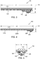
- a side view of the first example linear light fixture 100 is shown in FIG. 3 .
- the first example linear light fixture 100 has a length "L1" and a height "H1" - both greater than 0 units of measurement, but not equal to each other.
- the first example linear light fixture can be low profile and have a height HI that is approximately less than 5 inches (e.g., 4 inches) and a length L1 that is approximately 20-27 inches (e.g. a two-foot version).
- a side view of the second example linear light fixture 200 is shown in FIG. 4 .
- the second example linear light fixture 200 has a length "L2" and a height "H2" - both greater than 0 units of measurement, but not equal to each other.
- the second example linear light fixture can be low profile and have a height H2 that is approximately 4 inches and a length L2 that is approximately 44.5 inches (e.g. a four foot version).
- FIG. 5 shows an end view of the first example linear light fixture 100 having a width "W" that is approximately 6.5 inches.
- the specific dimensions provided herein are example dimensions.
- the first example linear light fixture 100 and the second example linear light fixture 200 can have different dimensions, such as other lengths, heights, and widths, including dimensions not explicitly provided herein.
- the dimensions of the linear light fixture may be chosen based at least in part on space requirements or limitations of a particular location where the linear light fixture is to be installed and/or used.
- the housing body 110 extends the length L1 of the first example linear light fixture 100.
- the bezel 120 and the driver housing 150 are attached to the housing body 110.
- the driver housing 150 is arranged linearly adjacent to the bezel 120 such that the first example linear light fixture 100 has a low profile corresponding to the height HI.
- the longer housing body 210 extends the length L2 of the second example linear light fixture 200.
- the first bezel 220a, the second bezel 220b, and the driver housing 250, including the driver housing cover 260 are attached to the longer housing body 210.
- the driver housing 250 is arranged linearly adjacent to the first bezel 220a and the second bezel 220b such that the second example linear light fixture 200 has a low profile corresponding to the height H2.
- the linear light fixtures of the present application with the light source and the driver and/or battery backup components arranged linearly adjacent to each other are comparatively smaller in height and are, therefore, low profile.
- the first example linear light fixture 100 has a compact width corresponding to the width W.
- Power connection ports 184 can be included on the driver housing 150 to provide access for electrical cables or wires into the driver housing 150 to supply electrical power to the driver 155.
- the power connection ports 184 can also provide access for electrical cables or wires out of the driver housing 150 to supply electrical power to, for example, another nearby linear light fixture such as a loop in/loop out wiring configuration.
- the linear light fixtures 100, 200 may also provide for through-feed wiring.
- power wiring may be passed through ports 184 through the entirety of the fixtures 100, 200, and received by a nearby fixture from an opposite end. It is understood that such through-feed wiring is not intended to be limited to power wiring, or port 184.
- the integrally extruded conduit 170 can carry wires from an external power source as well as from an internal power source.
- a plug 185 can be threaded into the power connection port 184 to seal the port in instances, for example, where electrical access through one or more of the power connection ports 184 is not needed.
- the linear light fixture 100 includes the housing body 110 to which the bezel 120 is configured to attach.
- the housing body 110 can include a plurality of threaded bores 113 into which a plurality of fasteners 111 (e.g. bolts or screws) can be threaded to secure the bezel 120 to the housing body 110.
- the bezel can also include a plurality of threaded or non-threaded apertures 114 through which the plurality of fasteners 111 extend to secure the bezel 120 to the housing body.
- a plurality of corresponding locking or non-locking washers 112 can be placed between the bezel 120 and each of the plurality of fasteners 111 at each of the plurality of threaded or non-threaded apertures 114 to provide a surface against which each of the plurality of fasteners 111 can contact when the bezel 120 is secured to the housing body 110.
- the housing body 110 can include a lighting compartment 320 into which the LEDs 125 can be arranged.
- the lighting compartment 320 can be, for example, machined into a front surface 115 of the housing body 110 and can correspond at least in part to a size or shape of the LEDs 125 such that the LEDs 125 can be placed into the lighting compartment 320.
- the lighting compartment 320 can be machined to have a depth from the front surface 115 of the housing body 110 such that when the LEDs 125 are placed into the lighting compartment 320, the LEDs are at or below a plane coplanar with the front surface 115 of the housing body 110.
- the lighting compartment 320 can be machined to have a depth from the front surface 115 of the housing body 110 such that when the LEDs 125 are placed into the lighting compartment 320, the LEDs are above a plane coplanar with the front surface 115 of the housing body 110.
- Each light emitting diode can be wired (e.g. as a string of light emitting diodes) onto one or more printed circuit boards (PCB) to form the LEDs 125.
- a reflector 126 can be mounted in proximity to the LEDs 125 to project, deflect, reflect, or otherwise distribute light produced by the LEDs 125 in one or more of a given direction or at one or more of a predetermined angle.
- the reflector 126 can be secured to the housing body 110 within the lighting compartment 320 by bolts, screws, clips, or any other fastener. Similar to the placement of the LEDs 125 within the lighting compartment 320, the reflector 126 can also be arranged at or below a plane coplanar with the front surface 115 of the housing body 110 or above a plane coplanar with the front surface 115 of the housing body 110.
- a gasket groove 325 can be machined around a periphery of the lighting compartment 320.
- the gasket groove 325 can be configured to receive a seal gasket 131 that is made of a material, such as rubber, that is flexible and that permits compressibility.
- the lens 130 can be pressed against the gasket 131, a lens protector 132 can be placed between the lens 130 and the bezel 120, and the bezel 120 can then be secured to the housing body 110 with the plurality of fasteners 111.
- the bezel 120 in combination with the lens 130 and the gasket 131 can thus provide a water-tight as well as a dust-tight enclosure around the LEDs 125 to protect the LEDs 125 and any associated wiring or electrical components from particulates, moisture, and any other unwanted debris or contaminants.
- the driver housing 150 can include a seal or gasket 151 configured to correspond to a shape of the outer periphery of the driver housing 150 to provide a water-tight as well as a dust-tight enclosure around the driver 155 and/or battery backup components to protect the driver 155 and/or battery backup components and any associated wiring or electrical components from particulates, moisture, and any other unwanted debris or contaminants.
- the gasket 151 can be arranged directly on the front surface 115 of the housing body 110 or can be arranged within a groove machined into the front surface 115 of the housing body 110 or a groove machined into an adjoining surface of the driver housing 150.
- the driver housing 150 is secured to the housing body 110 with the plurality of fasteners 111.
- the driver 155 is an electronics module that is configured to convert alternating current (A/C) to direct current (D/C) or direct current (D/C) to direct current (D/C) and that is used to power the LEDs 125.
- the driver 155 and/or battery backup components can be secured to the housing body 110 with a bracket 156 and one or more fasteners.
- the driver housing cover 160 can attach to the driver housing 150 via a threaded connection provided at an access port 153 in the driver housing 150.
- the driver housing cover 160 can include a seal or gasket 152 configured to correspond to a shape of the driver housing cover 160 to provide a water-tight as well as a dust-tight seal around the access port 153 to protect the driver 155 and/or battery backup components and any associated wiring or electrical components from particulates, moisture, and any other unwanted debris or contaminants.
- the driver housing cover 160 is removable from the driver housing 150 such that a user can access the fixture wiring interface to connect wires to the driver via the access port 153 without having to remove the plurality of fasteners 111 that secure the driver housing 150 to the housing body 110.
- the access port 153 can provide access from a front of the linear light fixture 100 when a back of the light fixture is mounted to a surface, such as a wall or a ceiling.
- the access port 153 can also provide a user access to the driver 155 and/or battery backup components and any associated wiring or electrical components during initial installation of the light fixture (e.g. to connect a main power line to the light fixture), during routine inspections of the light fixtures, as well as during any other service or maintenance operations.
- the driver housing 150 and the plurality of fasteners 111 can be removed.
- the LEDs 125 and any associated wiring or electrical components are housed separately from the driver 155 and/or battery backup components and any associated wiring or electrical components.
- the linear light fixture 100 is therefore configured to be explosion proof and able to withstand internal pressures (e.g. pressures originating from the LEDs 125 and any associated wiring or electrical components or the driver 155 and/or battery backup components and any associated wiring or electrical components) or external pressures (e.g. pressures originating from the environment in which the linear light fixture 100 is employed).
- the linear light fixture 100 can therefore be used in hazardous or harsh locations and is configured to comply with the requirements of, for example, Class 1, Div. 1, NEC (e.g. explosive gas) and Class 2, Div. 1, NEC (e.g. explosive dust).
- the driver 155 and/or battery backup components and the driver housing 150 can be configured to contain or withstand exposure to pressures (e.g. hydrostatic pressures) of approximately 600 psia and the lens can be configured to contain or withstand exposure to pressures (e.g. hydrostatic pressures) of approximately 300 psia.
- the driver 155 and/or battery backup components and the driver housing 150, including the driver housing cover 160 can be configured to contain or withstand exposure to pressures (e.g. hydrostatic pressures) that are greater than or less than approximately 600 psia and the lens can be configured to contain or withstand exposure to pressures (e.g. hydrostatic pressures) that are greater than or less than approximately 300 psia.
- the linear light fixture 100 is configured to arrest ignition of gas (e.g. from hot to cold) such that, if any internal electrical ark, spark, ignition, or explosion were to occur within the housing body, the gas, flame, or other element heated as a result of the internal electrical ark, spark, ignition, or explosion would be contained within and would be arrested (e.g. extinguished) within the sealed lighting compartment 320 or the sealed driver housing 150 and would not come into contact with the environment.
- gas e.g. from hot to cold
- the gas, flame, or other element heated as a result of the internal electrical ark, spark, ignition, or explosion would be contained within and would be arrested (e.g. extinguished) within the sealed lighting compartment 320 or the sealed driver housing 150 and would not come into contact with the environment.
- the linear light fixture 100 is designed such that in the event any gas, flame, or other element heated as a result of the internal electrical ark, spark, ignition, or explosion manages to escape from the enclosure, such gas, flame, or other element would have a temperature insufficient to ignite a gas or other particulate in the environment in which the linear light fixture 100 is employed.
- the housing body 110 including the lighting compartment 320, the gasket groove 325, and the gasket 131 as well as the lens 130 and the bezel 120 are configured to provide a sealed enclosure around the LEDs 125 that arrests any ignition of gas.
- the housing body 110, the driver housing 150 and the gasket 151, as well as the driver housing cover 160 and the gasket 152 are configured to provide a sealed enclosure around the driver 155 and/or battery backup components that arrests any ignition of gas.
- the front surface 115 of the housing body 110 is extruded or machined to be flat or planar.
- the mating surfaces of the driver housing 150 and the bezel 120 are also machined to be flat or planar. Therefore, when mounted together, these flat or planar mating surfaces provide a uniformly tight interface between the front surface 115 of the housing body and the corresponding mating surfaces of the driver housing 150 and the bezel 120 such that any gas, flame, or other ignition source is arrested (e.g. prevented) from leaking out of or exiting the sealed compartments within the driver housing 150 and within the lighting compartment 320 behind the lens 130.
- the housing body 110 can be formed as a single housing, for example, using an extrusion process.
- a single housing is to be understood, therefore, as a component (e.g. a metallic component extruded out of aluminum alloy) that has integral features formed therein.
- the housing body 110 can be extruded and subsequently machined.
- Such a process provides a housing body 110 that is a single piece part including integral structural features that are structurally rigid and capable of withstanding the aforementioned temperatures and pressures to which the linear light fixture 100 may be exposed when employed in hazardous or harsh locations.
- the housing body 110 can include at least one integrally extruded conduit 170 (e.g. wire way) in which at least one wire can be placed.
- the integrally extruded conduit 170 can extend from one end of the linear light fixture 100 to another end of the linear light fixture, for example, along the length L1 of the linear light fixture 100.
- One or more set screws 175 e.g. M10 set screws
- the integrally extruded conduit 170 can be accessed from the front surface 115 of the housing body via one or more access wells or pockets (e.g. cavities or apertures) that are machined into the housing body 110.
- a lighting access pocket 310 can be machined into the lighting compartment 320 to provide access to the integrally extruded conduit 170 at a location proximate to the LEDs 125 and any associated wiring or electrical components.
- a driver access pocket 305 can be machined into the housing body 110 at a location underneath the driver housing 150 to provide access to the integrally extruded conduit 170 at a location proximate to the driver 155 and/or battery backup components and any associated wiring or electrical components.
- a lighting pocket cap or plug 311 can be inserted into the lighting access pocket 310, and a driver pocket cap or plug 306 can be inserted into the drive access pocket 305, to provide (e.g.
- a ground wire 158 can be electrically connected to the housing body 110 and to ground (not shown) to provide a conducting path that directs any unwanted electrical current or charge away from the linear light fixture 100 and into ground, independent of the normal current-carrying path.
- the linear light fixture 100 is shown with various mounting hardware attached thereto.
- the linear light fixture 100 includes an integral mounting flange 405 formed on a back surface 116 of the linear light fixture 100.
- the integral mounting flange 405 can be extruded as part of the housing body 110 and can include a first side 410 and a second side 415 configured to provide a structure onto which various mounting hardware can attach.
- the integral mounting flange 405 can be configured to provide a universal mounting system that accepts a wide range of bracket configurations such that the linear light fixture 100 can interchangeably connect to a variety of mounting hardware, including the specific mounting hardware disclosed herein as well as additional mounting hardware not disclosed herein. For example, as shown in FIG.
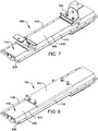
- a swivel mount 505 can be attached to the integral mounting flange 405.
- a back mount 510 can be attached to the integral mounting flange 405.
- a bracket mount 515 can be attached to the integral mounting flange 405, as shown in FIG. 9
- a pole mount 520 can be attached to the integral mounting flange 405, as shown in FIG. 10 .
- an integral eyelet 525 can be machined into the housing body 110 to serve as a secondary retention point or redundant safety connection.
- one end of one or more safety cables or lanyards can be attached to or through the integral eyelet 525 and another end of the cables can be secured to a structure onto which the linear light fixture 100 and the mounting hardware are attached, such as a wall or ceiling.
- the mounting hardware comes loose (e.g. due to vibration, shock, or contact) or breaks and fails to securely attach the linear light fixture 100 to the structure, the cable will hold the linear light fixture 100 in proximity to the structure at a length of the cable.
- the linear light fixture 100 will not fall onto a person or object causing injury to the person or object and or damage to the linear light fixture 100.
- Multiple integral eyelets 525 can be machined into the housing body 110, for example at each corner of the housing body 110, to provide additional redundant safety connections.
- the first example linear light fixture 100 and the second example linear light fixture 200 are shown, respectively, with their respective driver housings 150, 250 and their respective bezels 120, 220a, 220b and lens 130, 230 removed for clarity.
- the driver access pocket 305 is located in proximity to the driver 155 and/or battery backup components to provide an opening in the front surface 115 of the housing body 110 to permit access to the integrally extruded conduit 170.
- the lighting access pocket 310 formed in the lighting compartment 320, is located in proximity to the LEDs 125 to provide another opening in the front surface 115 of the housing body 110 to permit access to the integrally extruded conduit 170.
- the driver pocket plug 306 and the lighting pocket plug 311 are optionally and respectively placed.
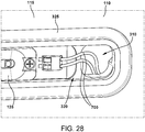
- the driver 155 and/or battery backup components is electrically connected to the LEDs 125 via at least one wire (e.g. wire 700 shown in FIG. 28 ) that runs through the integrally extruded conduit 170 between the driver 155 and/or battery backup components, and the LEDs 125.
- the wire connects to terminals of the driver 155 and/or battery backup components at the driver access pocket 305 and connects to the LEDs 125 at the lighting access pocket 310.
- a first driver access pocket 305a and a second driver access pocket 305b are located in proximity to a driver 255 and/or battery backup components to provide two openings in a front surface 215 of the longer housing body 210 to respectively permit access to a first integrally extruded conduit 170a and a second integrally extruded conduit 170b (shown in FIGs. 15 , 17, and 18 ).
- a first lighting access pocket 310a formed in a first lighting compartment 320a, is located in proximity to first LEDs 225a to provide another opening in the front surface 215 of the longer housing body 210 to permit access to the first integrally extruded conduit 170a.
- a second lighting access pocket 310b formed in a second lighting compartment 320b, is located in proximity to second LEDs 225b to provide yet another opening in the front surface 215 of the longer housing body 210 to permit access to the second integrally extruded conduit 170b.
- first and second driver pocket plugs 306a, 306b and first and second lighting pocket plugs 311a, 311b are respectively placed.
- the driver 255 and/or battery backup components is electrically connected to the first and second LEDs 225a, 225b via wires (e.g. wires 701, 702 shown in FIG.
- the wires connect to terminals of the driver 255 and/or battery backup components at the first and second driver access pockets 305a, 305b and connect to the first and second LEDs 225a, 225b at the first and second lighting access pockets 310a, 310b.
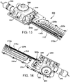
- FIGS. 13 and 14 A cutaway perspective view of the second example linear light fixture 200, with an alternate wiring configuration, is shown in FIGS. 13 and 14 .
- wires 701 are connected to the driver 255 and/or battery backup components and the first LEDs 225 and run through the first integrally extruded conduit 170a from the first driver access pocket 305a to the first lighting access pocket 310a.
- the integrally extruded conduit 170 completely encloses or encapsulates the wires 701 and is formed as an integral wire way or path within the longer housing body 210.
- a power supply (e.g. cable gland or fitting) 280 is shown attached (e.g. threaded) to the driver housing 250 and electrically connect to the driver to provide electrical power (e.g. alternating current) to the driver 255.
- the first example linear light fixture 100 is shown with the lighting compartment 320 formed in the front surface 115 of the housing body 110.
- the first and second integrally extruded conduits 170a, 170b are shown running the length of the housing body 110 from one end to another.
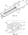
- a close-up view of the lighting access pocket 310 is shown in FIG. 16 .
- the lighting access pocket 310 is formed in the lighting compartment 320 internal to the gasket groove 325 and provides access from the front surface 115 of the housing body 110 to the first integrally extruded conduit 170a.
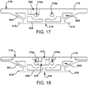
- FIG. 17 shows a cross-sectional view taken along line 17-17, including the driver access pocket 305
- FIG. 18 shows a cross-sectional view taken along line 18-18, including the lighting access pocket 310.
- the driver access pocket 305 is formed in the housing body 110 to provide access from the front surface 115 of the housing body 110 to the first integrally extruded conduit 170a.
- the second integrally extruded conduit 170b remains closed; however in other example embodiments, for example, where more LEDs are included and additional access to the driver or the LEDs is needed, another driver access pocket can be included provide access to the second integrally extruded conduit 170b.
- the integral mounting flange 405 including the first side 410 and the second side 415 is also provided on the back surface 116 of the housing body 110.
- voids, hollows, or spaces 600 can be formed in the housing body 110 during the extrusion process or machined subsequent to the extrusion process to remove material and reduce a weight of the light fixture or to provide reinforced structural support members 601 on the housing body 110.
- the lighting access pocket 310 in FIG. 18 it can be seen that the in order to provide access from the front surface 115 of the housing body 110 to the first integrally extruded conduit 170a, the lighting access pocket 310 can include a side step portion 315 (e.g. machined using a side cutter or other tool) that extends horizontally through the housing body 110.
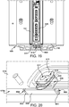
- FIGS. 19 and 20 a cutaway perspective view of the lighting access pocket 310 is provided, showing a potting compound 800 (e.g. an epoxy or sealant) in the lighting access pocket 310.
- the potting compound 800 can isolate or seal the first integrally extruded conduit 170a at the opening formed in the housing body 110 by the lighting access pocket 310.
- the lighting pocket plug 311 extends across the opening of the lighting access pocket 310 and includes a first and second wire aperture 312, 313 through which wires (e.g. a positive connection and a neutral connection) can be fed or inserted and held or separated from each other by the lighting pocket plug 311.
- the lighting pocket plug 311 can include a potting aperture 317 into which a tip or nozzle of a potting tool can be inserted.
- the potting aperture 317 is configured to form a mating connection around the tip or nozzle of the potting tool such that the potting compound 800 can be injected into the lighting access pocket 310 through the potting aperture 317 in a sealed or pressurized manner.
- a first and second wire grommet 801, 802 can be placed within the first integrally extruded conduit 170a at a distance from each other to control a flow of the potting compound 800 within the first integrally extruded conduit 170a when the potting compound 800 is injected into the lighting access pocket 310 through the potting aperture 317 formed in the lighting pocket plug 311.
- Each of the first and second wire grommets 801, 802 can include a corresponding wire aperture 803, 804, respectively through which a wire can extend.
- the lighting pocket plug 311 as well as the first and second wire grommets 801, 802 can be formed of a foam elastomer or other resilient material by which each can be press-fitted into a corresponding opening of lighting access pocket 310 or the first integrally extruded conduit 170a. It is to be understood that, while the potting compound 800 and method of injecting the potting compound 800 is described with respect to the lighting access pocket 310, other holes, apertures, and conduits formed within the housing body or other element of the linear lighting fixture can also benefit from the same or similar potting technique to seal and/or isolate the hole, aperture, or conduit from exposing or exposure to various environments. For example, gas compartment isolation prevents explosion pressure piling and reduces pressure level.
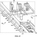
- FIG. 21 illustrates a first potting 805 provided in the driver access pocket 305 and the first integrally extruded conduit 170a between the driver pocket plug 306 and first and second first potting grommets 806, 807.
- a second potting 810 is provided in the lighting access pocket 310 and the first integrally extruded conduit 170a between the lighting pocket plug 311 and first and second potting grommets 811, 812.
- At least one wire 700 is sealed by the first and second pottings 805, 810 and extends in the first integrally extruded conduit 170a between the driver 155 and/or battery backup components and the LEDs 125.
- the wire 700 is therefore isolated and sealed within the housing body 110 as well as within the driver housing and behind the lens and bezel such that the linear light fixture 100 can be employed in harsh and hazardous locations.
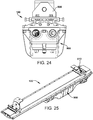
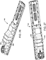
- FIGS. 22-27 illustrate the first example linear light fixture 100 with a battery backup unit 900 attached thereto.
- the battery backup unit 900 is configured to provide auxiliary power to the driver to power the LEDs in the event main power to the linear light fixture 100 is disrupted (e.g. during an electrical outage).
- the back mount 510 is attached to the linear light fixture 100 to secure the light fixture, including the battery backup unit 900, to a structure, such as a wall or a ceiling.
- the swivel mount 505 is attached to the linear light fixture 100 to secure the light fixture, including the battery backup unit 900, to a structure, such as a wall or a ceiling.
- the battery backup unit 900 can include a battery backup housing 905 that encloses a battery and the driver (neither of which is shown, but both of which are understood to be located inside the battery backup housing 905).
- FIGS. 28-31 illustrate additional wiring configurations of the example linear light fixtures disclosed herein.
- the lighting access pocket 310 is machined in the lighting compartment 320 internal to the gasket groove 325.
- the lighting access pocket 310 provides access from the front surface 115 of the housing body 110 to the integrally extruded conduit such that at least one wire 700 can connect from the driver (not shown) to the LEDs 125.
- FIG. 29 shows the first and second driver access pockets 305a, 305b machined in the front surface 215 of the longer housing body 210 with first and second wires 701, 702 extending therefrom.
- the first wire 701 runs through the longer housing body 210 (within the integrally extruded conduit) and emerges in the first lighting compartment 320a from the first lighting access pocket 310a to connect to the first LEDs 225a.
- FIG. 30 shows the first and second driver access pockets 305a, 305b with corresponding potting 820, 825 injected into the respective openings to seal around the first and second wires 701, 702. As shown, driver or lighting pocket caps or plugs are optional and are not inserted into the respective access pockets shown in FIG. 30 .
- FIG. 31 shows the first and second wires 701, 702 connected to the driver 255. In. FIG. 31 , the potting has not been injected into the corresponding first and second driver access pockets 305a, 305b.
Landscapes
- Engineering & Computer Science (AREA)
- General Engineering & Computer Science (AREA)
- Microelectronics & Electronic Packaging (AREA)
- Physics & Mathematics (AREA)
- Optics & Photonics (AREA)
- Non-Portable Lighting Devices Or Systems Thereof (AREA)
- Arrangement Of Elements, Cooling, Sealing, Or The Like Of Lighting Devices (AREA)
- Architecture (AREA)
Claims (13)
- Appareil d'éclairage linéaire (100), comprenant :un corps de boîtier (110), le corps de boîtier (110) comportant au moins un conduit entièrement extrudé (170) et un compartiment d'éclairage (320),au moins une diode émettant de la lumière (125) placée dans le compartiment d'éclairage (320),une source d'alimentation fixée au corps de boîtier (110) et configurée pour fournir de la puissance électrique à ladite au moins une diode émettant de la lumière (125), etau moins un fil (700) connectant électriquement la source d'alimentation à ladite au moins une diode émettant de la lumière (125) dans lequel ledit au moins un fil (700) est disposé dans le conduit entièrement extrudé (170) ;une poche d'accès (305, 310) dans le corps de boîtier (110) dans lequel le conduit entièrement extrudé (170) peut être accédé depuis une surface avant (115) du corps de boîtier (110) via la poche d'accès (305, 310), caractérisé en ce quele conduit entièrement extrudé (170) est scellé et que le compartiment d'éclairage (320) est configuré pour fournir une enceinte scellée autour d'au moins une diode émettant de la lumière (125) pour créer une enceinte à l'épreuve des explosions.
- Appareil d'éclairage linéaire (100) selon la revendication 1, dans lequel la source d'alimentation comprend un convertisseur de puissance et/ou un dispositif de stockage d'énergie et/ou une batterie de secours, de préférence agencés linéairement adjacents à ladite au moins une diode émettant de la lumière.
- Appareil d'éclairage linéaire (100) selon la revendication 1, dans lequel la poche d'accès (305, 310) dans le corps de boîtier comporte une poche d'accès de circuit de commande (305) située à proximité d'un circuit de commande (155) et/ou de composants de batterie de secours et une poche d'accès d'éclairage (310) située à proximité de ladite au moins une diode émettant de la lumière (125), et dans lequel ledit au moins un fil (700) s'étend à travers le conduit entièrement extrudé (170) entre la poche d'accès de circuit de commande (305) et la poche d'accès d'éclairage (310).
- Appareil d'éclairage linéaire (100) selon la revendication 2, comprenant en outre une lentille (130) incluant ladite au moins une diode émettant de la lumière (125) et une poche d'accès d'éclairage (310) et un boîtier de circuit de commande (150) incluant le convertisseur de puissance (155) et/ou le dispositif de stockage d'énergie, et une poche d'accès de circuit de commande (305).
- Appareil d'éclairage linéaire (100) selon la revendication 3 ou 4, comprenant en outre un composé de remplissage (800) disposé dans au moins une poche parmi la poche d'accès de circuit de commande (305) et la poche d'accès d'éclairage (310).
- Appareil d'éclairage linéaire (100) selon la revendication 5, comprenant en outre un passe-câble (801, 802) agencé dans le conduit entièrement extrudé (170) et configuré pour contrôler un flux du composé de remplissage (800).
- Appareil d'éclairage linéaire (100) selon la revendication 1, dans lequel la poche d'accès est scellée pour former une partie de l'enceinte à l'épreuve des explosions.
- Appareil d'éclairage linéaire (100) selon la revendication 1, dans lequel ledit au moins un fil (700) entre dans l'appareil d'éclairage au niveau d'une première extrémité et sort de l'appareil d'éclairage au niveau d'une deuxième extrémité opposée à la première extrémité.
- Appareil d'éclairage linéaire (100) selon la revendication 1, dans lequel le conduit entièrement extrudé (170) s'étend dans toute la longueur du corps de boîtier (110).
- Appareil d'éclairage linéaire (100) selon la revendication 9, comprenant en outre un composé de remplissage (800) dans le conduit entièrement extrudé (170), le composé de remplissage (800) étant configuré pour sceller au moins une partie du conduit entièrement extrudé (170).
- Appareil d'éclairage linéaire (100) selon la revendication 1, dans lequel le corps de boîtier (110) est extrudé et comprend en outre au moins un oeillet (525).
- Appareil d'éclairage linéaire (100) selon la revendication 11, dans lequel l'appareil d'éclairage est fixé à une structure au moins en partie via un câble ou un cordon attaché audit, ou au travers dudit, au moins un oeillet (525) au niveau d'une première extrémité et attaché à la structure au niveau d'une deuxième extrémité.
- Procédé de fabrication de l'appareil d'éclairage (100) selon l'une quelconque des revendications précédentes, comprenant les étapes suivantes :la formation du corps de boîtier (110) sous forme d'un élément unique en utilisant un traitement d'extrusion ; etla formation d'éléments entièrement extrudés dans le corps de boîtier (110), dans lequel au moins un des éléments entièrement extrudés est le conduit entièrement extrudé (170) dans lequel ledit au moins un fil (700) peut être disposé, le conduit entièrement extrudé (170) s'étendant le long de la longueur de l'appareil d'éclairage (100).
Applications Claiming Priority (2)
| Application Number | Priority Date | Filing Date | Title |
|---|---|---|---|
| US201562170886P | 2015-06-04 | 2015-06-04 | |
| PCT/US2016/035635 WO2016196876A1 (fr) | 2015-06-04 | 2016-06-03 | Luminaire à del linéaire utilisable dans des lieux hostiles et dangereux |
Publications (3)
| Publication Number | Publication Date |
|---|---|
| EP3303909A1 EP3303909A1 (fr) | 2018-04-11 |
| EP3303909A4 EP3303909A4 (fr) | 2018-12-12 |
| EP3303909B1 true EP3303909B1 (fr) | 2020-07-29 |
Family
ID=57441856
Family Applications (1)
| Application Number | Title | Priority Date | Filing Date |
|---|---|---|---|
| EP16804488.1A Active EP3303909B1 (fr) | 2015-06-04 | 2016-06-03 | Luminaire à del linéaire utilisable dans des lieux hostiles et dangereux |
Country Status (5)
| Country | Link |
|---|---|
| US (1) | US9976735B2 (fr) |
| EP (1) | EP3303909B1 (fr) |
| CA (1) | CA2987062C (fr) |
| MX (1) | MX370878B (fr) |
| WO (1) | WO2016196876A1 (fr) |
Families Citing this family (29)
| Publication number | Priority date | Publication date | Assignee | Title |
|---|---|---|---|---|
| US10502376B2 (en) * | 2015-05-01 | 2019-12-10 | Hubbell Incorporated | Luminaire with independently controlled light output |
| WO2017156233A1 (fr) | 2016-03-10 | 2017-09-14 | Cooper Technologies Company | Enceinte antidéflagrante ayant des moyens de maintien et de protection de trajectoire de flamme |
| USD841860S1 (en) * | 2016-05-03 | 2019-02-26 | Eaton Intelligent Power Limited | Light fixture with battery backup |
| US10578262B2 (en) * | 2016-12-21 | 2020-03-03 | Orion Energy Svstems, Inc. | Systems and methods for retrofitting light fixtures |
| BE1025411B1 (fr) * | 2017-07-19 | 2019-02-18 | Schreder S.A. | Tête de luminaire modulaire |
| WO2019028222A1 (fr) * | 2017-08-02 | 2019-02-07 | Multi Radiance Medical | Système et procédé pour diriger la lumière dans l'œil d'un patient |
| US11638833B2 (en) | 2017-08-02 | 2023-05-02 | Multi Radiance Medical | Reducing light polution in photobiomodulation therapy of a patients eye |
| DE102017128620B4 (de) * | 2017-12-01 | 2023-03-23 | Eaton Protection Systems Ip Gmbh & Co. Kg | Modulare LED-Leuchte |
| CN107965713A (zh) * | 2017-12-06 | 2018-04-27 | 南京京泽照明科技有限公司 | 一种线性隔爆型防爆灯 |
| CN112368895B (zh) * | 2018-06-28 | 2022-08-26 | 昕诺飞控股有限公司 | 包括电缆压盖、电线传输元件和外壳的成套部件、由该成套部件制成的系统以及功能性连接该系统的方法 |
| USD928350S1 (en) * | 2019-01-25 | 2021-08-17 | Eaton Intelligent Power Limited | Luminaire |
| USD939126S1 (en) * | 2019-02-14 | 2021-12-21 | Appleton Grp Llc | Linear LED fixture |
| CA3082576C (fr) | 2019-06-07 | 2023-09-12 | Abl Ip Holding Llc | Luminaire lineaire |
| USD929015S1 (en) | 2019-06-07 | 2021-08-24 | Abl Ip Holding Llc | Lighting fixture |
| USD934806S1 (en) * | 2019-06-19 | 2021-11-02 | Appleton Grp Llc | Linear LED series emergency battery backup luminaire |
| US11022260B2 (en) * | 2019-09-25 | 2021-06-01 | Xiamen Eco Lighting Co. Ltd. | Lighting apparatus with a light module with elongated housing and a base bracket holding the elongated housing |
| USD954332S1 (en) * | 2019-12-27 | 2022-06-07 | Eaton Intelligent Power Limited | LED light fixture |
| CN113063104A (zh) | 2019-12-31 | 2021-07-02 | 伊顿智能动力有限公司 | 不使用散热器的热管理危险场所led灯具、组件和方法 |
| USD935065S1 (en) * | 2020-01-03 | 2021-11-02 | Appleton Grp LLP | Explosion proof emergency linear LED lighting fixture |
| USD935064S1 (en) * | 2020-01-03 | 2021-11-02 | Appleton Grp Llc | Explosion proof standard linear LED lighting fixture |
| US10941932B1 (en) | 2020-05-18 | 2021-03-09 | Abl Ip Holding Llc | Water-resistant extruded housing for emergency lighting component |
| WO2022155218A1 (fr) * | 2021-01-12 | 2022-07-21 | Hubbell Incorporated | Optique protégée contre une flamme |
| CA3207863A1 (fr) | 2021-01-12 | 2022-07-21 | Hubbell Incorporated | Luminaire protege contre les explosions |
| DE202021100555U1 (de) | 2021-02-04 | 2022-05-05 | Zumtobel Lighting Gmbh | Leuchte mit Aufhängungsbügel |
| CN215061673U (zh) * | 2021-04-30 | 2021-12-07 | 伊顿智能动力有限公司 | Led防爆灯具 |
| USD1039209S1 (en) * | 2021-04-30 | 2024-08-13 | Eaton Intelligent Power Limited | Support mount for mounting luminaire assembly |
| WO2023055977A1 (fr) | 2021-10-01 | 2023-04-06 | Hubbell Incorporated | Système d'identification pour raccord de sol encastré |
| US12276412B2 (en) | 2021-10-01 | 2025-04-15 | Hubbell Incorporated | Flame protected optic |
| IT202400004420A1 (it) * | 2024-02-29 | 2025-08-29 | Roj S R L | Porgitrama per telai di tessitura comprendente un gruppo ottico indipendente, integrato nel gruppo elettromagnete di rilascio del filo di trama |
Family Cites Families (19)
| Publication number | Priority date | Publication date | Assignee | Title |
|---|---|---|---|---|
| EP1711739A4 (fr) | 2004-01-28 | 2008-07-23 | Tir Technology Lp | Luminaire directement visible |
| US7165863B1 (en) * | 2004-09-23 | 2007-01-23 | Pricilla G. Thomas | Illumination system |
| US7513639B2 (en) * | 2006-09-29 | 2009-04-07 | Pyroswift Holding Co., Limited | LED illumination apparatus |
| US9212812B2 (en) * | 2013-02-11 | 2015-12-15 | Cree, Inc. | LED light fixture with integrated light shielding |
| US8414144B2 (en) * | 2008-02-28 | 2013-04-09 | University Of Central Florida Research Foundation, Inc. | Quick change lamp ballast assembly |
| CN101571237B (zh) * | 2008-04-30 | 2013-05-08 | 奥斯兰姆有限公司 | 发光二极管模块及包括该发光二极管模块的灯串 |
| CA2736395C (fr) * | 2008-09-15 | 2017-03-07 | Led Roadway Lighting Ltd. | Dispositif d'eclairage routier a diodes electroluminescentes (del) |
| US20100302790A1 (en) * | 2009-05-27 | 2010-12-02 | Etronic Team Co., Ltd. | Led luminaire and method for fabricating the same |
| US20110089390A1 (en) * | 2009-10-16 | 2011-04-21 | Steinkraus Thomas F | Post mount for lighted handrail assembly |
| US9377173B2 (en) * | 2010-04-21 | 2016-06-28 | Cooper Technologies Company | LED luminaire assembly |
| US8616720B2 (en) * | 2010-04-27 | 2013-12-31 | Cooper Technologies Company | Linkable linear light emitting diode system |
| US8888315B2 (en) * | 2011-03-07 | 2014-11-18 | Greendot Technologies, Llc | Vapor-tight lighting fixture |
| US10823347B2 (en) | 2011-07-24 | 2020-11-03 | Ideal Industries Lighting Llc | Modular indirect suspended/ceiling mount fixture |
| US9995444B2 (en) * | 2011-10-17 | 2018-06-12 | Ecosense Lighting Inc. | Linear LED light housing |
| GB2497282A (en) * | 2011-12-02 | 2013-06-12 | Marshalls Mono Ltd | External lanterns and method of manufacture |
| US9192008B2 (en) * | 2012-03-26 | 2015-11-17 | B/E Aerospace, Inc. | Reduced-size modular LED washlight component |
| DE102012023989A1 (de) * | 2012-12-06 | 2014-06-12 | Cooper Crouse-Hinds Gmbh | Explosionsgeschützte Leuchte |
| US20140313780A1 (en) * | 2013-04-17 | 2014-10-23 | Pixi Lighting, Inc. | Field-serviceable flat panel lighting device |
| US9546781B2 (en) * | 2013-04-17 | 2017-01-17 | Ever Venture Solutions, Inc. | Field-serviceable flat panel lighting device |
-
2016
- 2016-06-03 WO PCT/US2016/035635 patent/WO2016196876A1/fr not_active Ceased
- 2016-06-03 EP EP16804488.1A patent/EP3303909B1/fr active Active
- 2016-06-03 CA CA2987062A patent/CA2987062C/fr active Active
- 2016-06-03 US US15/172,225 patent/US9976735B2/en active Active
- 2016-06-03 MX MX2017015487A patent/MX370878B/es active IP Right Grant
Non-Patent Citations (1)
| Title |
|---|
| None * |
Also Published As
| Publication number | Publication date |
|---|---|
| EP3303909A1 (fr) | 2018-04-11 |
| EP3303909A4 (fr) | 2018-12-12 |
| MX2017015487A (es) | 2018-02-19 |
| CA2987062C (fr) | 2023-08-15 |
| WO2016196876A1 (fr) | 2016-12-08 |
| US9976735B2 (en) | 2018-05-22 |
| MX370878B (es) | 2020-01-08 |
| CA2987062A1 (fr) | 2016-12-08 |
| US20160356475A1 (en) | 2016-12-08 |
Similar Documents
| Publication | Publication Date | Title |
|---|---|---|
| EP3303909B1 (fr) | Luminaire à del linéaire utilisable dans des lieux hostiles et dangereux | |
| US10584831B2 (en) | Luminaire for use in harsh and hazardous locations | |
| US11617254B2 (en) | Solid state lighting fixtures | |
| US11112104B2 (en) | Relating to light-emitting diode modules | |
| US10415803B2 (en) | Surface mounted light fixture and heat dissipating structure for same | |
| CA3082576C (fr) | Luminaire lineaire | |
| US11686440B2 (en) | LED lighting fixture | |
| US8764219B2 (en) | Sealed LED light fixture for use in food processing applications | |
| US7033038B2 (en) | In-grade light fixture housing and hydrological barrier plate for use therein | |
| US12078306B2 (en) | Linear LED luminaire housing for use in harsh and hazardous locations | |
| KR200485418Y1 (ko) | 작업등기구 | |
| CN107949744A (zh) | 用于有害环境的气密密封的照明器具 | |
| WO2021154984A1 (fr) | Dispositif d'éclairage | |
| US20160290623A1 (en) | Watertight modular lighting fixture | |
| KR102066134B1 (ko) | 방폭성능 향상형 방폭등 | |
| WO2016204627A1 (fr) | Ensemble lampe exempt d'oxygène et léger, et procédé de fabrication de cet ensemble | |
| CN103574397A (zh) | Led矿用隔爆型机车灯 | |
| RU136531U1 (ru) | Светильник взрывозащищенный | |
| RU161806U1 (ru) | Светильник светодиодный | |
| KR101154798B1 (ko) | 폭발 방지 조명기구용 어셈블리 | |
| CN203240340U (zh) | 防爆灯具 | |
| US10167980B2 (en) | Tray bracket for mounting electrical components | |
| KR101254914B1 (ko) | 조명기구 | |
| KR200462057Y1 (ko) | 엘이디 방폭 등기구 | |
| RU2031306C1 (ru) | Корпус светильника |
Legal Events
| Date | Code | Title | Description |
|---|---|---|---|
| STAA | Information on the status of an ep patent application or granted ep patent |
Free format text: STATUS: THE INTERNATIONAL PUBLICATION HAS BEEN MADE |
|
| PUAI | Public reference made under article 153(3) epc to a published international application that has entered the european phase |
Free format text: ORIGINAL CODE: 0009012 |
|
| STAA | Information on the status of an ep patent application or granted ep patent |
Free format text: STATUS: REQUEST FOR EXAMINATION WAS MADE |
|
| 17P | Request for examination filed |
Effective date: 20180102 |
|
| AK | Designated contracting states |
Kind code of ref document: A1 Designated state(s): AL AT BE BG CH CY CZ DE DK EE ES FI FR GB GR HR HU IE IS IT LI LT LU LV MC MK MT NL NO PL PT RO RS SE SI SK SM TR |
|
| AX | Request for extension of the european patent |
Extension state: BA ME |
|
| DAV | Request for validation of the european patent (deleted) | ||
| DAX | Request for extension of the european patent (deleted) | ||
| A4 | Supplementary search report drawn up and despatched |
Effective date: 20181114 |
|
| RIC1 | Information provided on ipc code assigned before grant |
Ipc: F21V 21/02 20060101ALI20181108BHEP Ipc: F21Y 115/10 20160101ALN20181108BHEP Ipc: F21V 31/00 20060101ALI20181108BHEP Ipc: F21S 8/04 20060101AFI20181108BHEP Ipc: F21Y 103/10 20160101ALN20181108BHEP Ipc: F21V 23/02 20060101ALI20181108BHEP Ipc: F21W 131/10 20060101ALN20181108BHEP Ipc: F21V 23/00 20150101ALI20181108BHEP |
|
| STAA | Information on the status of an ep patent application or granted ep patent |
Free format text: STATUS: EXAMINATION IS IN PROGRESS |
|
| 17Q | First examination report despatched |
Effective date: 20190618 |
|
| REG | Reference to a national code |
Ref country code: DE Ref legal event code: R079 Ref document number: 602016040955 Country of ref document: DE Free format text: PREVIOUS MAIN CLASS: F21K0099000000 Ipc: F21S0008040000 |
|
| RIC1 | Information provided on ipc code assigned before grant |
Ipc: F21V 23/00 20150101ALI20191203BHEP Ipc: F21V 31/00 20060101ALI20191203BHEP Ipc: F21W 131/10 20060101ALN20191203BHEP Ipc: F21Y 115/10 20160101ALN20191203BHEP Ipc: F21S 8/04 20060101AFI20191203BHEP Ipc: F21V 23/02 20060101ALI20191203BHEP Ipc: F21Y 103/10 20160101ALN20191203BHEP Ipc: F21V 21/02 20060101ALI20191203BHEP |
|
| GRAP | Despatch of communication of intention to grant a patent |
Free format text: ORIGINAL CODE: EPIDOSNIGR1 |
|
| STAA | Information on the status of an ep patent application or granted ep patent |
Free format text: STATUS: GRANT OF PATENT IS INTENDED |
|
| INTG | Intention to grant announced |
Effective date: 20200113 |
|
| RIN1 | Information on inventor provided before grant (corrected) |
Inventor name: MERRIAM, VIRGINIA MARIE Inventor name: HONDA, BUDD SHAW Inventor name: TREIBLE, DANIEL ROBERT Inventor name: LEDGERWOOD, ADAM DOUGLAS |
|
| RAP1 | Party data changed (applicant data changed or rights of an application transferred) |
Owner name: EATON INTELLIGENT POWER LIMITED |
|
| GRAS | Grant fee paid |
Free format text: ORIGINAL CODE: EPIDOSNIGR3 |
|
| GRAA | (expected) grant |
Free format text: ORIGINAL CODE: 0009210 |
|
| STAA | Information on the status of an ep patent application or granted ep patent |
Free format text: STATUS: THE PATENT HAS BEEN GRANTED |
|
| AK | Designated contracting states |
Kind code of ref document: B1 Designated state(s): AL AT BE BG CH CY CZ DE DK EE ES FI FR GB GR HR HU IE IS IT LI LT LU LV MC MK MT NL NO PL PT RO RS SE SI SK SM TR |
|
| REG | Reference to a national code |
Ref country code: CH Ref legal event code: EP |
|
| REG | Reference to a national code |
Ref country code: AT Ref legal event code: REF Ref document number: 1296224 Country of ref document: AT Kind code of ref document: T Effective date: 20200815 |
|
| REG | Reference to a national code |
Ref country code: IE Ref legal event code: FG4D |
|
| REG | Reference to a national code |
Ref country code: DE Ref legal event code: R096 Ref document number: 602016040955 Country of ref document: DE |
|
| REG | Reference to a national code |
Ref country code: LT Ref legal event code: MG4D |
|
| REG | Reference to a national code |
Ref country code: NL Ref legal event code: MP Effective date: 20200729 |
|
| REG | Reference to a national code |
Ref country code: AT Ref legal event code: MK05 Ref document number: 1296224 Country of ref document: AT Kind code of ref document: T Effective date: 20200729 |
|
| PG25 | Lapsed in a contracting state [announced via postgrant information from national office to epo] |
Ref country code: ES Free format text: LAPSE BECAUSE OF FAILURE TO SUBMIT A TRANSLATION OF THE DESCRIPTION OR TO PAY THE FEE WITHIN THE PRESCRIBED TIME-LIMIT Effective date: 20200729 Ref country code: BG Free format text: LAPSE BECAUSE OF FAILURE TO SUBMIT A TRANSLATION OF THE DESCRIPTION OR TO PAY THE FEE WITHIN THE PRESCRIBED TIME-LIMIT Effective date: 20201029 Ref country code: NO Free format text: LAPSE BECAUSE OF FAILURE TO SUBMIT A TRANSLATION OF THE DESCRIPTION OR TO PAY THE FEE WITHIN THE PRESCRIBED TIME-LIMIT Effective date: 20201029 Ref country code: AT Free format text: LAPSE BECAUSE OF FAILURE TO SUBMIT A TRANSLATION OF THE DESCRIPTION OR TO PAY THE FEE WITHIN THE PRESCRIBED TIME-LIMIT Effective date: 20200729 Ref country code: LT Free format text: LAPSE BECAUSE OF FAILURE TO SUBMIT A TRANSLATION OF THE DESCRIPTION OR TO PAY THE FEE WITHIN THE PRESCRIBED TIME-LIMIT Effective date: 20200729 Ref country code: HR Free format text: LAPSE BECAUSE OF FAILURE TO SUBMIT A TRANSLATION OF THE DESCRIPTION OR TO PAY THE FEE WITHIN THE PRESCRIBED TIME-LIMIT Effective date: 20200729 Ref country code: FI Free format text: LAPSE BECAUSE OF FAILURE TO SUBMIT A TRANSLATION OF THE DESCRIPTION OR TO PAY THE FEE WITHIN THE PRESCRIBED TIME-LIMIT Effective date: 20200729 Ref country code: GR Free format text: LAPSE BECAUSE OF FAILURE TO SUBMIT A TRANSLATION OF THE DESCRIPTION OR TO PAY THE FEE WITHIN THE PRESCRIBED TIME-LIMIT Effective date: 20201030 Ref country code: SE Free format text: LAPSE BECAUSE OF FAILURE TO SUBMIT A TRANSLATION OF THE DESCRIPTION OR TO PAY THE FEE WITHIN THE PRESCRIBED TIME-LIMIT Effective date: 20200729 Ref country code: PT Free format text: LAPSE BECAUSE OF FAILURE TO SUBMIT A TRANSLATION OF THE DESCRIPTION OR TO PAY THE FEE WITHIN THE PRESCRIBED TIME-LIMIT Effective date: 20201130 |
|
| REG | Reference to a national code |
Ref country code: NO Ref legal event code: MMEP |
|
| PG25 | Lapsed in a contracting state [announced via postgrant information from national office to epo] |
Ref country code: LV Free format text: LAPSE BECAUSE OF FAILURE TO SUBMIT A TRANSLATION OF THE DESCRIPTION OR TO PAY THE FEE WITHIN THE PRESCRIBED TIME-LIMIT Effective date: 20200729 Ref country code: RS Free format text: LAPSE BECAUSE OF FAILURE TO SUBMIT A TRANSLATION OF THE DESCRIPTION OR TO PAY THE FEE WITHIN THE PRESCRIBED TIME-LIMIT Effective date: 20200729 Ref country code: PL Free format text: LAPSE BECAUSE OF FAILURE TO SUBMIT A TRANSLATION OF THE DESCRIPTION OR TO PAY THE FEE WITHIN THE PRESCRIBED TIME-LIMIT Effective date: 20200729 Ref country code: IS Free format text: LAPSE BECAUSE OF FAILURE TO SUBMIT A TRANSLATION OF THE DESCRIPTION OR TO PAY THE FEE WITHIN THE PRESCRIBED TIME-LIMIT Effective date: 20201129 |
|
| PG25 | Lapsed in a contracting state [announced via postgrant information from national office to epo] |
Ref country code: NL Free format text: LAPSE BECAUSE OF FAILURE TO SUBMIT A TRANSLATION OF THE DESCRIPTION OR TO PAY THE FEE WITHIN THE PRESCRIBED TIME-LIMIT Effective date: 20200729 |
|
| PG25 | Lapsed in a contracting state [announced via postgrant information from national office to epo] |
Ref country code: DK Free format text: LAPSE BECAUSE OF FAILURE TO SUBMIT A TRANSLATION OF THE DESCRIPTION OR TO PAY THE FEE WITHIN THE PRESCRIBED TIME-LIMIT Effective date: 20200729 Ref country code: CZ Free format text: LAPSE BECAUSE OF FAILURE TO SUBMIT A TRANSLATION OF THE DESCRIPTION OR TO PAY THE FEE WITHIN THE PRESCRIBED TIME-LIMIT Effective date: 20200729 Ref country code: RO Free format text: LAPSE BECAUSE OF FAILURE TO SUBMIT A TRANSLATION OF THE DESCRIPTION OR TO PAY THE FEE WITHIN THE PRESCRIBED TIME-LIMIT Effective date: 20200729 Ref country code: NO Free format text: LAPSE BECAUSE OF FAILURE TO SUBMIT A TRANSLATION OF THE DESCRIPTION OR TO PAY THE FEE WITHIN THE PRESCRIBED TIME-LIMIT Effective date: 20201029 Ref country code: EE Free format text: LAPSE BECAUSE OF FAILURE TO SUBMIT A TRANSLATION OF THE DESCRIPTION OR TO PAY THE FEE WITHIN THE PRESCRIBED TIME-LIMIT Effective date: 20200729 Ref country code: SM Free format text: LAPSE BECAUSE OF FAILURE TO SUBMIT A TRANSLATION OF THE DESCRIPTION OR TO PAY THE FEE WITHIN THE PRESCRIBED TIME-LIMIT Effective date: 20200729 |
|
| PGRI | Patent reinstated in contracting state [announced from national office to epo] |
Ref country code: NO Effective date: 20210216 |
|
| REG | Reference to a national code |
Ref country code: DE Ref legal event code: R097 Ref document number: 602016040955 Country of ref document: DE |
|
| PG25 | Lapsed in a contracting state [announced via postgrant information from national office to epo] |
Ref country code: AL Free format text: LAPSE BECAUSE OF FAILURE TO SUBMIT A TRANSLATION OF THE DESCRIPTION OR TO PAY THE FEE WITHIN THE PRESCRIBED TIME-LIMIT Effective date: 20200729 |
|
| PLBE | No opposition filed within time limit |
Free format text: ORIGINAL CODE: 0009261 |
|
| STAA | Information on the status of an ep patent application or granted ep patent |
Free format text: STATUS: NO OPPOSITION FILED WITHIN TIME LIMIT |
|
| PG25 | Lapsed in a contracting state [announced via postgrant information from national office to epo] |
Ref country code: SK Free format text: LAPSE BECAUSE OF FAILURE TO SUBMIT A TRANSLATION OF THE DESCRIPTION OR TO PAY THE FEE WITHIN THE PRESCRIBED TIME-LIMIT Effective date: 20200729 |
|
| 26N | No opposition filed |
Effective date: 20210430 |
|
| PG25 | Lapsed in a contracting state [announced via postgrant information from national office to epo] |
Ref country code: SI Free format text: LAPSE BECAUSE OF FAILURE TO SUBMIT A TRANSLATION OF THE DESCRIPTION OR TO PAY THE FEE WITHIN THE PRESCRIBED TIME-LIMIT Effective date: 20200729 |
|
| REG | Reference to a national code |
Ref country code: NO Ref legal event code: T2 Effective date: 20200729 |
|
| PG25 | Lapsed in a contracting state [announced via postgrant information from national office to epo] |
Ref country code: MC Free format text: LAPSE BECAUSE OF FAILURE TO SUBMIT A TRANSLATION OF THE DESCRIPTION OR TO PAY THE FEE WITHIN THE PRESCRIBED TIME-LIMIT Effective date: 20200729 |
|
| REG | Reference to a national code |
Ref country code: CH Ref legal event code: PL |
|
| REG | Reference to a national code |
Ref country code: BE Ref legal event code: MM Effective date: 20210630 |
|
| PG25 | Lapsed in a contracting state [announced via postgrant information from national office to epo] |
Ref country code: LU Free format text: LAPSE BECAUSE OF NON-PAYMENT OF DUE FEES Effective date: 20210603 |
|
| PG25 | Lapsed in a contracting state [announced via postgrant information from national office to epo] |
Ref country code: LI Free format text: LAPSE BECAUSE OF NON-PAYMENT OF DUE FEES Effective date: 20210630 Ref country code: IE Free format text: LAPSE BECAUSE OF NON-PAYMENT OF DUE FEES Effective date: 20210603 Ref country code: CH Free format text: LAPSE BECAUSE OF NON-PAYMENT OF DUE FEES Effective date: 20210630 |
|
| PG25 | Lapsed in a contracting state [announced via postgrant information from national office to epo] |
Ref country code: BE Free format text: LAPSE BECAUSE OF NON-PAYMENT OF DUE FEES Effective date: 20210630 |
|
| PG25 | Lapsed in a contracting state [announced via postgrant information from national office to epo] |
Ref country code: HU Free format text: LAPSE BECAUSE OF FAILURE TO SUBMIT A TRANSLATION OF THE DESCRIPTION OR TO PAY THE FEE WITHIN THE PRESCRIBED TIME-LIMIT; INVALID AB INITIO Effective date: 20160603 |
|
| P01 | Opt-out of the competence of the unified patent court (upc) registered |
Effective date: 20230521 |
|
| PG25 | Lapsed in a contracting state [announced via postgrant information from national office to epo] |
Ref country code: CY Free format text: LAPSE BECAUSE OF FAILURE TO SUBMIT A TRANSLATION OF THE DESCRIPTION OR TO PAY THE FEE WITHIN THE PRESCRIBED TIME-LIMIT Effective date: 20200729 |
|
| PG25 | Lapsed in a contracting state [announced via postgrant information from national office to epo] |
Ref country code: MK Free format text: LAPSE BECAUSE OF FAILURE TO SUBMIT A TRANSLATION OF THE DESCRIPTION OR TO PAY THE FEE WITHIN THE PRESCRIBED TIME-LIMIT Effective date: 20200729 |
|
| PG25 | Lapsed in a contracting state [announced via postgrant information from national office to epo] |
Ref country code: MT Free format text: LAPSE BECAUSE OF FAILURE TO SUBMIT A TRANSLATION OF THE DESCRIPTION OR TO PAY THE FEE WITHIN THE PRESCRIBED TIME-LIMIT Effective date: 20200729 |
|
| PGFP | Annual fee paid to national office [announced via postgrant information from national office to epo] |
Ref country code: DE Payment date: 20250520 Year of fee payment: 10 |
|
| PGFP | Annual fee paid to national office [announced via postgrant information from national office to epo] |
Ref country code: GB Payment date: 20250520 Year of fee payment: 10 |
|
| PGFP | Annual fee paid to national office [announced via postgrant information from national office to epo] |
Ref country code: NO Payment date: 20250522 Year of fee payment: 10 |
|
| PGFP | Annual fee paid to national office [announced via postgrant information from national office to epo] |
Ref country code: IT Payment date: 20250520 Year of fee payment: 10 |
|
| PGFP | Annual fee paid to national office [announced via postgrant information from national office to epo] |
Ref country code: FR Payment date: 20250520 Year of fee payment: 10 |
|
| PG25 | Lapsed in a contracting state [announced via postgrant information from national office to epo] |
Ref country code: TR Free format text: LAPSE BECAUSE OF FAILURE TO SUBMIT A TRANSLATION OF THE DESCRIPTION OR TO PAY THE FEE WITHIN THE PRESCRIBED TIME-LIMIT Effective date: 20200729 |